
Engineering fit - tolerance fit table
Any overview of basic tool wear patterns must also include cutting edge breakage, although breakage itself is not considered a wear pattern. Catastrophic breakage of the cutting edge is not a tool wear pattern, but an unwanted and dangerous phenomenon caused by using tools incorrectly. When a cutting edge breaks, it means that the selection of the cutting conditions was such that the mechanical loads acting on the cutting edge are so great that the they cannot withstand them.
Omni's speeds and feeds calculator helps you set the correct rotation speed and feed rate of your machine tool. It supports all of the following machine tool operations:
At lower cutting speeds, the main cause of flank wear is abrasion and erosion. Hard microscopic inclusions of carbides or strain hardened workpiece material particles cut into the cutting tool. Small pieces of coating then break off and cut into the tool face. The cobalt eventually wears out of the matrix. This reduces the adhesion of the carbide grains, causing them to break away as well.
Eventually, the built-up edge breaks off and takes pieces of the cutting edge with it, leading to chipping and rapid flank wear.
Physicist holding a 1st class degree and a member of the Institute of Physics. Creator of the UK vaccine queue calculator, and featured in many publications, including The Sun, Daily Mail, Express, and Independent. Tenacious in researching answers to questions and has an affection for coding. Hobbies include cycling, walking, and birdwatching. You can find him on Twitter @OmniSteve. See full profile
Flank wear is the most desirable tool wear condition. It is rather predictable and dependable, while offering a well-defined relation between flank wear and achievable tool life. However, flank wear that occurs too rapidly – resembling classic flank wear but develops in a very short time period – can be a problem.
Use the preset mode to select from a range of tool and workpiece materials. Use custom mode if you know the surface speeds and chip loads.
Flank wear appears when machining all types of workpiece materials, and a cutting edge will normally fail due to flank wear if it doesn’t fail by other types of wear first.
All machine tool operations consist of a cutting tool (e.g., a drill bit) and the workpiece that is being machined to make something. So, if you're drilling a hole in a piece of wood, then the wood is the workpiece.
The calculator will produce a recommended range of feed rates. Generally, it would be best if you started at the lower feed rate and slowly increase it from there. For an operation such as milling, the slower the feed rate (and cutting speed), the smoother the finish on the workpiece will be.
With the calculator mode set to manual mode, you need to enter the minimum and maximum surface speeds and chip loads. The specification sheet for the tool you are using may contain this data. Here's what you should do:
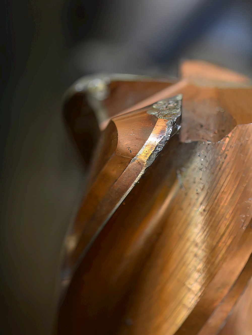
Built-up edges look like shiny material parts on the top or flank of the cutting edge. They lead to small pits or craters on the rake face of the tool and ultimately to cutting edge chipping. Built-up edges typically occur in gummy materials such as non-ferrous materials, super-alloys and stainless steels and during operations involving slower cutting speeds and feeds.
Do you want to know more about how to control tool wear for best production efficiency? Participate in our course on Tool deterioration or ask for a GTDA onsite project in your workshop. Contact your local Seco representative for more information.
Overview of basic Tool Wear Patterns in Machining This is an overview of the most observed singular tool wear patterns on cutting tools. These include:Flank and crater wearBuilt-up edgesChippingThermal crackingPlastic deformationNotch wearChip hammeringEdge breakageFor each of these tool wear patterns, we provide some of the possible counter measures to avoid or at least minimize their impact on the machining process. Flank Wear analysisFlank wear is the most desirable tool wear condition. It is rather predictable and dependable, while offering a well-defined relation between flank wear and achievable tool life. However, flank wear that occurs too rapidly – resembling classic flank wear but develops in a very short time period – can be a problem.When does flank wear occur?At lower cutting speeds, the main cause of flank wear is abrasion and erosion. Hard microscopic inclusions of carbides or strain hardened workpiece material particles cut into the cutting tool. Small pieces of coating then break off and cut into the tool face. The cobalt eventually wears out of the matrix. This reduces the adhesion of the carbide grains, causing them to break away as well.At higher cutting speeds, diffusion wear is the main cause of flank wear because higher cutting speeds generate higher temperatures on the cutting edge. Thus creating favorable conditions for diffusion to take place.Flank wear resembles a relatively uniform abrasion along the tool’s cutting edge. Occasionally, metal from the workpiece smears over the cutting edge and can exaggerate the apparent size of the wear scar.Flank wear appears when machining all types of workpiece materials, and a cutting edge will normally fail due to flank wear if it doesn’t fail by other types of wear first.Corrective actions to minimize Flank WearSome corrective actions to minimize flank wear are:reducing the cutting speed (in some cases increase the feed can help also)select a more wear resistant, harder carbide gradeapply coolant correctly Crater Wear analysisCrater wear is a combination of diffusion and decomposition (higher cutting speeds) and abrasive wear (lower cutting speeds). The heat from the workpiece chips decomposes the tungsten carbide grains in the substrate and carbon leeches into the chips (diffusion). This results in wearing a ‘crater ‘on the rake face of the insert. The crater will eventually grow large enough to cause the insert flank to chip or may cause rapid flank wear.Crater wear takes the shape/appearance of a crater or pits on the rake face of inserts. Crater wear is visible mostly when machining abrasive workpiece materials like e.g., cast irons or workpieces with a hard surface like e.g., forged workpieces.Corrective actions to minimize Crater WearTo minimize crater wear, it is best to:use coatings containing thick layers of e.g., aluminium oxideapply coolantuse a free cutting geometry that reduces heat andto lower cutting speeds and feeds Built-up Edges analysisBuilt-up edges (BUE) are caused by adhesion of workpiece material that is pressure welded to the cutting edge. This occurs when there is chemical affinity, high pressure and sufficient temperature in the cutting zone.Eventually, the built-up edge breaks off and takes pieces of the cutting edge with it, leading to chipping and rapid flank wear.When does it occur?Built-up edges look like shiny material parts on the top or flank of the cutting edge. They lead to small pits or craters on the rake face of the tool and ultimately to cutting edge chipping. Built-up edges typically occur in gummy materials such as non-ferrous materials, super-alloys and stainless steels and during operations involving slower cutting speeds and feeds.Corrective actions to prevent Built-up EdgesTo prevent built-up edge wear,increase the cutting speed and or feed rateselect an insert with a sharper geometry and a smoother rake facecorrectly apply coolant at an increased concentration Chipping Wear analysisChipping is caused by mechanical instability or cracks in the cutting material. Chipping of the cutting edge is often a result of vibrations in the workpiece or machine tool or the tool itself. Hard inclusions in the surface of the workpiece material and interrupted cuts result in concentrations of localized stress that can cause cracks and chipping. Chipping looks like small bits broken out of the cutting edge and is common in non-rigid situations. Workpiece materials with hard particles (e.g. precipitation hardening workpiece materials) will also cause cutting edge chipping.Corrective actions to minimize Chipping WearCorrective actions include:proper machine tool setupminimizing deflectionusing a tougher carbide grade and stronger cutting edge geometryreducing the feed (especially at the entrance or exit of the cut) and increasing the cutting speed. (See also corrective actions for built-up edge.) Thermal Cracks analysisThermal cracks are caused by a combination ofthermal loads (high temperature in the cutting zone)thermal variations or gradients (changing temperatures in the cutting edge)Stress cracks develop roughly perpendicular to the cutting edge, eventually causing sections of carbide to pull out and the edge to chip. Thermal cracks can be observed mostly in milling and interrupted cut turning. Intermittent coolant flow can also lead to thermal cracks.Corrective actions to minimize Thermal CracksSome corrective actions areapply coolant correctlyselect a tougher carbide gradereduce the cutting speed and the feeduse a free cutting geometry that reduces heatconsider a different machining method (ratio time in cut/time out of cut) Plastic Deformation analysisThermal overloading is the main cause of plastic deformation. Excessive heat causes the carbide binder (cobalt) to soften. Then due to mechanical overloading, pressure on the cutting edge makes it deform or sag at its tip, eventually breaking off or leading to rapid flank wear.Plastic deformation looks like a deformed cutting edge. Careful observation is needed because plastic deformation can look very similar to flank wear on a cutting edge.When does it occur?Expect plastic deformation when cutting temperatures are high (high cutting speeds and feeds) and when the workpiece material is high strength in nature (hard steels or strain hardened surfaces and superalloys).Corrective actions to prevent Plastic DeformationSome corrective actions are:applying coolant properlyreducing cutting speeds and feedsusing an insert with a larger nose radius opting for a harder, more wear resistant carbide grade Notch Wear analysisNotch wear happens when the surface of a workpiece is harder or more abrasive than its underlying material. This can be due to surface hardening during previous cuts (strain hardening materials like stainless steels and super-alloys) or originate from forged or cast surfaces with a surface scale. All of which causes the cutting edge to wear more rapidly at the point where the cutting edge contacts the hard layer. This localized concentrated stress can also lead to notch wear. What happens? Compressive stress develops along the cutting edge that’s in contact with workpiece material, while it doesn’t occur where the cutting edge is not in contact. This causes high stress on the cutting edge at the point where the two are in direct contact (depth of cut line). Impact of any sort, such as hard micro inclusions in the workpiece material or slight interruptions can also cause notch wear.Corrective actions to prevent Notch WearSome corrective actions includereducing feed rate and varying the depth of cut when using multiple passesincreasing cutting speeds if machining a high temp alloy (this will give more flank wear)selecting a tougher carbide gradeusing a chip breaking geometry for high feeds needed to prevent built-up edges, especially in stainless and heat resistant alloys Chip Hammering analysisChip hammering is a phenomenon caused by chip curling back and hitting the unused part of a cutting edge. Breakage of a cutting edge (or part of a cutting edge) that is not in cut will be the result. The risk that this happens is greater with operations involving high feeds and deep depths of cut combinations.Corrective actions to prevent Chip HammeringTo correct for chip hammeringchange the feed rate and the cutting depthselect a different cutting edge angleuse a different chip breaking geometry go with a tougher carbide grade Cutting Edge BreakageAny overview of basic tool wear patterns must also include cutting edge breakage, although breakage itself is not considered a wear pattern. Catastrophic breakage of the cutting edge is not a tool wear pattern, but an unwanted and dangerous phenomenon caused by using tools incorrectly. When a cutting edge breaks, it means that the selection of the cutting conditions was such that the mechanical loads acting on the cutting edge are so great that the they cannot withstand them. Corrective actions to prevent edge breakageStart with lower values for the cutting conditions (mainly depth of cut and feed) or choose a stronger cutting edge (tougher carbide grade or stronger geometry). It could also be that one of the previous mentioned wear patterns expanded and weakened the cutting edge so much that it could no longer withstand the loads acting upon it. In these instances, changing to a new cutting edge earlier will prevent breakage. Indications on Tool WearWear descriptions concentrate on the visual aspect of tool wear. In addition to that, there are other phenomena that can be observed when the cutting edge is wearing. These can indicate that the tool is wearing out and is perhaps ready to be replaced.Sudden breakage of the cutting tool. This is a very unpleasant way of signalling that the cutting tool is due for replacement. There are so many elements influencing how a cutting edge deteriorates that it is not always feasible to take all into account, and that can lead to breakage of a cutting edge in some cases. If tool breakage happens in a systematic way, the operation needs to be stopped and fully evaluated. Systematic tool breakage indicates that there is an unbalance between the loads acting on the cutting edge and the load bearing capacity of the tool. Cutting forces should be lowered or a stronger cutting edge should be selected.The fingernail test is one of the simplest tests to evaluate the status of the cutting edge. The presence of built-up edges or micro chipping of the cutting edge may not be visible by the naked eye, but they can definitely be felt with a fingernail. Built-up edge and chipping should be minimized during the operation.Changes in the noise level during machining can indicate that a tool is wearing out. Sharp, high frequency noises indicate poor cutting conditions.Chips that change form, shape or color during machining are yet another indication that the shape of the cutting edge is changing, e.g. due to tool wear progressing.When the surface roughness of a machined surface degrades, that could also signal that it is time to change the cutting edge (reaching end of tool life).Increasing power consumption or vibration tendency. Do you need help identifying tool wear?Tool deterioration is the process by which the condition of a cutting tool becomes increasingly worse and gradually causes the tool to lose its ability to perform in line with expectations. Tool deterioration comes as aging-wear, sudden impact phenomena like breakage and as chemical interactions between workpiece material and cutting material.Aging-wear is a process of progressive surface damage leading to removal of material from one or both of two solid surfaces in solid state contact, occurring when these two solid surfaces are in sliding or rolling motion contact in environmental conditions of pressure and temperature.This overview of basic singular tool wear patterns gives basic remedies to take care of tool wear that is for the machinist unacceptable in form or in pace of development.Do you want to know more about how to control tool wear for best production efficiency? Participate in our course on Tool deterioration or ask for a GTDA onsite project in your workshop. Contact your local Seco representative for more information. Contact Us Inline Content - SurveyCurrent code - 5fce8e61489f3034e74adc64
So it's a reamer speed and feeds, milling speeds and feeds, and drill feeds and speeds calculator (plus more) all rolled into one.
Are you planning a general home renovation? Go ahead and check our stair calculator and the decking calculator – they may come in handy!
Notch wear happens when the surface of a workpiece is harder or more abrasive than its underlying material. This can be due to surface hardening during previous cuts (strain hardening materials like stainless steels and super-alloys) or originate from forged or cast surfaces with a surface scale. All of which causes the cutting edge to wear more rapidly at the point where the cutting edge contacts the hard layer. This localized concentrated stress can also lead to notch wear. What happens? Compressive stress develops along the cutting edge that’s in contact with workpiece material, while it doesn’t occur where the cutting edge is not in contact. This causes high stress on the cutting edge at the point where the two are in direct contact (depth of cut line). Impact of any sort, such as hard micro inclusions in the workpiece material or slight interruptions can also cause notch wear.
Crater wear is a combination of diffusion and decomposition (higher cutting speeds) and abrasive wear (lower cutting speeds). The heat from the workpiece chips decomposes the tungsten carbide grains in the substrate and carbon leeches into the chips (diffusion). This results in wearing a ‘crater ‘on the rake face of the insert. The crater will eventually grow large enough to cause the insert flank to chip or may cause rapid flank wear.
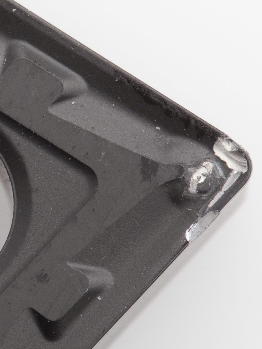
Chipping is caused by mechanical instability or cracks in the cutting material. Chipping of the cutting edge is often a result of vibrations in the workpiece or machine tool or the tool itself. Hard inclusions in the surface of the workpiece material and interrupted cuts result in concentrations of localized stress that can cause cracks and chipping.
Flank wear resembles a relatively uniform abrasion along the tool’s cutting edge. Occasionally, metal from the workpiece smears over the cutting edge and can exaggerate the apparent size of the wear scar.
If you are not sure how many teeth your tool has, look at it end-on and count how many sharp cutting edges there are around the circumference of the tool.
Thermal overloading is the main cause of plastic deformation. Excessive heat causes the carbide binder (cobalt) to soften. Then due to mechanical overloading, pressure on the cutting edge makes it deform or sag at its tip, eventually breaking off or leading to rapid flank wear.Plastic deformation looks like a deformed cutting edge. Careful observation is needed because plastic deformation can look very similar to flank wear on a cutting edge.
Crater wear takes the shape/appearance of a crater or pits on the rake face of inserts. Crater wear is visible mostly when machining abrasive workpiece materials like e.g., cast irons or workpieces with a hard surface like e.g., forged workpieces.
Chip hammering is a phenomenon caused by chip curling back and hitting the unused part of a cutting edge. Breakage of a cutting edge (or part of a cutting edge) that is not in cut will be the result. The risk that this happens is greater with operations involving high feeds and deep depths of cut combinations.
Let's go through an example of how to calculate speeds and feeds manually, using the speeds and feeds formulas discussed above. Your tool is half an inch in diameter and made of high-speed steel, and you are end-milling a block of aluminum. Looking up the average surface speed between the cutting tool and the aluminum, you find it to be 600 feet/min. Using the imperial speeds formula, you would perform the calculation:
Physicist at the Institute of Nuclear Physics in Kraków interested in magnetism and always ready to explain everything to everyone in simple terms. He is currently working on adding more scientific papers to his collection, accompanied by his son and another baby on its way. A perfectionist with an acute eye for detail, he has a unit converter in his brain and uses it to compare prices at the supermarket. Loves peace and quiet, especially during hiking. See full profile
In manual mode, you can set the cutting speed (usually in surface feet per minute – sfm), and it will output the rotation speed in rotations per minute (rpm), therefore converting sfm to rpm. You can also set custom chip loads to calculate the feed rates. Let's look at each mode in detail next.
You will then see results for the range of speeds you should use. For the best outcome, start at the minimum speed and gradually increase it to the average figure. If you want a quick, but rough finish, carry on up to the maximum speed.
Continue reading to learn about machine tool operations and the two principal speeds and feeds formulas that power this calculator.
Next, enter the number of teeth the tool has to get the range of feed rates to use. The feed rates shown are for the average rotation speed. To calculate the feed rates at a different speed, enter the RPM into the custom rotation speed field. Similar to rotation speed, the slower the feed rate, the smoother the finish of the operation will be.
Next, let's calculate the average feed rate at 4584 RPM4584\ \mathrm{RPM}4584 RPM, given that your tool has two teeth, and it has an average chip load when milling aluminum, which is 0.0040.0040.004 inches:
Expect plastic deformation when cutting temperatures are high (high cutting speeds and feeds) and when the workpiece material is high strength in nature (hard steels or strain hardened surfaces and superalloys).
At higher cutting speeds, diffusion wear is the main cause of flank wear because higher cutting speeds generate higher temperatures on the cutting edge. Thus creating favorable conditions for diffusion to take place.

Ideally, you would also calculate the minimum and maximum speeds and feeds, so let's see how our calculator can work out everything for you in super-quick time.
If you are using the metric system and have the surface speed VVV in meters per second and the diameter DDD in millimeters, the equation is:
The "speeds" part of the speeds and feeds calculator is the rotation speed of either the tool (e.g., for drilling) or the workpiece (e.g., for turning on a lathe). For a given tool and workpiece material, there is a range of recommended cutting or surface speeds between the two materials. Given the surface speed, you can calculate the spindle speed in revolutions per minute (RPM) using the following equation (when using imperial units):
Stress cracks develop roughly perpendicular to the cutting edge, eventually causing sections of carbide to pull out and the edge to chip. Thermal cracks can be observed mostly in milling and interrupted cut turning. Intermittent coolant flow can also lead to thermal cracks.
In preset mode, you can select the operation, tool material, size and number of teeth, and the workpiece material. The calculator contains a range of recommended cutting speeds for different materials, allowing it to calculate the rotation speeds. It also has the corresponding chip load data to calculate the feed rates.
The term "feeds" refers to the feed rate or the relative linear speed between the tool and the workpiece. For example, for drilling, it is the speed at which the drill bit travels down into the workpiece material. The equation for the feed rate is:
For each of these tool wear patterns, we provide some of the possible counter measures to avoid or at least minimize their impact on the machining process.
Tool deterioration is the process by which the condition of a cutting tool becomes increasingly worse and gradually causes the tool to lose its ability to perform in line with expectations. Tool deterioration comes as aging-wear, sudden impact phenomena like breakage and as chemical interactions between workpiece material and cutting material.
Aging-wear is a process of progressive surface damage leading to removal of material from one or both of two solid surfaces in solid state contact, occurring when these two solid surfaces are in sliding or rolling motion contact in environmental conditions of pressure and temperature.
The chip load depends on the characteristics of the tool and the workpiece material. For example, a tool drilling a hole into a soft workpiece material will have a higher chip load than a harder workpiece material.
Analyzing the equation, you might notice that π×D\pi \times Dπ×D is the formula for circumference of a circle. So we're dividing the speed at the circumference by the distance traveled during one rotation to get the number of rotations per minute.
Wear descriptions concentrate on the visual aspect of tool wear. In addition to that, there are other phenomena that can be observed when the cutting edge is wearing. These can indicate that the tool is wearing out and is perhaps ready to be replaced.
This overview of basic singular tool wear patterns gives basic remedies to take care of tool wear that is for the machinist unacceptable in form or in pace of development.
Built-up edges (BUE) are caused by adhesion of workpiece material that is pressure welded to the cutting edge. This occurs when there is chemical affinity, high pressure and sufficient temperature in the cutting zone.
Chipping looks like small bits broken out of the cutting edge and is common in non-rigid situations. Workpiece materials with hard particles (e.g. precipitation hardening workpiece materials) will also cause cutting edge chipping.
Start with lower values for the cutting conditions (mainly depth of cut and feed) or choose a stronger cutting edge (tougher carbide grade or stronger geometry). It could also be that one of the previous mentioned wear patterns expanded and weakened the cutting edge so much that it could no longer withstand the loads acting upon it. In these instances, changing to a new cutting edge earlier will prevent breakage.
Finally, it supports the turning operation where the cutting tool is stationary, and the workpiece rotates. This configuration is the essential operation of a lathe machine, which is used to create symmetric circular manufactured items.


 0086-813-8127573