
ER16 1" Straight Shank Collet Chuck, TSC - er16 collet dimensions
At present, Wodenco has a thousand different types of carbide inserts. You can name your product needs, we will surely satisfy your needs.
Please note that the process described in this post is a smaller outline of a more detailed process described on my whitepaper. For a more rigorous study of making a tolerance analysis and the tolerance stack, check out my whitepaper.
For now, the focus of this exercise is the top line of this section: Arithmetic Stack (Worst Case). The value in the tolerance column represents the sum of all the tolerances in the stack. It looks like we will currently not be able to meet the requirements because our total possible misalignment is ± 0.486 mm but our requirements state that we need to be within ± 0.25 mm. We now need to make some fixes to the architecture which we will do in the next step, Adjust.
Usedcarbide inserts suppliers
The detailed design phase usually has multiple, iterative sub-phases as the design progresses and representative prototypes are built. Phases 2B and 2C are typically the largest efforts in the product development process, where the specific implementation for all disciplines occurs (mechanical, industrial design, electrical, firmware, systems, software, manufacturing, and quality).
The design team works closely with the manufacturing team to enable a smooth transfer, often with Simplexity engineers traveling to the contract manufacturer sites to ensure product quality. The design is transferred to the client based upon specific needs, most often after all tests are complete and the design is verified.
In a case like this, you would need to do a tolerance analysis of the tolerance stack-up to make sure the design will work. A tolerance analysis looks at all the relevant tolerances in a system and adds them so that we can improve the design to meet a certain design requirement. A tolerance stack-up analysis is usually done on a spreadsheet. Feel free to use this template to get started. We will be using this template later in this article to walk through the analysis.
Because tolerance analyses are often done before detailed design is complete, I highly recommend making a rough block diagram of your system. Basic diagrams clarify important interfaces and dimensions before the design is detailed, and they serve as an important tool for communicating your findings at design reviews.
H-level accuracy. Large rake angle and relief angle make the cutting edge of the insert sharper, and the cutting is more brisk while ensuring effective chip breaking of the insert.
M-level double-sided chip breaker groove has excellent chip breaker performance when processing P-class mild steel and medium carbon steel, and can obtain high-quality finished surface.
Our carbide inserts allow fast machining, dimensional stability, and better surface finish on metal parts. Wodenco inserts also have low-temperature resistance, good thermal and electrical conductivity, and many other excellent properties. Wodenco is the name you can trust for world-class carbide inserts.
Together with a strong technical workforce and well-equipped testing equipment, Wodenco provides cutting-edge tools for you.
Neil Foxman is a Senior Systems Engineer at Simplexity’s San Diego office. In 2014, he graduated with a Bachelor of Science in Mechanical Engineering from Tufts University and has since taken Electrical Engineering master’s degree courses at University of California, San Diego. Since joining Simplexity in 2015, Neil has worked on a variety of mechanical, electrical, and software designs.
Ultra metcarbidegrades
M-level double-sided chip breaker groove, with wiper design, can obtain better surface quality in high-feed and efficient.
Careers at Simplexity Employment Verification Join our Mailing List! Privacy Policy Simplexity Product Development Copyright © 2024 | All Rights Reserved
G-level precision, sharp edge, small tip arc, effectively prevent vibration during machining, suitable for precision boring and precision machining of outer circle.
M-level double-sided chip breaker groove, the first choice for light load rough machining, metal removal rate and cutting edge economy can be obtained.

We proudly claim that our WODENCO CNC carbide inserts match or even surpass world-renowned brands in quality and performance. We are constantly innovating and improving to ensure our blades stay on top.
M-level double-sided, high cutting edge strength, is the solution to overcome the undesirable processing factors such as sand hole and slag inclusion in the cast iron processing.
High-quality material: We have carefully selected world-class carbide materials to ensure the insert’s excellent wear resistance, high strength and excellent cutting performance. Whatever the material, our inserts handle it with ease, ensuring precise and efficient cutting operations.
Now that you have a better sense of the parts used in the stack, you can start finding each part’s manufacturing tolerances. In the Architecture Phase the goal is to get a rough-order-of-magnitude or “ROM” estimation of each part’s tolerances to catch if your design is way off and needs larger architectural or manufacturing changes.
High-quality carbide inserts that exceed industry standards. Contain excellent properties such as wear and tear resistance. Compete with world famous brands.
Even if the production methods allow you to design tight tolerances on a single part, you need to consider the tolerances of all the parts around it to make sure that the overall system functions correctly.
Let’s look at an example design: a microscope fixture. The bottom surface of our microscope needs to be held at a specific height above a slide (6 ± 0.25 mm), so we plan to design a microscope stand, a slide holder, and a mounting plate for the parts to be mounted on. We plan to machine all the parts using a CNC milling machine which has an accuracy of ± 0.2 mm. The machining tolerance zone is smaller than the required tolerance zone, so no problem, right?
The rest of the tolerances are machining tolerances between features on the microscope holder, slide holder, and slide. We can enter that information into the spreadsheet as shown. Notice how each dimension is fully described in order from the microscope to the slide.
The E-level double-sided chip breaker groove has the advantages of high transposition accuracy, hard working prevention, strong wear resistance, and can obtain high machining accuracy and high quality finished surface.
First, we will focus on technique 4: introducing compliance into the system. This concept introduces more complexity to your design, but it is likely to significantly reduce the total tolerance stack of your system. Instead of fixing each part at a single position and making the machining tolerances tight for all the parts, consider allowing most of the parts to have loose tolerances or move in space. Then introduce an engagement step or clamping step where the critical parts are aligned with a single part.
Next, we can assume that the microscope stand and slide holder are made using a CNC milling machine, so we would like to find some tolerances for these parts. Looking at our manufacturer website, they claim that their usual machining tolerance is 0.005” (0.13 mm).
Through that, the inserts offer high impact resistance, heat and oxidation resistance, wear and tear resistance, corrosion resistance, and oxidation resistance. It can resist corrosion by the acid, atmosphere, alkali, and other elements. It does not also oxidize easily.
Well, actually no. Each of the machined parts may be 0.2 mm away from what we want. So, if the microscope stand is 0.2 mm taller after machining, and if the slide holder comes out 0.2 mm thinner, then the slide would actually be 0.4 mm away from the nominal 6.0 mm, causing the image to be out of focus.
Finally, the slide thickness will have its own tolerance. If we are early in the design process, we can do a Google search for glass slide manufacturers and take a rough guess at the slide thickness tolerance assuming we will revisit it later. In this case let’s assume we contacted our slide manufacturer, and the manufacturer quotes their thickness tolerance zone to be within 0.13 mm.
Wodenco will give you the best top-quality cutting tools products based on your specific requirements with our technical R&D personnel. Wodenco will 100% supports your carbide inserts on whole development.
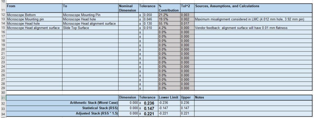
We first enter the tolerance from the microscope bottom to the microscope mounting pin. Enter the description of the relevant features in the From and To columns and the numerical tolerance on the top line. Ignore the nominal dimension column for this study, and don’t change the formulas in the gray columns because these will update automatically. The second section in your tolerance stack should now look like this:
Moreover, we can produce various cutting tools products as per special requirements. Wodenco welcomes both, OEM and ODM customers. We have technical R&D personnel to help you, including 15 senior experts.
This blog will continue examining the example mentioned earlier: A microscope fixture. A rough sketch of the parts envisioned for this design are shown below.
We are now within our target tolerance zone! This architecture should work for our design, but it’s worth noting that the complexity has increased: you now have to design the spring mechanism and investigate if the additional forces on the slide cause it to break or warp.
So far, we have been using the Arithmetic Stack (Worst Case) row to determine if the design is feasible. In the list of possible design adjustment techniques above, we may also consider technique 6 for our example which analyzes the stack using the Statistical Stack (RSS) or Adjusted Stack (RSS * 1.5). These calculations use the Statistical perspective of the tolerance stack: it is unlikely that all the parts will be at their absolute worst case condition at the same time, so statistical methods (RSS) can be used to better quantify a more realistic and smaller tolerance zone. The RSS stack multiplied by a factor of 1.5 is sometimes preferred as a more conservative estimate.
The M-level double-sided chip breaker groove has the advantages of small cutting force and wide chip breaker range, which can also get better chip breaking effect on alloy steel with high viscosity.
It’s a good idea to be verbose with what dimension you are referring to in the From and To columns so that your thinking can be more clearly communicated to a reviewer and to give yourself a reminder during design.
Carbideinsert identification chart PDF
We will plan to mount the microscope on the microscope stand using some alignment features. Assume our microscope has a datasheet that claims the tolerance between the bottom of the microscope and a mounting pin is 0.05 mm.
In our microscope holder example, this could be a custom designed Microscope Head that is spring loaded against the top surface of the slide. In this case we don’t care as much about the tolerances of the other parts, and only need to control the dimension between the Microscope mount features and the slide surface. Our system and tolerance stack would then look like:
The M-level double-sided chip breaker groove has the advantages of high transposition accuracy, high work hardening prevention and wear resistance, and higher work efficiency than NF.
If you’re looking for carbide inserts for your project or business needs, Wodenco is your best choice to manufacture your carbide inserts orders. Wodenco is one of the leading carbide inserts manufacturer and all cutting tools solution that meet and exceed international standards. We provide product at more competitive price based on exact project.
Wodenco carbide inserts contain properties that will be suitable for a wide variety of standard applications. If you are a reliable supplier in China for inserts, then Wodenco will be your perfect place.
As a professional manufacturer, Wodenco offer the best cutting tools solution throughout a diverse product portfolio. Wodenco is dedicated to providing full services, from research and development, production, marketing to exporting. With more than 10 years of experience, Wodenco had established a perfect management system.
Advanced manufacturing process: We use the most advanced CNC manufacturing technology in the production process to ensure the consistency and stability of each insert. Our experienced team of engineers can precisely design and manufacture the perfect blade to meet your specific needs.
Finally, make sure the tolerances mentioned on the tolerance stack match the tolerances used on the mechanical drawings. Once your drawings and tolerance analysis spreadsheet are aligned, your tolerance analysis is completed, and you are ready for release!
M, G-level precision, high cutting edge strength, suitable for inner hole and outer circle machining of cast iron materials.
G-level precision, large front angle, surface polishing treatment, effectively prevent built-up edge, can obtain high quality finished surface and long life.
M-level single-sided chip breaker groove, strong edge, high safety, strong plastic deformation resistance under high metal removal rate.
G-level, PCBN and PCD superhard materials are welded to the cemented carbide matrix, which are the solutions for processing materials with high hardness and non-ferrous metals
The M-level single/double-sided chip breaker groove has strong impact resistance. The groove design has the best balance point in the edge safety and sharpness, solves the difficulties such as high cutting heat and sticking phenomenon in the processing of stainless steel, and achieves high efficiency.

We are an ISO9001 certified company with more than 20,000,000 pieces of annual output. Wodenco is more than capable to produce top-quality cutting tools products, especially carbide inserts. You can purchase products at very reasonable prices.
Simplexity has a dedicated New Product Introduction (NPI) team that can guide the transition from design into production. The NPI team presents multiple options for manufacturing to the client, allowing clients to choose the solution that best suits their needs. This can involve Simplexity performing initial builds in-house prior to full handoff to a contract manufacturer or building the product via established relationships with contract manufacturing partners either domestically or overseas early in the process.
Carbide inserts suppliersnear me
Although the microscope fixture uses generally simple part geometries, it’s worth noting that you should try to visualize how each part will be made, as some production methods can have vastly different tolerances depending on the part orientation. For instance, sheet metal tolerances between two edges on the same plane can have much tighter tolerances than the dimension between an edge and a bend as shown below. 3D printed parts may also be sensitive to the build orientation. In general, machined parts have tighter tolerances when the part is only held in one orientation, but tolerances increase between features when the part is flipped or moved within the machine. For all these manufacturing methods, smaller dimensions may also have tighter tolerances than larger dimensions.
Phase 2C iterates on the learnings of Phase 2B and involves a refined prototype build of a fully integrated system. Some projects also benefit from additional iterations of the product based on prior learnings through additional phases (2D, 2E, etc), which are not represented in this graphic. All requirements are intended to be tested, and at the end of Phase 2 there will be confidence that the units will pass verification in Phase 3. The Bill of Materials is further refined, and the team updates estimates for the per unit cost of the product by receiving pricing from vendors and suppliers.
Bestcarbide inserts suppliers
Tolerance analyses don’t just apply to mechanical parts; in the engineering world, most measurements are approximate and knowing the tolerances of the components you buy can help you better gauge the performance of the overall system. For example, most electronic components have tolerances associated with their values, or operate within a range of acceptable supply voltages or currents.
G-level precision, large rake angle design, sharp cutting edge, faster cutting, it is the preferred groove for precision turning of small shaft parts.
Simplexity typically engages with production component suppliers and contract manufacturing groups early in this phase to provide additional manufacturing input on the design. If the product has stringent testing or certification requirements, pre-screens are performed in this phase prior to formal regulatory agency testing.
Broad applicability: Our inserts are suitable for a wide variety of CNC cutting equipment and applications. Whether you’re in metalworking, machining, mold making or aerospace, our inserts provide you with cutting excellence.
M-level double-sided breaker groove, sharp edge, effectively solve the processing difficulties of stainless steel chip breaking, sticking phenomenon, surface hardening, etc., and obtain high-quality finished surface.
M-level double-sided chip breaker groove, with higher edge strength than DM, is suitable for semi-finishing with unstable working conditions, and can also be used for cast iron processing to obtain lower cutting force.
G-level precision, PCBN, PCD superhard materials are welded to the cemented carbide matrix, which is the solution of high hardness and non-ferrous metal processing.
Wholesalecarbide inserts suppliers
Besides, carbide inserts, we have been central to the design and production of carbide turning inserts, special inserts, CNC insert, Vertical milling cutting inserts, Indexable milling inserts, and non-standard special-shaped products.
Being a reliable and professional manufacturer of carbide inserts, Wodenco aims to provide high satisfaction service to customers around the world. We had achieved a consistent reputation in the market and strive to maintain it for the next long years to come.
G-level double-sided, ceramic blade, blade angle can be used to process hardened steel, cast iron, steel and other materials under different treatment conditions.
Carbide insertschart
The M-level single-sided chip breaker groove has high cutting edge safety, and can obtain high metal removal rate and low cutting force under large cutting depth and greater feeding.
Sometimes the tolerances are just too tight to design around, and you need to start looking at more expensive operations. Some additional options are listed below.
Carbide insert from Wodenco is able to bring product manufacturing molds and measuring tools live up to twenty to fifty times longer than that of alloy steel. Aside from that, there’s no need for the molded product to be reprocessed or to go through re-grinding.
Each time a tolerance analysis is conducted it can generally be split into three steps: Prepare, Stack, and Adjust (or PSA). The whole tolerance analysis should be conducted twice. First, you want to take an early look in the Architecture Phase to determine if the general design planned is feasible from a tolerance perspective. Secondly, you will want to revisit your design in the Detail Design Phase before release to make sure you can confidently purchase parts without worrying about tolerance stack issues.
Transforming your mechanical CAD designs into real and tangible parts is one of the most rewarding feelings as an engineer. However, a lot of things can go wrong during this transition. One of the most common and most overlooked problems are tolerances. Have you ever tried mounting your TV on your wall, but the holes don’t line up perfectly? Or do you have to jiggle your keys every time you open the front door? These issues occur because of poorly controlled tolerances.
Now that we have an idea of the relevant part tolerances, it’s time to create our Tolerance Stack using the template provided. Let’s enter each tolerance found earlier into the spreadsheet. It helps if there is a logical order to the tolerances entered in the spreadsheet, so we will look at each dimension along the way from the bottom of the microscope to the top of the slide.
The M-level double-sided chip breaker groove can effectively solve the processing difficulties of stainless steel chip breaking and sticking phenomenon, and obtain higher processing efficiency than EF.
We are proud to introduce a new generation of CNC carbide inserts, bringing unprecedented breakthroughs to your cutting process. As an innovative enterprise of CNC inserts, we know that in modern manufacturing, the quality of inserts directly affects product quality, production efficiency and cost control. Therefore, we constantly strive for excellence and strive to provide you with high-quality inserts that compete with world-renowned brands.
The detailed design phase starts with defining options for the product architecture, with the goal of having the greatest chance of successfully meeting product requirements while best mitigating risk. Engineering activities in this phase include presenting options for hardware components, outlining the system block, sequence, and state diagrams, creating rough CAD, and breadboarding of high-risk subsystems. Results are presented with a description of the pros, cons, and key tradeoffs for each scenario.
Wodenco has a set of standards of carbide inserts and cutting tools in the tooling, milling, and other industries. With part quality, high-tech equipment, and quality test system, and excellent customer service, customers rely on us, both local and international customers.
Wodenco is the leading manufacturer of carbide inserts in China. We offer a broad selection of carbide inserts, a range of styles, and sizes to suit your application demand. Whether need for your business or a project, Wodenco is your best choice for carbide inserts.
For tight tolerance applications, you will commonly find yourself adjusting the tolerance stack or the mechanical architecture to meet the requirements. If the designed tolerances are too loose, you can try some of the following techniques.
Let’s plan to fit the mounting pin on the microscope into a clearance hole on the microscope stand. Looking again at the microscope datasheet, we see that the mounting pin has a diameter of 3.95 ± 0.03 mm. A common ISO 286 tolerance zone for a hole is H7 which has an asymmetric 0.012 mm tolerance zone (4.000 +0.012, -0.000 mm). For other hole/shaft fits, you can use the tool on Engineer’s Edge. This tolerance zone is asymmetric, but we will revisit this fit in the stack phase to see how it can be used.
E, G-level precision, sharp edge, suitable for finishing of inner hole and outer circle of high temperature alloy materials.
To capture this possible misalignment in our tolerance stack, we need to add another line showing this position tolerance possibly including some notes on how this tolerance was achieved.
Categories: Engineering & Analysis, Product Development & Design, Mechanical Engineering, Prototyping & Manufacturing, Simplification
If you need to make architecture or manufacturing changes, repeat the process: Prepare and research what the updates entail, add or remove parts in the Stack, and Adjust the design until the tolerances are reasonable and you can proceed with more detailed design.
I would recommend looking for tolerances on rapid prototyping manufacturer websites. Most prototyping manufacturers automate their process, so they are more likely to post tolerance information online. For instance, we commonly use Protolabs for machining prototype parts, and they have good design guides with tolerances for CNC milled parts, CNC turned parts, and sheet metal parts.
M-level precision, suitable for rough machining of inner hole and outer circle of steel, stainless steel, cast iron and other materials.
Wodenco carbide inserts are made of tungsten carbide. A kind of alloy material used to machine resulting in optimum strength and rigidity.
Send us your special project requirements, we will give you the best cutting tool product solution based on your detailed requirement.
Carbide inserts suppliersusa
In the Detail Design Phase, you will want some more confidence in the tolerances you are researching which may entail contacting specific suppliers and comparing different supplier tolerances. For injection molded parts and cast metal parts, a vendor may provide you with a Design for Manufacturability (DFM) document that highlights issues with your design. Even if the manufacturer had previously quoted certain tolerances, the tolerances may be adjusted (for better or worse) after a rigorous DFM that looks at thin features or possible warping during manufacturing.
Next, some care needs to be taken when considering the fitment between the microscope mounting pin and the hole in the microscope holder. Because this is a clearance hole, there can be some misalignment, and we need to consider the worst-case condition for our tolerance stack. In this case, we get a maximum misalignment of the microscope to the microscope holder in the Least Material Condition where the hole is at 4.012 mm and the pin is at 3.92 mm. This means that there is a possible misalignment of 0.046 mm as shown below.
Long Life and Stability: Our CNC carbide inserts have excellent durability and stability. Whether cutting at high speeds or operating under heavy loads, our inserts maintain consistent performance, reducing downtime and increasing productivity.
Although every project is different, if you remember to Plan, Stack, and Adjust during each of your tolerance analyses, you can quantify the total tolerance of your system, and more confidently release your mechanical designs for production.


 0086-813-8127573