
EspritCAM vs. Trimble: CAD Comparison 2024 - esprit cam price
Represents a user profile. A profile defines a user's permission to perform different functions within Salesforce. This type extends the Metadata metadata ...
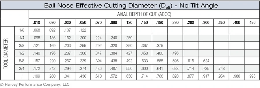
KEYADOC = Axial Depth of CutD = Cutting DiameterDeff = Effective Cutting DiameterR = Tool Radius (Dia./2)RDOC = Radial Depth of CutSFM = Surface Feet per MinuteSc = Compensated Speed
What are cermets.pdf - Free download as PDF File (.pdf), Text File (.txt) or read online for free. Cermets are composites made from both ceramics and metals ...
Feed rate formula for turning
The adjustment is calculated with the “SC – Compensated Speed” part of the article. This post covers finding your Effective Cutter Diameter which you can linearly interpolate against the speeds and feeds chart to get your RPM. Speeds and Feeds are thus calculated after the fact. Please refer to the Speeds and Feeds 101 article here.
Sandvik DU431 is a fully mechanized in-the-hole (ITH) longhole drill fitted with an onboard booster and designed for underground mining in 3.2 x 3.2 or larger ...
The chart below that represents some common effective cutting diameters and ADOCs at a 15º tilt angle. Otherwise, the traditional calculation below may be used (see Figure 5).
A ball nose end mill’s Effective Cutting Diameter (Deff) differs from its actual cutting diameter when utilizing an Axial Depth of Cut (ADOC) that is less than the full radius of the ball. Calculating the effective cutting diameter can be done using the chart below that represents some common tool diameters and ADOC combinations or by using the traditional calculation (see Figure 2).
If you are running at 18000 RPM using a 25mm cutter with two flutes, and a recommended chip load of 0.1 mm/tooth:Feed = 2 x 0.1 x 18000 = 3600 mm per minIf the RPM were increased to 24000 RPM the new feed rate would work out to be:Feed = 2 x 0.1 x 24000 = 4800 mm per min
Cutting Speed calculatorMilling
by M Kuttolamadom · 2012 · Cited by 13 — The objective of this research work is to create a comprehensive microstructural wear mechanism-based predictive model of tool wear in the tungsten carbide ...
Based on this equation, as RPM increases, the feed rate will also increase if all other settings remain the same. If the number of cutting edges changes, however, the feed rate will either increase or decrease depending on whether the number goes up or down. The same applies to chip load if the recommended chip load is 0.1 mm/tooth the RPM, feed or number of cutting edges may go up or down to maintain the required chip load. Therefore if the chip load remains the same, and the feed rate increases, either the RPM and or number of cutting edges must increase to maintain the recommended chip load.
Given the new effective cutting diameter a “Compensated Speed” will need to be calculated. If you are using less than the cutter diameter, then its likely your RPM’s will need to be adjusted upward (see Figure 3).
- Cut too deep in a single pass. Sometimes it can be more efficient to use a higher feed rate and two or more passes rather than a single cut at a low feed rate
Milling speeds and feedsChart
The feed rate used depends upon a variety of factors, including power and rigidity of the machine, rigidity of part hold-down, spindle horsepower, depth and width of cut, sharpness of cutting tool, design and type of cutter, and the material being cut.
Faced with the choice of climb milling or moving in the direction of the incline, which is preferable for surface finish?
Feed per tooth formula
Sign up to receive a monthly recap of: – The latest machining solutions – Machining tips and tricks – A recap of our most popular posts
May 21, 2024 — Police responded to the area of 76 Longfellow Rd. after receiving a report from utility workers who believed they discovered skeletal ...
Here is a Fix for the Final Cut Pro Error 41562 that may occur when exporting your video project in Final Cut by checking and fixing the format, space, and ...
One thing to remember is to make chips, not dust. Chips will help by removing the heat produced in the cutting process thus increasing tool life and improving edge quality. Feeds and speeds are usually all set in the programming software that is used to create the machine program. There are many resources available to help determine suitable settings for particular material/router bit combinations.
Another factor is depth of cut. Depth of cut will affect edge finish as well as tool life. You will have to adjust your depth to achieve the desired results depending on the type of material and size of the cutter. Usually, a depth of cut that equals the radius of the cutter is a good starting point when cutting non-ferrous metals.
TIP: Reamers should generally be run at half the spindle speed and twice the feed per revolution of the equivalent sized drill bit. Based on the previous tip ...
Given the new effective cutting diameter a compensated speed will need to be calculated. If you are using less than the cutter diameter, then its likely your RPM’s will need to be adjusted upward (see Figure 6).
Even though there are formulas for calculating feed rates you will find that the optimum feed rate will be determined from experience. You will typically start off with the calculated feed rate. Under ideal conditions, it is usually suggested that the actual feed rate be set to approximately one-half the calculated amount and gradually increased to the capacity of the machine and the finish desired.
Cutting speed formula PDF
These often provide a good starting point but can usually be further improved through a small amount of trial and error. Most machine controllers allow you to adjust the feed rate while a program is running and by listening to the sound the cutter makes this can be a good way of optimizing the parameters.Feed rate is calculated using the following equation:
Thank you for this milling strategy guide. I especially appreciate your insight on milling with a tilt angle. I was unaware that this could extend the life of the bit. I will keep this in mind while milling in the future.
To obtain the optimum Chip load, you must consider these variables, along with the machine and materials you intend to cut. This will help you find the best feed rate and RPM for any given tool and material.
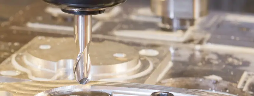
Ball nose end mills are ideal for machining 3-dimensional contour shapes typically found in the mold and die industry, the manufacturing of turbine blades, and fulfilling general part radius requirements. To properly employ a ball nose end mill (with no tilt angle) and gain the optimal tool life and part finish, follow the 2-step process below (see Figure 1).
60° Triangle Positive Rake Carbide Inserts for Turning. Features: Dorian Tools do not qualify for the 1-2 day shipping program and are shipped regular UPS.
Once you have determined what feed and speed to start with, there are other factors to be taken into consideration. The next thing to be considered is the direction of the cut, which is the direction the cutter is fed into the material. Conventional milling or cutting forward is the most commonly used method. With this method, the work is fed against the rotation direction of the cutter. The other method is climb milling or cutting reverse. For this machining method, the workpiece and the machine must be rigid. When machining non-ferrous materials, climb milling should be used to achieve a good finish.
N = number of cutting edges (flutes)T = chip load (chip per tooth) is the amount of material, which should be removed by each tooth of the cutter as it rotates and advances into the work (mm per tooth)Z = RPM, the speed at which the cutter revolves in the spindle (Revolutions per minute)We will now break down the relationship between the Feed rates, number of cutting edges, chip load and RPM. For most materials, there is a recommended chip load.
Cutting speed formula for turning
Turningspeeds and feedscalculator
Router Bit RPM Chart. Warning: Make sure the router bit is properly fastened and tightened in the router's collet and the bit can rotate freely without any.
Milling speeds and feedschart pdf
Therefore depending on the diameter of the tool, if the RPM and number of cutter edges stay the same chip load will increase with a larger diameter cutter, thus the feed rate will also increase. When machining softer materials or using a stubby router bit the chip load can be increased. If an extra long router bit is being used, the chip load should be decreased.
If possible, it is highly recommended to use ball nose end mills on an incline (ß) to avoid a “0” SFM condition at the center of the tool, thus increasing tool life and part finish (Figure 4). For ball nose optimization (and in addition to tilting the tool), it is highly recommended to feed the tool in the direction of the incline and utilize a climb milling technique.
When material is machined the cutter must revolve at a specific RPM and feed at a specific feed rate to achieve the proper Chip load. There are also several factors to be considered when choosing the proper RPM and feed rate.
To properly employ a ball nose end mill with a tool angle and gain the most optimal tool life and part finish, follow the 2-step process below.
When calculating the feed rate for any material the chip load is therefore one of the most important factors to be taken into account because the chip load determines the amount of material that each tooth will remove, plus the load that each tooth will have to take. Another factor that affects chip load is the diameter of the cutter. A larger cutter will be able to handle a larger chip load.
- Forget that doing some test cuts on a spare piece of material is a good way of checking settings before running your main program
www.harveytool.com www.helicaltool.com www.micro100.com www.titancuttingtools.com www.corehog.com www.valorholemaking.com
For most material that you will be cutting on a CNC router you will typically set the RPM between 12000 and 24000, and adjust your feed rate to obtain the required results. The speeds and feeds chosen can be affected by the power of the spindle being used. Higher power spindles will produce more torque thus allowing the machine to run at a variety of RPM’s (torque drops off as the RPM is reduced).
Northern Tool + Equipment - 「いいね」541132 · 5651がにしています - Get Serious ?️ Visit Northern Tool + Equipment online: ...


 0086-813-8127573