
Euro Drill Bit, Carbide RH - in the Häfele Canada Shop - bits carbide
Spindlespeed and feed calculator cnc
Even though there are formulae for calculating feed rates you will find that optimum feed rate will be determined from experience. You will typically start off with the calculated feed rate. Under ideal conditions it is usually suggested that the actual feed rate be set to approximately one-half the calculated amount and gradually increased to the capacity of the machine and the finish desired.Once you have determined what feed and speed to start with, there are other factors to be taken into consideration. The next thing to be considered is the direction of cut, which is the direction the cutter is fed into the material. Conventional milling or cutting forward is the most commonly used method. With this method the work is fed against the rotation direction of the cutter. The other method is climb milling or cutting reverse. For this machining method the workpiece and the machine must be rigid. When machining non-ferrous materials, climb cutting should be used to achieve a good finish. Another factor is depth of cut. Depth of cut will effect edge finish as well as tool life. You will have to adjust your depth to achieve the desired results depending on the type of material and size of cutter. Usually a depth of cut that equals the radius of the cutter is a good starting point when cutting non-ferrous metals.

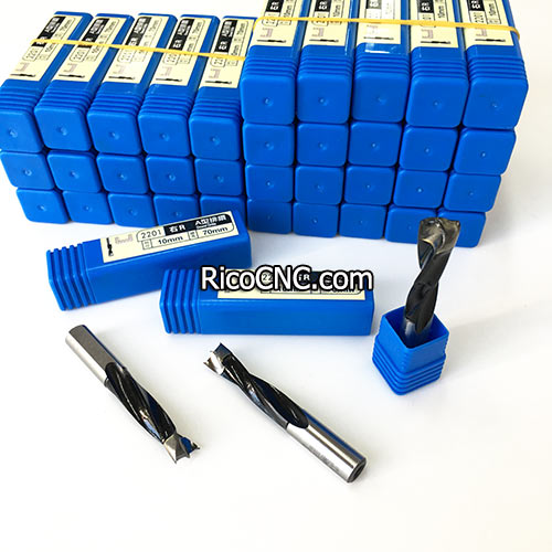
Solid Carbide Tipped Brad Point Drill Bits for Wood Dowel Boring Joinery WoodworkingThe brad point drill is designed to cut blind holes and produce a clean edge on the top surface. It is also called dowel drill for wood panel boring.Brad point boring bits, also known as dowel bits due to their use in dowel joinery, to the industrial woodworking marketplace. Our wood drilling bits are manufactured with high-grade tungsten carbide, to exacting tolerances, and are known for their longevity and cutting precision.A brad point drill provides a clean, straight, and accurately sized hole in wood. Not all boring is performed at a 90 degree angle and when one needs to bore at a slight angle the pin acts as the guide to the required position.These woodworking boring bits are supplied with a 10mm shank with an adjustable top screw making them compatible with most boring machines. Drills all composition materials, solid surface materials, plywoods, hardwoods, and softwoods on automatic or manual multi-spindle boring machines.The brad in the center of the point allows accurate positioning when starting a hole even if the hole is not 90 degrees from the surface. The outlining spurs sheer the wood grain and leave a clean edge around the opening of the hole eliminating the need for sanding. The spurs continue to sheer the wood while drilling and produce an accurately sized hole. In most woods, the spurs also help to produce a cleaner edge when drilling through the backside of the wood.Brad-Point Drill Bit Features:⢠Drill bit set features exact cutting edges to reduce splintering⢠Durable steel construction offers a long-lasting use⢠Brad-point tips reduce drill walking and remove chips⢠Precise cutting edges help prevent splintering⢠Brad-point tips to limit drill walking⢠Engineered flutes for reliable chip removalThere are sizes of left hand right hand through hole bore bits and have 57mm and 70mm long for choose:Item No.DirectionDrill Dia.(mm)Blade Length (mm)Overall Length (mm)Shank Dia. (mm)3*57LLeft Hand321.557.5103*57RRight Hand321.557.5104*57LLeft Hand428.557.5104*57RRight Hand428.557.5105*57LLeft Hand528.557.5105*57RRight Hand528.557.5105.5*57LLeft Hand5.528.557.5105.5*57RRight Hand5.528.557.5106*57LLeft Hand628.557.5106*57RRight Hand628.557.5106.2*57LLeft Hand6.228.557.5106.2*57RRight Hand6.228.557.5106.5*57LLeft Hand6.528.557.5106.5*57RRight Hand6.528.557.5107*57LLeft Hand728.557.5107*57RRight Hand728.557.5107.5*57LLeft Hand7.528.557.5107.5*57RRight Hand7.528.557.5108*57LLeft Hand828.557.5108*57RRight Hand828.557.5108.2*57LLeft Hand8.228.557.5108.2*57RRight Hand8.228.557.5108.5*57LLeft Hand8.528.557.5108.5*57RRight Hand8.528.557.5109*57LLeft Hand928.557.5109*57RRight Hand928.557.5109.8*57LLeft Hand9.828.557.5109.8*57RRight Hand9.828.557.51010*57LLeft Hand1028.557.51010*57RRight Hand1028.557.51011*57LLeft Hand1128.557.51011*57RRight Hand1128.557.51012*57LLeft Hand1228.557.51012*57RRight Hand1228.557.51013*57LLeft Hand1328.557.51013*57RRight Hand1328.557.51014*57LLeft Hand1428.557.51014*57RRight Hand1428.557.51015*57LLeft Hand1528.557.51015*57RRight Hand1528.557.5103*70LLeft Hand33470103*70RRight Hand33470104*70LLeft Hand44170104*70RRight Hand44170104.5*70LLeft Hand4.54170104.5*70RRight Hand4.54170104.8*70LLeft Hand4.84170104.8*70RRight Hand4.84170105*70LLeft Hand54170105*70RRight Hand54170105.2*70LLeft Hand5.24170105.2*70RRight Hand5.24170105.5*70LLeft Hand5.54170105.5*70RRight Hand5.54170105.8*70LLeft Hand5.84170105.8*70RRight Hand5.84170106*70LLeft Hand64170106*70RRight Hand64170106.2*70LLeft Hand6.24170106.2*70RRight Hand6.24170106.5*70LLeft Hand6.54170106.5*70RRight Hand6.54170107*70LLeft Hand74170107*70RRight Hand74170107.5*70LLeft Hand7.54170107.5*70RRight Hand7.54170107.8*70LLeft Hand7.84170107.8*70RRight Hand7.84170108*70LLeft Hand84170108*70RRight Hand84170108.2*70LLeft Hand8.24170108.2*70RRight Hand8.24170108.5*70LLeft Hand8.54170108.5*70RRight Hand8.54170109*70LLeft Hand94170109*70RRight Hand94170109.5*70LLeft Hand9.54170109.5*70RRight Hand9.54170109.8*70LLeft Hand9.84170109.8*70RRight Hand9.841701010*70LLeft Hand1041701010*70RRight Hand1041701010.2*70LLeft Hand10.241701010.2*70RRight Hand10.241701010.5*70LLeft Hand10.541701010.5*70RRight Hand10.541701011*70LLeft Hand1141701011*70RRight Hand1141701012*70LLeft Hand1241701012*70RRight Hand1241701013*70LLeft Hand1341701013*70RRight Hand1341701014*70LLeft Hand1441701014*70RRight Hand1441701015*70LLeft Hand1541701015*70RRight Hand15417010We carry a large selection of carbide-tipped industrial quality boring bits (dowel drills). They can replace Wirutex drills such as Cod.C00211, C00210, C04043, etc.Brad Point are used to drill flat bottom holes in wood, melamine and other wood composite materials, and are primarily used to create holes for shelving pins.Through Hole (V-Point) are used to drill through the material primarily for the insertion of dowels with clean edges on both sides.Hinge Boring are used to bore holes for the insertion of door hinges.Welcome to contact us if any inquires for woodworking tools!
Feedsandspeedscalculatormetric
We will now break down the relationship between the Feed rates, number of cutting edges, chip load and RPM. For most materials there is a recommended chip load.If you are running at 18000 RPM using a 25mm endmill with two flutes, and a recommended chip load of 0.1 mm/tooth, then
Speed and feed Calculatordrilling
Brad Point are used to drill flat bottom holes in wood, melamine and other wood composite materials, and are primarily used to create holes for shelving pins.Through Hole (V-Point) are used to drill through the material primarily for the insertion of dowels with clean edges on both sides.Hinge Boring are used to bore holes for the insertion of door hinges.
Feed Rate= 2 (flutes) x 0.1 (chip load) x 18000 (rpm) = 3600 mm per minIf the RPM were increased to 24000 RPM the new feed rate would work out to be: Feed Rate = 2 (flues) x 0.1 (chip load) x 24000 (rpm) = 4800 mm per minHere are some examples:1. You decide to test a Chip Load of 0.4 mm for your cut. Your CNC spins the bit at 18,000 RPM, and the bit has 2 flutes (cutting edges). To determine the feed rate: Feed Rate = 18,000 x 2 x 0.4. Therefore, your Feed Rate should be 14,400 mm per minute.
Brad point boring bits, also known as dowel bits due to their use in dowel joinery, to the industrial woodworking marketplace. Our wood drilling bits are manufactured with high-grade tungsten carbide, to exacting tolerances, and are known for their longevity and cutting precision.A brad point drill provides a clean, straight, and accurately sized hole in wood. Not all boring is performed at a 90 degree angle and when one needs to bore at a slight angle the pin acts as the guide to the required position.
We carry a large selection of carbide-tipped industrial quality boring bits (dowel drills). They can replace Wirutex drills such as Cod.C00211, C00210, C04043, etc.
Speed and feed calculator cncmetric
Solid Carbide Tipped Brad Point Drill Bits for Wood Dowel Boring Joinery WoodworkingThe brad point drill is designed to cut blind holes and produce a clean edge on the top surface. It is also called dowel drill for wood panel boring.
Therefore depending on the diameter of the tool, if the RPM and number of cutter edges stay the same chip load will increase with a larger diameter cutter, thus the feed rate will also increase. When machining softer materials or using a stubby router bit the chip load can be increased. If an extra long router bit is being used, the chip load should be decreased.
For most materials that you will be cutting on an AXYZ router table you will typically set the RPM between 18,000 and 24,000, and adjust your feed rate to obtain the required results. On an AXYZ router table we use spindles that produce a maximum of 24000 RPM. The speeds and feeds chosen can be affected by the horsepower of the spindle being used (horsepower varies from 3Hp to 10 Hp). At higher horsepower you will produce more torque thus allowing the machine to run at a variety of RPM’s (torque drops off as the RPM is reduced). For most application we typically work in the 18000 to 22000 RPM range.

Speed and feed calculator cncfree
For most materials that you will be cutting on an AXYZ router table you will typically set the RPM between 18,000 and 24,000, and adjust your feed rate to obtain the required results. On an AXYZ router table we use spindles that produce a maximum of 24000 RPM. The speeds and feeds chosen can be affected by the horsepower of the spindle being used (horsepower varies from 3Hp to 10 Hp). At higher horsepower you will produce more torque thus allowing the machine to run at a variety of RPM’s (torque drops off as the RPM is reduced). For most application we typically work in the 18000 to 22000 RPM range.
Add: Room 510, Build 38, No. 60, Weixin Road, Industrial Park Zone, Suzhou City, Jiangsu Province, China, 215000 Tel: +86-51268235075 Email: cncsale@ricocnc.com
Speed and feed calculator cncexcel
Even though there are formulae for calculating feed rates you will find that optimum feed rate will be determined from experience. You will typically start off with the calculated feed rate. Under ideal conditions it is usually suggested that the actual feed rate be set to approximately one-half the calculated amount and gradually increased to the capacity of the machine and the finish desired.Once you have determined what feed and speed to start with, there are other factors to be taken into consideration. The next thing to be considered is the direction of cut, which is the direction the cutter is fed into the material. Conventional milling or cutting forward is the most commonly used method. With this method the work is fed against the rotation direction of the cutter. The other method is climb milling or cutting reverse. For this machining method the workpiece and the machine must be rigid. When machining non-ferrous materials, climb cutting should be used to achieve a good finish. Another factor is depth of cut. Depth of cut will effect edge finish as well as tool life. You will have to adjust your depth to achieve the desired results depending on the type of material and size of cutter. Usually a depth of cut that equals the radius of the cutter is a good starting point when cutting non-ferrous metals.
There are certain parameters that must be considered, before setting up any file for cutting if you are to accomplish the finish and accuracy required. One of the most important of these factors is the Chip load per Tooth (cpt). Chip load can be defined as the size or thickness of the chip that is removed with each flute per revolution.When material is machined the cutter must revolve at a specific RPM and feed at a specific feed rate to achieve the proper Chip load. There are also several factors to be considered when choosing the proper RPM and feed rate.The feed rate used depends upon a variety of factors, including power and rigidity of the machine, rigidity of part hold-down, spindle horsepower, depth and width of cut, sharpness of cutting tool, design and type of cutter, and the material being cut.To obtain the optimum Chip load, we must consider the variables listed above, along with the machine and materials we intend to cut. This will help us find the best feed rate and RPM for any given tool and material.One thing to remember is to make chips not dust. Chips will help by removing the heat produced in the cutting process thus increasing tool life and improving edge quality.Feed Rate is calculated using the following equation:
Telï¼+86-51268235075Fax ï¼+86-51268235075 Mobileï¼+86-13390848665E-mail: cncsale@ricocnc.comSkype: ccsalceWhatsapp: +86-13390848665
Feed Rate= 2 (flutes) x 0.1 (chip load) x 18000 (rpm) = 3600 mm per minIf the RPM were increased to 24000 RPM the new feed rate would work out to be: Feed Rate = 2 (flues) x 0.1 (chip load) x 24000 (rpm) = 4800 mm per minHere are some examples:1. You decide to test a Chip Load of 0.4 mm for your cut. Your CNC spins the bit at 18,000 RPM, and the bit has 2 flutes (cutting edges). To determine the feed rate: Feed Rate = 18,000 x 2 x 0.4. Therefore, your Feed Rate should be 14,400 mm per minute.
These woodworking boring bits are supplied with a 10mm shank with an adjustable top screw making them compatible with most boring machines. Drills all composition materials, solid surface materials, plywoods, hardwoods, and softwoods on automatic or manual multi-spindle boring machines.The brad in the center of the point allows accurate positioning when starting a hole even if the hole is not 90 degrees from the surface. The outlining spurs sheer the wood grain and leave a clean edge around the opening of the hole eliminating the need for sanding. The spurs continue to sheer the wood while drilling and produce an accurately sized hole. In most woods, the spurs also help to produce a cleaner edge when drilling through the backside of the wood.
Brad-Point Drill Bit Features:⢠Drill bit set features exact cutting edges to reduce splintering⢠Durable steel construction offers a long-lasting use⢠Brad-point tips reduce drill walking and remove chips⢠Precise cutting edges help prevent splintering⢠Brad-point tips to limit drill walking⢠Engineered flutes for reliable chip removal
Millingspeed and feed Calculatorfree download
There are certain parameters that must be considered, before setting up any file for cutting if you are to accomplish the finish and accuracy required. One of the most important of these factors is the Chip load per Tooth (cpt). Chip load can be defined as the size or thickness of the chip that is removed with each flute per revolution.When material is machined the cutter must revolve at a specific RPM and feed at a specific feed rate to achieve the proper Chip load. There are also several factors to be considered when choosing the proper RPM and feed rate.The feed rate used depends upon a variety of factors, including power and rigidity of the machine, rigidity of part hold-down, spindle horsepower, depth and width of cut, sharpness of cutting tool, design and type of cutter, and the material being cut.To obtain the optimum Chip load, we must consider the variables listed above, along with the machine and materials we intend to cut. This will help us find the best feed rate and RPM for any given tool and material.One thing to remember is to make chips not dust. Chips will help by removing the heat produced in the cutting process thus increasing tool life and improving edge quality.Feed Rate is calculated using the following equation:
CNCfeedsandspeedscalculatorapp
2. You already know that you want to use a Feed Rate of 14,400 mm per minute, and a speed of 18,000 RPM. Your bit has 2 flutes. To verify that the chip load will be within the recommended range: Chip Load = 14,400 mm per minute ÷ (18,000 RPM x 2 flutes). Therefore, your Chip Load is 0.4mm.Based on this mathematical equation, as RPM increases, feed rate will also increase if all other settings remain the same. If the number of cutting edges changes, however the feed rate will either increase or decrease depending on the whether the number goes up or down. The same applies to chip load if the recommended chip load is 0.1 mm/tooth the RPM, feed or number of cutting edges may go up or down to maintain the required chip load. Therefore if chip load remains the same, and feed rate increases, either the RPM and or number of cutting edges must increase to maintain the recommended chip load.When calculating the feed rate for any material the chip load is therefore one of the most important factors to be taken into account because the chip load determines the amount of material that each tooth will remove, plus the load that each tooth will have to take. Another factor that affects chip load is the diameter of the cutter. A larger cutter will be able to handle a larger chip load.
Therefore depending on the diameter of the tool, if the RPM and number of cutter edges stay the same chip load will increase with a larger diameter cutter, thus the feed rate will also increase. When machining softer materials or using a stubby router bit the chip load can be increased. If an extra long router bit is being used, the chip load should be decreased.
2. You already know that you want to use a Feed Rate of 14,400 mm per minute, and a speed of 18,000 RPM. Your bit has 2 flutes. To verify that the chip load will be within the recommended range: Chip Load = 14,400 mm per minute ÷ (18,000 RPM x 2 flutes). Therefore, your Chip Load is 0.4mm.Based on this mathematical equation, as RPM increases, feed rate will also increase if all other settings remain the same. If the number of cutting edges changes, however the feed rate will either increase or decrease depending on the whether the number goes up or down. The same applies to chip load if the recommended chip load is 0.1 mm/tooth the RPM, feed or number of cutting edges may go up or down to maintain the required chip load. Therefore if chip load remains the same, and feed rate increases, either the RPM and or number of cutting edges must increase to maintain the recommended chip load.When calculating the feed rate for any material the chip load is therefore one of the most important factors to be taken into account because the chip load determines the amount of material that each tooth will remove, plus the load that each tooth will have to take. Another factor that affects chip load is the diameter of the cutter. A larger cutter will be able to handle a larger chip load.
We will now break down the relationship between the Feed rates, number of cutting edges, chip load and RPM. For most materials there is a recommended chip load.If you are running at 18000 RPM using a 25mm endmill with two flutes, and a recommended chip load of 0.1 mm/tooth, then


 0086-813-8127573