
Ferrite, Austenite, Martensite and Solid Solutions - austenite vs martensite
Discontinuous chips are produced in brittle workpiece materials under conditions that include large chip thicknesses, low cutting speeds and small rake angles. On machine tools with low stability, short chips can lead to micro vibrations during the operation because of intermittent chip formation. These types of chips offer one advantage: convenient handling and disposal. Formation of these chips in brittle materials produces fairly good surface finish, consumes less power and yields reasonable tool life. With ductile materials, however, discontinuous chips produce poor surface finishes and excessive tool wear.
A built-up edge forms when small particles of workpiece material stick to the cutting edge. This occurs mainly with soft and ductile workpiece materials and when continuous chips form. A built-up edge may affect the cutting action of a tool. This built-up material is extremely hard and brittle, and becomes unstable as successive layers add to it. When a built-up edge breaks off, part of it is carried up the face of the tool along with the chip while the remainder is left in the machined surface. This latter part roughens the machined surface.
The quality of the tool is most important. This guide highlights the types of routers and router bits. It contains router basics information.
A chip breaking diagram such as Figure 16 provides a graphical representation that relates different types of chip breaking geometries and their applications to each other. This diagram ranks different chip breaking geometries (named FF1, FF2, MF1 … RR97) relative to their cutting-edge strength and application. The horizontal axis represents the relative cutting edge strength of the geometry. To some extent, it also indicates the feeds suitable for certain geometries.
Read on for specifics on using a router to smooth edges or cut grooves in the wood. These are two common uses for a table router or handheld router.
Figure 15 illustrates the influence of cutting speed on chip formation. The horizontal axis of the graph shows the feed and the vertical axis represents types of chips. In general, as feeds increase, chips tend to become shorter, especially at low cutting speeds. As cutting speed increases, however, the relationship between feed and chip formation chip becomes lower.
When you’re routing a board, you do all four sides. The end of a board often splinters when you rout it. The culprit is the transition from routing end grain to routing side grain. One of the challenges of learning how to use a table router is getting a smooth and un-splintered edge.
A geometry positioned at the lower left of this diagram is very sharp and generates short chips, but it also offers low cutting-edge strength that requires equally low cutting conditions (depths of cut and feeds). Conversely, geometries at the top right of the diagram have strong cutting edges and can be used with high cutting conditions, but they tend to form long chips.
When you’re doing other finishing work and know how to use a trim router, it’s important to go slowly. Splintered laminate won’t give the same finished look. By carefully guiding your router along the edge, you can get a smooth finish on your work.
Woodworkers achieve a lot of mileage with routers. You may have questions like “What is a woodworking router? What are routers used for?” A wood router is a great tool for making cutouts, duplicating patterns, sharp edges, cut joints, decorative surface cuts, and more.
If you decide between the two types of wood router, the plunge router has an advantage when starting a cut in the middle of a board. Place the router over the starting point, turn it on, and slide the rotary drill bit into the wood.
How to influence chip formation Good chip formation produces spiral-shaped chips and guarantees good tool life, easy chip handling and evacuation, good surface quality and a stable, reliable, efficient cutting process. In short, a good chip must be an easy-to-handle size and require minimal effort to generate. ToolCutting conditionsMaterialCoolantRake angleCutting Edge angleNose radius Coating Cutting edge and chipbreakergeometryFeed Cutting depth Chip thickness ratio Cutting speedHardness Tensile strength Ductility StructureDry machining Emulsion cooling Seco Jetstream Various groups of factors offer practical ways to influence chip formation, including cutting tools, cutting conditions, materials and cooling system.Material factors include workpiece hardness and tensile strength, ductility and structural considerations. These elements cannot be modified to improve chip formation, but the machinist must consider their impact on chip formation.The influence of cooling system on chip formation is rather arbitrary. It is very difficult to see fixed relationships between the type of cooling system and its impact on chip formation. One exception is the so-called HPDC (High Pressurized Directed Cooling) system, which clearly leads to much-shorter chips. This type of cooling system is applied in the Seco Jetstream tooling system.The impact of tool features on chip formation is a frequent topic of discussion. Of main importance here are the rake angle and cutting-edge angle, nose radius, and the geometry of the cutting edge and chip breaker. Larger rake angles, lower cutting-edge angles and a larger nose radius yield longer chips. The impact of the coating type on chip formation is not clearly definable.The most practical way to influence chip formation is to modify cutting conditions, which can be very easy and effective to change. The basic cutting condition to adjust is chip thickness ratio or slenderness. When chip thickness ratio is too small, it produces so-called square chips that create overly high loads on the tool nose and thus limit tool life considerably. A too-high chip thickness ratio leads to slender ribbon-shaped chips that are very difficult to break into short pieces.Chip thickness ratio is defined as the width of cut divided by the thickness of the chip. The depth of cut for a given feed should be large enough to avoid a too-small or too-large chip thickness ratio. Small depths of cut combined with certain feeds produce square chips. Overly small feeds can lead to ribbon-shaped chips that are unbreakable.In practice, depth of cut often is a given. In this situation, the feed forms the key to good chip formation. Avoid both overly low feeds that lead to long ribbon-shaped chips and overly high feeds that create square chips.The more-complex influence of cutting speed on chip formation will be discussed in greater detail later in this chapter. General description of basic chip types Actual cross section defines four different types of chips:Serrated, segmented or noncontinuous chipsContinuous chips with narrow, straight, primary shear zones, or continuous chips with a secondary shear zone at the toolchip interfaceBuiltup edge chipsShearing chips or short chipsAll chips have two surfaces. The outer surface displays a shiny, polished surface because it rubs – and causes wear – on the rake face of the tool. Every chip also has an inner surface formed by the original surface of the workpiece, with a jagged, rough appearance caused by the actual shearing mechanism. Segmented chipContinous chipChip withbuilt-up edgeShearing chip Serrated or segmented chips – also called non-continuous chips – are semi-continuous chips with large zones of low shear strain and small zones of high shear strain or shear localization. These types of chips appear when machining materials with low thermal conductivity and high strain-hardening tendencies. The material strength increases when the stress in the material increases, especially in combination with a higher temperature, as is the case with titanium. These chips display a saw-tooth appearance.Continuous chips form when machining ductile materials, including mild steel, copper and aluminum. The plastic deformation of ductile material produces long, continuous chips, desirable from the perspective of cutting action because it produces good surface roughness with low power consumption and longer tool life. Continuous chips often form with a small chip thickness, high cutting speed, sharp cutting edge, large rake angle on the cutting tool, smooth tool face and an efficient lubricating system. These chips are difficult to handle and evacuate. They can coil in a very long spiral or helix shape that curls around the workpiece and tool and may injure the operator when the chip breaks. The tool face is in contact for a longer period, which produces more frictional heat. Chip breakers can rectify this problem.Deformation takes place along a narrow shear zone called the primary shear zone. Some continuous chips may develop a secondary shear zone at the tool/chip interface. This zone becomes thicker as friction increases. Continuous chips also may occur with a wide primary shear zone that displays curved boundaries. The lower boundary of the deformation zone – the side flow effect – can drop below the machined surface, which distorts the surface and leads to a poor surface finish.A built-up edge forms when small particles of workpiece material stick to the cutting edge. This occurs mainly with soft and ductile workpiece materials and when continuous chips form. A built-up edge may affect the cutting action of a tool. This built-up material is extremely hard and brittle, and becomes unstable as successive layers add to it. When a built-up edge breaks off, part of it is carried up the face of the tool along with the chip while the remainder is left in the machined surface. This latter part roughens the machined surface.Increased cutting speeds and rake angle, sharper tools, use of coolant and of a cutting material with lower chemical affinity for the workpiece material can reduce the formation of built-up edge. Figure 9: Examples of built-up edges and chips for different cutting speeds. Shearing chips or short chips – also called discontinuous chips – consist of segments that are detached from each other. These chips form when cutting brittle workpiece materials such as bronze, hard brass and gray cast iron, as well as very hard materials or those with hard inclusions and impurities. Brittle materials lack the ductility necessary for appreciable plastic chip deformation. Repeated fracturing limits the amount of chip deformation.Discontinuous chips are produced in brittle workpiece materials under conditions that include large chip thicknesses, low cutting speeds and small rake angles. On machine tools with low stability, short chips can lead to micro vibrations during the operation because of intermittent chip formation. These types of chips offer one advantage: convenient handling and disposal. Formation of these chips in brittle materials produces fairly good surface finish, consumes less power and yields reasonable tool life. With ductile materials, however, discontinuous chips produce poor surface finishes and excessive tool wear. A. Carbon steel with continuous chipB. Duplex stainless steel with segmented chipC. Carbon steel with a built-up edgeD. Cast iron with discontinuous chips Chip breaking geometries Long and continuous chips tend to have a negative effect on machining efficiency, with a risk of damage to the cutting tool, workpiece and machine tool. They can lead to unnecessary production stoppages because of chip-evacuation problems and create unsafe work conditions for the operator. These chips should be broken into small pieces for safety, easy removal and prevention of damage to the machine tool and workpiece.Chips develop a curvature or curl during formation based on factors that include the following:distribution of stresses in the primary and secondary shear zonesthermal effectsstrain-hardening characteristics of the workpiece materialcutting tool geometryto some extent, the cooling systemIn general terms, when the rake angle decreases (negative tooling), chip curvature becomes tighter, which leads to shorter, broken chips. Chip breakers serve to reduce the radius of chip curvature and thus break chips into shorter lengths. A. ChipB. Without chip breakerC. With chip breakerD. Chip breakerE. ToolF. Workpiece Select chip-breaking geometries based on the type of operation, the combination of feed and depth of cut, and the type of workpiece material. A. CornerB. Cutting edge A chip-breaking diagram (see Figure 14) can show the relationship among workpiece material, cutting conditions, chip-breaking geometry and chip formation. This diagram identifies the considerations involved in selecting depth of cut and feed to machine a specific workpiece material with a defined chip-breaking geometry. The horizontal axis represents the feed, which always must be larger than a certain minimum (the width of the T-land geometry) and should remain lower than a certain maximum (never larger than half the nose radius). The vertical axis shows the depth of cut, which always should be larger than the nose radius to promote good chip formation and avoid problems with square chips. Additionally, the depth of cut never should be larger than the cutting edge length. In the latter case, it is advisable to work with safety factors, which depend on the strength of the cutting edge. In the case of inserts, these safety factors vary between 75% (for square or rhombic inserts) and 20% (for copy inserts with a small top angle) of the cutting edge length. Together, both depth of cut and feed – the so-called chip thickness ratio – must remain between certain constraints. The maximum chip thickness ratio should remain below a certain maximum value to avoid too-long ribbon-shaped chips. The chip thickness ratio also should remain above a minimum value to avoid square chips. Figure 14 represents these constraints with two angled lines. The minimum and maximum value of the chip thickness ratio depends on workpiece material. To minimize broken cutting edges, the cutting forces should not rise too high. Figure 14 shows this constraint as a curved line.Every combination of feed and depth of cut in the blue zone in Figure 14 will produce correctly shaped chips. In a combination selected outside this blue zone, the cutting edge and chip breaking geometry will not function well. Chips will be too long or too square, or the cutting-edge breakage will exceed an acceptable amount. Figure 15 illustrates the influence of cutting speed on chip formation. The horizontal axis of the graph shows the feed and the vertical axis represents types of chips. In general, as feeds increase, chips tend to become shorter, especially at low cutting speeds. As cutting speed increases, however, the relationship between feed and chip formation chip becomes lower. ISO material group use, negative basic shape inserts Stainless steel (ISO M)Superalloys (ISO S) Steel (ISO P)Stainless steel (ISO M)Superalloys (ISO S) Stainless steel (ISO M) Steel (ISO P)Stainless steel (ISO M)Hardened steel (ISO H) Superalloys (ISO S) Steel (ISO P)Stainless steel (ISO M)Cast iron (ISO K) Steel (ISO P)Cast iron (ISO K) Cast iron (ISO K) Steel (ISO P) A chip breaking diagram such as Figure 16 provides a graphical representation that relates different types of chip breaking geometries and their applications to each other. This diagram ranks different chip breaking geometries (named FF1, FF2, MF1 … RR97) relative to their cutting-edge strength and application. The horizontal axis represents the relative cutting edge strength of the geometry. To some extent, it also indicates the feeds suitable for certain geometries.The vertical axis represents the type of application, ranging from finishing (small depths of cut) to roughing (large depths of cut). To some extent, the vertical axis represents relative depths of cut suitable for certain geometries. The actual size of the insert – the cutting-edge length – also influences the effective depth of cut. The various ISO-defined colors indicate which workpiece materials suit these geometries.A geometry positioned at the lower left of this diagram is very sharp and generates short chips, but it also offers low cutting-edge strength that requires equally low cutting conditions (depths of cut and feeds). Conversely, geometries at the top right of the diagram have strong cutting edges and can be used with high cutting conditions, but they tend to form long chips. 5 steps for trouble-free chip formation in a sustainable machining processPrioritize the process-optimization criterion: either productivity or cost efficiency.If chip formation is acceptable, go to step 5.If chips are too long, go to step 3.If chips are too short, go to step 4.If productivity is important, increase the feed.If cost efficiency is important, change the chip breaker to a stronger geometry.Keep the feed within the range of the chip-breaking geometry.Go to step 5.If productivity is important, change the chip breaker to a sharper geometry.If cost efficiency is important, reduce the feed.Keep the feed within the range of the chip-breaking geometry.Go to step 5.If cost efficiency is a priority, lower cutting speeds to improve it.If productivity is a priority, increase cutting speeds to improve it. Inline Content - SurveyCurrent code - 5fce8e61489f3034e74adc64
Learn how to use a router guide to get straight lines with unpiloted bits. Straight bits, also called unpiloted bits, have no guide bearings on the end. They’ll only cut in a straight line when you guide the router against a fence. Always use a router guide, or fence, when using unpiloted bits.
Good chip formation produces spiral-shaped chips and guarantees good tool life, easy chip handling and evacuation, good surface quality and a stable, reliable, efficient cutting process. In short, a good chip must be an easy-to-handle size and require minimal effort to generate.
Safety Tip: Recklessly running wood through the router could injure you, the project or the tool. Always carefully run the wood against the spin of the blade. Slow and shallow cuts are key.
Every combination of feed and depth of cut in the blue zone in Figure 14 will produce correctly shaped chips. In a combination selected outside this blue zone, the cutting edge and chip breaking geometry will not function well. Chips will be too long or too square, or the cutting-edge breakage will exceed an acceptable amount.
Smaller routers often use a 1/4-inch collet. Larger ones can usually accept both sizes. A router with a 1/4-inch collet will not pick up a 1/2-inch bit. Most 1/2-inch collets are removable and can be replaced with a 1/4-inch collet. Check the manufacturer’s information to see which collet size your router is using.
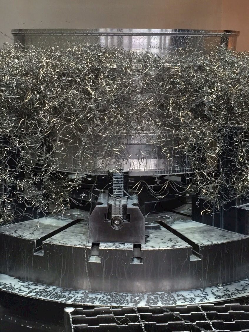
Long and continuous chips tend to have a negative effect on machining efficiency, with a risk of damage to the cutting tool, workpiece and machine tool. They can lead to unnecessary production stoppages because of chip-evacuation problems and create unsafe work conditions for the operator. These chips should be broken into small pieces for safety, easy removal and prevention of damage to the machine tool and workpiece.
There is also a traditional hand tool known as a router plane, a form of hand plane with a wide base and a narrow blade that extends well above the base plate. CNC wood routers add the benefits of Computer Numerical Control (CNC).
This type of router moves up and down on spring-loaded bars. You can adjust the cutting depth without having to turn off the router. You can also set it to make cuts at a number of different depths.
Serrated or segmented chips – also called non-continuous chips – are semi-continuous chips with large zones of low shear strain and small zones of high shear strain or shear localization. These types of chips appear when machining materials with low thermal conductivity and high strain-hardening tendencies. The material strength increases when the stress in the material increases, especially in combination with a higher temperature, as is the case with titanium. These chips display a saw-tooth appearance.
Chip thickness ratio is defined as the width of cut divided by the thickness of the chip. The depth of cut for a given feed should be large enough to avoid a too-small or too-large chip thickness ratio. Small depths of cut combined with certain feeds produce square chips. Overly small feeds can lead to ribbon-shaped chips that are unbreakable.
Shearing chips or short chips – also called discontinuous chips – consist of segments that are detached from each other. These chips form when cutting brittle workpiece materials such as bronze, hard brass and gray cast iron, as well as very hard materials or those with hard inclusions and impurities. Brittle materials lack the ductility necessary for appreciable plastic chip deformation. Repeated fracturing limits the amount of chip deformation.
Various groups of factors offer practical ways to influence chip formation, including cutting tools, cutting conditions, materials and cooling system.
Anyone looking for a new router for their DIY projects has probably noticed the wide range of different styles available. Home improvement will have to choose between a fixed base router or a plunge router, and some combo kits are also available. Get to know each type to choose the best one.
A wood router is a power tool with a flat base and a rotating blade extending past the base. The spindle can be driven by an electric motor or a pneumatic motor. It routs (hollowed out) an area in hard material, such as wood or plastic.
Run test cuts before routing your final piece. Use the same scrap wood and bit you plan to use on your project. Feed the router from right to left if the fence is between you and the router. Feed in the opposite direction if the router is between you and the fence.
Force-feeding gives a rough surface. It also leaves wavy lines called chatter marks. They’re unattractive and you’d need to sand them off for a smooth finish. Working slowly means you’ll have less to polish up when you’re done.
If you push the material with the spin of the blade, it’s called climb cutting. This is dangerous and should be avoided. The blade might pull the material from your hands. It could even pull your hands or fingers into the blade.
The impact of tool features on chip formation is a frequent topic of discussion. Of main importance here are the rake angle and cutting-edge angle, nose radius, and the geometry of the cutting edge and chip breaker. Larger rake angles, lower cutting-edge angles and a larger nose radius yield longer chips. The impact of the coating type on chip formation is not clearly definable.
Material factors include workpiece hardness and tensile strength, ductility and structural considerations. These elements cannot be modified to improve chip formation, but the machinist must consider their impact on chip formation.
Most wood routers have adjustable speeds, but make sure the speed range suits your needs. Some DIY enthusiasts may need a fixed base router to get a smooth edge, while others prefer a dip base model that can carve flutes and a groove into the workpiece.
The influence of cooling system on chip formation is rather arbitrary. It is very difficult to see fixed relationships between the type of cooling system and its impact on chip formation. One exception is the so-called HPDC (High Pressurized Directed Cooling) system, which clearly leads to much-shorter chips. This type of cooling system is applied in the Seco Jetstream tooling system.
There are two types of wood routers, one with a fixed base and one with a plunge base. On some models, you can switch between the two.
Deformation takes place along a narrow shear zone called the primary shear zone. Some continuous chips may develop a secondary shear zone at the tool/chip interface. This zone becomes thicker as friction increases. Continuous chips also may occur with a wide primary shear zone that displays curved boundaries. The lower boundary of the deformation zone – the side flow effect – can drop below the machined surface, which distorts the surface and leads to a poor surface finish.
Most plunge routers and fixed routers have a few basic things in common. The shank of a bit fits into a non-adjustable chuck on a router called a collet. You can get most types of burrs with either a 1/4 “or 1/2” shank.
If you’re working too fast, you’re force-feeding the router. Force-feeding stock means the bit touches the wood fewer times per cutting pass. Avoid doing this. It often bogs down the machine. Put another way, it slows down your router in a way that you can hear it struggling.
The housing allows controlled vertical movement during a cut, so you can plunge the drill into the surface of your workpiece without worrying.
The most practical way to influence chip formation is to modify cutting conditions, which can be very easy and effective to change. The basic cutting condition to adjust is chip thickness ratio or slenderness. When chip thickness ratio is too small, it produces so-called square chips that create overly high loads on the tool nose and thus limit tool life considerably. A too-high chip thickness ratio leads to slender ribbon-shaped chips that are very difficult to break into short pieces.
Fixed base routers are great for shaping edges because they are easy to maneuver. Fixed-base routers are considered good general-purpose routers.
In practice, depth of cut often is a given. In this situation, the feed forms the key to good chip formation. Avoid both overly low feeds that lead to long ribbon-shaped chips and overly high feeds that create square chips.
With a motor spinning bit over 20,000 rpm, a router can create shapes on the edge of a board or make raised panels for doors or trim.
Select chip-breaking geometries based on the type of operation, the combination of feed and depth of cut, and the type of workpiece material.
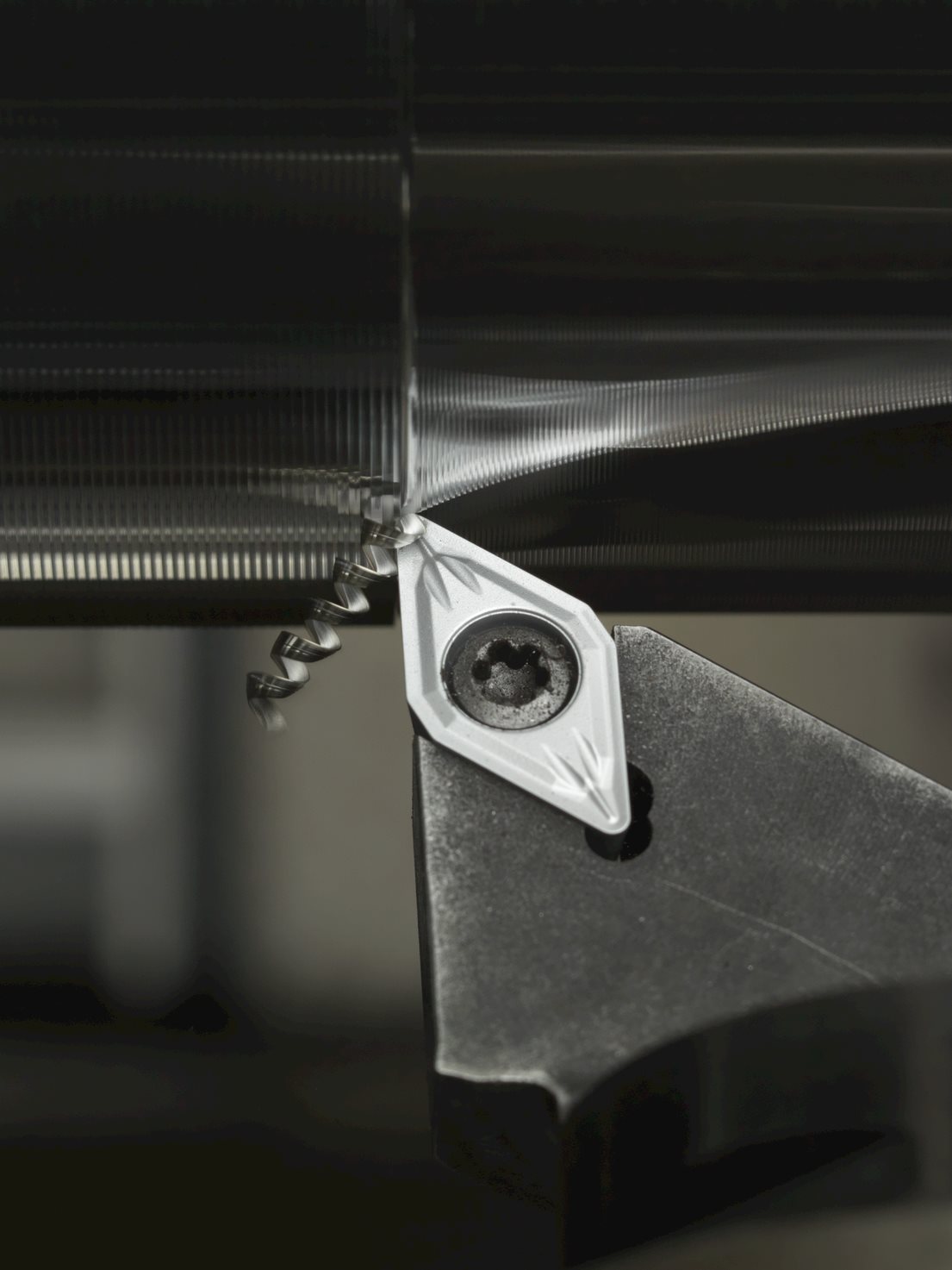
Continuous chips form when machining ductile materials, including mild steel, copper and aluminum. The plastic deformation of ductile material produces long, continuous chips, desirable from the perspective of cutting action because it produces good surface roughness with low power consumption and longer tool life. Continuous chips often form with a small chip thickness, high cutting speed, sharp cutting edge, large rake angle on the cutting tool, smooth tool face and an efficient lubricating system. These chips are difficult to handle and evacuate. They can coil in a very long spiral or helix shape that curls around the workpiece and tool and may injure the operator when the chip breaks. The tool face is in contact for a longer period, which produces more frictional heat. Chip breakers can rectify this problem.
Alternatively, router packages are available that allow you to swap bases, providing fixed-base and plunge-base capabilities in the same kit. Most of these combo kits switch quite easily, though they can be more expensive. Users won’t have to store two separate routers, but swapping bases can slow the workflow.
Together, both depth of cut and feed – the so-called chip thickness ratio – must remain between certain constraints. The maximum chip thickness ratio should remain below a certain maximum value to avoid too-long ribbon-shaped chips. The chip thickness ratio also should remain above a minimum value to avoid square chips. Figure 14 represents these constraints with two angled lines. The minimum and maximum value of the chip thickness ratio depends on workpiece material. To minimize broken cutting edges, the cutting forces should not rise too high. Figure 14 shows this constraint as a curved line.
Routers are most commonly used in woodworking, especially furniture making. They can be hand-held or attached to router tables. Some woodworkers consider the router to be one of the most versatile power tools available.
The vertical axis represents the type of application, ranging from finishing (small depths of cut) to roughing (large depths of cut). To some extent, the vertical axis represents relative depths of cut suitable for certain geometries. The actual size of the insert – the cutting-edge length – also influences the effective depth of cut. The various ISO-defined colors indicate which workpiece materials suit these geometries.
All chips have two surfaces. The outer surface displays a shiny, polished surface because it rubs – and causes wear – on the rake face of the tool. Every chip also has an inner surface formed by the original surface of the workpiece, with a jagged, rough appearance caused by the actual shearing mechanism.
In general terms, when the rake angle decreases (negative tooling), chip curvature becomes tighter, which leads to shorter, broken chips. Chip breakers serve to reduce the radius of chip curvature and thus break chips into shorter lengths.
Increased cutting speeds and rake angle, sharper tools, use of coolant and of a cutting material with lower chemical affinity for the workpiece material can reduce the formation of built-up edge.
A chip-breaking diagram (see Figure 14) can show the relationship among workpiece material, cutting conditions, chip-breaking geometry and chip formation. This diagram identifies the considerations involved in selecting depth of cut and feed to machine a specific workpiece material with a defined chip-breaking geometry. The horizontal axis represents the feed, which always must be larger than a certain minimum (the width of the T-land geometry) and should remain lower than a certain maximum (never larger than half the nose radius). The vertical axis shows the depth of cut, which always should be larger than the nose radius to promote good chip formation and avoid problems with square chips. Additionally, the depth of cut never should be larger than the cutting edge length. In the latter case, it is advisable to work with safety factors, which depend on the strength of the cutting edge. In the case of inserts, these safety factors vary between 75% (for square or rhombic inserts) and 20% (for copy inserts with a small top angle) of the cutting edge length.
Feed a table router slowly from right to left for best results. The wood goes in against the direction the blade is spinning. You should feel light to moderate resistance as you work. The resistance means the router is doing the work. Feed speed is determined by the wood and the type of cut you’re making.
This type of wood router conforms by sliding up and down in its base. It’s easy to customize and works well for on-site projects.
Tip: Listen to the machine. Any change in sound gives you clues. The pitch changes when you’re working the machine too hard by feeding too fast. The router may also sound different when your bit is dull and needs replacing. Over time, your ears can help guide your router technique.
Tip: If you are doing heavy routing with a 1/4-inch shank drill, make shallow cuts. Introduce the work slowly to avoid breaking the bit
Router bits that have bearings are called pilot bits. Pilot bits work in handheld or table-mounted routers. You can use them with or without a fence to guide the workpiece. Before using a router fence, make sure there is no wood waste on the work surface. Debris could interfere with the wood from lying flat and flush against the fence.
Make shallow passes for the smoothest results. Try to resist the urge to make a cut in a single pass. The larger the bit, the deeper the cut. Work even slower on harder materials. For a successful deep cut, you’ll need to make more shallow passes.
In general, to adjust the depth of cut on a fixed base router, loosen a locking knob and either rotate the base or adjust a knob. With a fixed base router, it’s a little easier to make subtle changes but harder to adjust on the go.
Understanding the answer to “What does a router do?” means properly using the tool. You could run a router quickly along a board to get done faster. However, if you take your time, the project will turn out much better.
Seasoned DIYers and hobbyists know the difference a wood router can make on the quality of the end product. From simple round overs to fancy ogee edges, the best wood router kicks up the results a notch.


 0086-813-8127573