
Full Radius Solid Carbide Keyseat Cutters - carbide keyseat cutter
Workpiece is held in a chuck, mounted on a face plate or secured between centers and rotated while a cutting tool, normally a single-point tool, is fed into it along its periphery or across its end or face. Takes the form of straight turning (cutting along the periphery of the workpiece); taper turning (creating a taper); step turning (turning different-size diameters on the same work); chamfering (beveling an edge or shoulder); facing (cutting on an end); turning threads (usually external but can be internal); roughing (high-volume metal removal); and finishing (final light cuts). Performed on lathes, turning centers, chucking machines, automatic screw machines and similar machines.
Space provided behind a tool’s land or relief to prevent rubbing and subsequent premature deterioration of the tool. See land; relief.
The mathematical expression denoting one of several parameters that describe surface texture (same as average roughness Ra). Average roughness is the arithmetic average height deviation of the measured surface profile from the profile centerline. See surface texture.
Milling insert specificationchart pdf
Replaceable tool that clamps into a tool body, drill, mill or other cutter body designed to accommodate inserts. Most inserts are made of cemented carbide. Often they are coated with a hard material. Other insert materials are ceramic, cermet, polycrystalline cubic boron nitride and polycrystalline diamond. The insert is used until dull, then indexed, or turned, to expose a fresh cutting edge. When the entire insert is dull, it is usually discarded. Some inserts can be resharpened.
DOC stands for Depth of Cut and is the depth the tool penetrates the material along its axis, perpendicular to the surface being machined. It's usually determined by the cutting-edge length of the tool and how much of the tool is engaged with the material.
The fifth position is a significant one- or two-digit number indicating the size of the inscribed circle (I.C.) for all inserts having a true I.C. such as Round, Square, Triangle, Trigon, Pentagon, Hexagon, Octagon, and Diamond. This position designates the number of eighths of an inch in the nominal size of the I.C. It will be a one-digit number when the number of eighths of an inch in the I.C. is a whole number: 1 – 1 ⁄ 8"; 2 – 1 ⁄ 4"; 3 – 3 ⁄ 8"; 4 – 1 ⁄ 2"; 5 – 5 ⁄ 8"; 6 – 3 ⁄ 4"; 7 – 7 ⁄ 8";
There are 16 standard shapes of indexable inserts, and each shape is identified by a capital letter as follows (Figure 1):
WOC stands for Width of Cut and it refers to the width of the material engaged by the cutting tool in the direction parallel to the workpiece surface. This depth is less than the tool's diameter.
Kennametal turninginsertnomenclature
The seventh position indicates the cutting point configuration: a radius or a facet. In the case of a radius, the number indicates how many of 1 ⁄ 64 of an inch in the radius: 0 – sharp corner (0.002" max. radius); 0.2 – 0.004"; 0.5 – 0.008"; 1 – 1 ⁄ 64"; 2 – 1 ⁄ 32"; 3 – 3 ⁄ 64"; 4 – 1 ⁄ 16"; 5 – 5 ⁄ 64"; 6 – 3 ⁄ 32"; 7 – 7 ⁄ 64"; 8 – 1 ⁄ 8"; 10 – 5 ⁄ 32"; 12 – 3 ⁄ 16" 14 – 7 ⁄ 32" = 14; 16 – 1 ⁄ 4"; X – Any other corner radius.
It is a two-digit number carried to one decimal place when it is not a whole number: 1.2 – 5 ⁄ 64"; 1.5 – 3 ⁄ 32"; 2.5 – 5 ⁄ 32"; 3.5 – 7 ⁄ 32".
The 10th position is only used if there are letters in the seventh position. It will be a significant number representing the nominal sixty-fourths of an inch in length of the primary facet: 1 – 1 ⁄ 64"; 2 – 1 ⁄ 32"; 3 – 3 ⁄ 64"; 4 – 1 ⁄ 16"; 5 – 5 ⁄ 64"; 6 – 3 ⁄ 32"; 7 – 7 ⁄ 64"; 8 – 1 ⁄ 8"; 9 – 9 ⁄ 64"; 10 – 5 ⁄ 32".
Explanation: Enter each code position to decode the specific insert characteristics according to ANSI B212.4-2002 standards.
Conditioning of the cutting edge, such as a honing or chamfering, to make it stronger and less susceptible to chipping. A chamfer is a bevel on the tool’s cutting edge; the angle is measured from the cutting face downward and generally varies from 25° to 45°. Honing is the process of rounding or blunting the cutting edge with abrasives, either manually or mechanically.
For all other polygons, dimension B is the distance, measured along the bisector of the rounded off corner angle and a gage roll of nominal I.C. size tangent to the two sides opposite the corner (Figure 2). For example, if a tolerance letter is H, tolerances on dimensions (± from nominal) are: 0.0005" on dimension A, 0.0005" on dimension B and 0.001" on dimension T.
Milling insert specificationchart
Tool that cuts a sloped depression at the top of a hole to permit a screw head or other object to rest flush with the surface of the workpiece.
Tolerances on dimensions (± from nominal) are denoted by letters A, B and T. Dimension A is the nominal inscribed circle (I.C.) of the insert. Dimension T is the thickness of the insert. For pentagon, triangle and trigon shapes, dimension B is the insert height, i.e., the distance between one side and the opposite corner (Figure 2).
Carbideinsertidentification chart
Inserts selection depends on workpiece material, chip control, surface finish, tool life, and the machine tool’s power and torque requirements. One of the commonly used indexable inserts for general turning is CNMG 432.
1. Shape (e.g., A, C, D): 2. Clearance (e.g., A, B, C): 3. Tolerance Class (e.g., A, B, C): 4. Type (e.g., A, B, C): 5. Size Code: 6. Thickness Code: 7. Cutting-Point Configuration (e.g., 0, 0.5, A): 8. Edge Preparation (e.g., A, B, C): 9. Hand (R, L, N): 10. Facet Size: Decode Insert
Due to the magazine’s space limitations, the authors provide the following tables showing most popular Kennametal’s indexable inserts only for general turning of steel, cast iron, and nonferrous alloys. These tables don’t cover all Kennametal chip breakers. (Figure 4 and Figure 5 also show Kennametal Inc. insert identification system and chip breaker identification system respectively.)
Space provided behind the cutting edges to prevent rubbing. Sometimes called primary relief. Secondary relief provides additional space behind primary relief. Relief on end teeth is axial relief; relief on side teeth is peripheral relief.
Milling insert specificationmetric
Now that you know how to calculate feeds and speeds, you can apply this knowledge by setting up your tool in Fusion 360 to proceed with the CAM operations. The next video demonstrates how to create your own tool library in Fusion 360.
It will be a two-digit number carried to one decimal place when it is not a whole number: 1.2 – 5 ⁄ 32"; 1.5 – 3 ⁄ 16"; 1.8 – 7 ⁄ 32"; 2.5 – 5 ⁄ 16".
American National Standard ANSI B212.4-2002 covers the identification system for indexable-type inserts for both single-point and multiple-point cutting tools. It was published on October 29, 2002. The earlier editions of the standard are:
This video provides a clear guide on how to calculate the feeds and speeds for a tool. The linked website offers valuable resources, including feed per tooth and surface meter per minute values, based on the tool and stock material to assist in determining the appropriate feeds and speeds.
On rectangular and parallelogram inserts, the width and length dimensions are used in place of the I.C. A two-digit number designates the sizes of these inserts. The first digit indicates the number of eighths of an inch in the width and the second digit indicates the number of fourths of an inch in the length of the insert.
There are 14 tolerance classes that control the indexability of the inserts. Each class is denoted by a capital letter. Letters for tolerances are A, B, C, D, E, F, G, H, J, K, L, M, U and N.

The selection of the DOC and WOC must balance efficiency and the need to minimize tool wear and potential damage to the workpiece. Deep cuts in the axial and radial axis can be more efficient but might lead to higher forces on the tool and workpiece, while shallow cuts are generally less efficient but can achieve better surface finishes and extend tool life.
Steelmilling insert specification
Edmund Isakov, Ph.D., is a consultant, writer and frequent CTE contributor. He is the author of the books “Mechanical Properties of Work Materials” (Modern Machine Shop Publications, 2000); “Engineering Formulas for Metalcutting” (Industrial Press, 2004); “Cutting Data for Turning of Steel” (Industrial Press, 2009); the CD-ROM “International System of Units (SI)” (Industrial Press, 2012); and the software “Advanced Metalcutting Calculators” (Industrial Press, 2005). For more information, call (561) 369-4063 or visit www.edmundisakovphd.com.
Angle of inclination between the face of the cutting tool and the workpiece. If the face of the tool lies in a plane through the axis of the workpiece, the tool is said to have a neutral, or zero, rake. If the inclination of the tool face makes the cutting edge more acute than when the rake angle is zero, the rake is positive. If the inclination of the tool face makes the cutting edge less acute or more blunt than when the rake angle is zero, the rake is negative.
Feeds and speeds are critical parameters in machining operations. Feeds refer to the rate at which the cutting tool advances through the material, typically measured in inches or mm per minute, and are essential for balancing material removal rates with effective chip clearance. Inadequate feed rates can lead to tool breakage or chip clogging. Speeds concern the spindle RPM (revolutions per minute), influencing tool temperature and wear. Proper spindle speeds prevent the tool from overheating, which can soften and dull the cutting edge, resulting in poor surface quality or tool failure. Both feeds and speeds are vital for optimizing tool life, enhancing machining efficiency, and ensuring superior surface finishes
Feed per tooth is the amount of material removed by each tooth of the cutter during one spindle revolution. This is usually measured in millimetres per tooth or inches per tooth. The appropriate value depends on the material being cut (such as metal, plastics, or plywood) and the type of cutter used (e.g., coated or uncoated carbide). You can typically find this information online.

Milling insert specificationexample
ANSI B212.4-2002 standard added one more capital letter O, which denotes other relief angles for new designs of indexable inserts.
Imaginary circle that touches all sides of an insert. Used to establish size. Measurements are in fractions of an inch and describe the diameter of the circle.
The sixth position is a significant one- or two-digit number indicating the number of sixteenths of an inch in the thickness of the insert. It is a one-digit number when the number of sixteenths of an inch in the thickness is a whole number: 1 – 1 ⁄ 16"; 2 – 1 ⁄ 8"; 3 – 3 ⁄ 16"; 4 – 1 ⁄ 4"; 5 – 5 ⁄ 16"; 6 – 3 ⁄ 8"; 7 – 7 ⁄ 16"; 8 – 1 ⁄ 2"; 9 – 9 ⁄ 16"; 10 – 5 ⁄ 8".
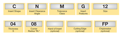
According to ANSI B212.4-2002 standard, identification of the indexable insert includes 10 positions denoted by a capital letter. Each position (from 1 to 10) defines a characteristic of the insert in the following order:
Milling insert specificationpdf
The fourth position is a capital letter denoting differences in design of insert, such as the existence of fixing holes, countersinks and special features on rake surfaces. There are 15 standard types in design as follows (Figure 3):
Surface Meter per Minute (SMM), similar to Surface Feet per Minute but using metric units, indicates the speed at which the tool's cutting edge moves relative to the material's surface. Like the feed per tooth, it varies depending on the material and the type of cutter used. This data is also available online.
1. Shape2. Clearance3. Tolerance class4. Type5. Size6. Thickness7. Cutting-point configuration8. Edge preparation9. Hand10. Facet size
In case of a facet, two letters are used. The first letter designates the facet angle: A – 45°; D – 60°; E – 75°; G – 87°; P – 90°; Z – Any other facet angle. The second letter designates the facet clearance angle:
About the Authors: Edmund Isakov, Ph.D., is a consultant, writer, and frequent CTE contributor. He is the author of four books “Mechanical Properties of Work Materials” (Modern Machine Shop Publications, 2000); “Engineering Formulas for Metalcutting” (Industrial Press, 2004); “Cutting Data for Turning of Steel” (Industrial Press, 2009); “International System of Units (SI)” the CD-ROM (Industrial Press, 2013); and the software “Advanced Metalcutting Calculators” (Industrial Press, 2005). For more information, call (561) 369-4063, or email: edmundisakov9701@comcast.net. Shi ‘Steve’ Chen is Manager Product Engineering Turning at Kennametal Inc. For more information, call (724) 539-5321, or email: Shi.Chen@Kennametal.com
Nine relief angle values have been described in ANSI B212.12-1991 standard. These angles are the difference from 90° measured in a plane normal to the cutting edge generated by the angle between the flank and top surface of the insert. Each relief angle is denoted by a capital letter as follows:


 0086-813-8127573