
Guide for Choosing Carbide Reamers: Types, Features, ... - what is a reamer used for
Boring ToolHolder
Similarly, tool holding also plays a vital role in the performance of a boring bar application. It is important to select a tool holder that accommodates the tooling being used and is as rigid as possible. Using an improper method of tool holding can lead to tool runout, which occurs when the tool or holder deviates too far off its axis.
www.harveytool.com www.helicaltool.com www.micro100.com www.titancuttingtools.com www.corehog.com www.valorholemaking.com
Lathe BoringBar Set
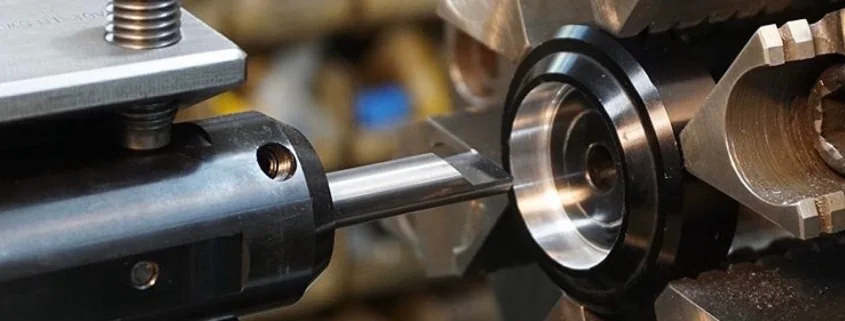
Before starting a boring application, drilling the proper hole is vital to ensuring that the boring bar has sufficient contact with the workpiece to properly stabilize the cut. If a hole is too large, the boring bar could deflect off of the workpiece. If the hole is too small, there will not be enough clearance for the tool, increasing chances of tool wear and possibly tool failure. When selecting a drill to prepare the workpiece for your boring applications, there are two dimensions that should be considered: the Head Width and the Minimum Bore Diameter.
Boringtools
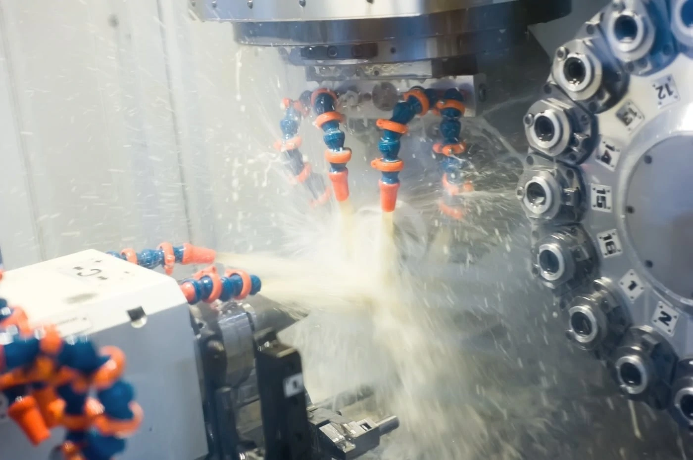
Machinists generally utilize Flood or High Pressure coolant methods for chip removal. Flood coolant uses low pressure to create lubricity and aid in chip evacuation. On the other hand, high pressure coolant delivers instant cooling of a part and quickly shoots chips away to prevent recutting.
We are getting into boring out a 2″ Id from composite fiber poles. We are reducing the id by .001 at a time and testing. The length of our cut will be about 15″ from the end of the tube. Can you offer what type of boring bar and insert would be best for us?
Lathe boringBar Holder
A main cause of chatter in boring applications is lack of support on the workpiece. If a workpiece is not properly supported when entering a boring application, the tool will begin to chatter. Not only is it essential to confirm the proper workholding device is being used, but it’s also important to ensure that your setup is as rigid as possible. Learn more about workholding styles and considerations to make sure you’re supporting your workpiece properly in your next boring application.
Boring tool in lathe machineprice
Boring with a worn-out tool significantly increases cutting forces generated by the cut, leading to chatter. The more a tool is run, the more chance it has for galling, or in other words, built-up edge (BUE), making it imperative to inspect your boring bar before each application. BUE occurs when material is welded onto the cutting tool due to high friction and heat generation during a CNC machining operation. This condition is not desirable because it leads to poor tool life and increased vibrations due to an uneven cutting edge. Stocking your tool crib with great quality boring bars can help reduce BUE by providing a sharp, long lasting cutting edge, catered for your exact application. Learn other ways to reduce BUE in your turning applications, today.
Thank you for reaching out, we would need a little more information about the job. Please send an email to [email protected] with all your information and they should respond to you shortly.
The Head Width, or “H” value on the above line drawing, is the actual width of the boring tool. The Minimum Bore Diameter is a calculated dimension slightly larger in size compared to the head with that is associated with the smallest drill size that should be used to start a boring application. It is recommended to opt for a drill that is the same or slightly larger than the Minimum Bore Diameter of the boring bar being used, to ensure there is proper clearance for the cutting edge.
A boring operation started at your optimal dia would pass through a too large, starter dia on the path to final dimension, wouldn’t?
Boring tool in lathe machinefor sale
Boring bar applications are very popular in the lathe and CNC machining industry, as they provide a shop with extreme diversity and accuracy. Running a boring bar properly, however, is essential to ensuring you’re maximizing shop efficiency and achieving outstanding part finish. There are many mistakes that can be made when running boring bars and many that cause excessive machining vibrations or chatter that must be avoided. Learn the five mistakes that could be causing tool chatter in your boring applications and how you can stop chatter once and for all.
Like many applications, using improper turning speeds & feeds can lead to poor performance. In boring applications, using too high of a chip load can cause deflection, greatly increasing the chances of tool failure. Using too low of a chip load doesn’t allow the tool to cut enough, which causes the tool to bounce off the material, leading to increased tool wear and poor part finish. Discovering the right balance for using chip load is crucial in order to produce a more efficient cut.

Bestboring tool in lathe machine
Many machinists opt for tools that promote machining efficiency by boosting the speed at which tool changes occur. For example cutting tool manufacturer Micro 100 offers Micro-Quik Holders, which offer unmatched rigidity, axial and radial repeatability, tip-to-tip consistency, and part-to-part accuracy in tool changes totaling fewer than 30 seconds.
Sign up to receive a monthly recap of: – The latest machining solutions – Machining tips and tricks – A recap of our most popular posts
When running a boring bar, it is imperative to use the speeds & feeds recommended for the tool being used. Micro 100 provides downloadable and printer-friendly Speeds & Feeds for all Standard and Quick Change Micro-Quik turning tools.
These face mills are designed with economical inserts, each with no less than 8 usable cutting edges, developed to reduce your overall machining costs. They are highly efficient milling cutters, with an 88° cutting edge angle, and chattering is reduced with low cutting force design. Applicable to various types of applications and materials.
How to useboring tool in lathe machine
If coolant isn’t aimed properly on the workpiece or if improper coolant is being used, tool life and quality part finish can be significantly reduced. Additionally, if coolant lines are aimed directly at the bore, the pressure of the coolant holds the chips in the bore, causing them to evacuate improperly. This then causes chip recutting, leading to chatter and finish problems. Opting for a Plumbed and Ported Tool Holder can mitigate this problem, ensuring chips are being properly evacuated out of the cut.


 0086-813-8127573