
Guide: How to choose the right CNC end mill - Mekanika - types of end mills
Roundchamfered edge
Hi! Thanks for your comment – we are currently working on converting more of our blog posts to PDFs. If you need a PDF of any of our posts while we work on this, you can click on the “Print” button, and many web browsers will give you the option to save the post as a PDF in the settings.
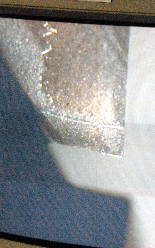
Thermal cracking is often identified by cracks in the tool perpendicular to the cutting edge. Cracks form slowly, but they can lead to both chipping and premature tool failure.
Introduction to High Efficiency Milling I High Speed Machining vs. HEM I How to Combat Chip Thinning I Diving into Depth of Cut I Intro to Trochoidal Milling
Filletedge
The number one way to get sheet metal parts made your way is to use your print, model, and RFQ to communicate clear specifications and expectations. When we thoroughly understand your goals and requirements, we’re empowered to not only achieve them but also recommend alternative solutions when we identify a better approach.
If the wear land becomes excessive or causes premature tool failure, reducing the cutting speed and optimizing coolant usage can help. Coolant is directed towards the cutting action of a tool during CNC operations. It prevents tool failure by countering high temperatures. Generally machinists opt for either Flood or High Pressure coolant methods. Flooding allows for low pressure chip flushing by providing lubricity. High Pressure coolant provides almost instant cooling of a part and works to evacuate chips at a faster rate. Both methods improve part finish and minimize chip recutting, which can damage a cutting tool.
Tool holder issues or loose work holding can also cause a fracture, as can inconsistencies in workpiece material properties. Establishing a secure connection between the tool and machine reduces the risk of tool runout and scrapped parts. Machinists generally experience improved performance in hydraulic and shrink fit tool holders compared to more mechanical tightening methods.
Chamfered edgewood
If chamfers and radii are not critical to your design, it is best not to dimension them on your print or model to avoid unnecessary costs. Instead, add a note to your print asking to “remove all sharp edges.” For critical dimensions, include them on your print, and ASM will ensure they are machined to meet precise specifications.
Chamfered edgevs roundededge
Sign up to receive a monthly recap of: – The latest machining solutions – Machining tips and tricks – A recap of our most popular posts
Whether your sheet metal parts need the angled edge of a chamfer or the rounded edge of a radius, there are a few things you should know.
Adjusting the speeds, feeds, and depth of cut and checking the setup for rigidity will help to reduce fracturing. The tool’s axial engagement with a part must be appropriate in order to prevent tool deflection, especially during slotting operations. As pictured below, with increasing slot lengths comes the necessity for longer lengths of cut. Above all, you should choose a tool that offers the highest productivity and least amount of deflection.
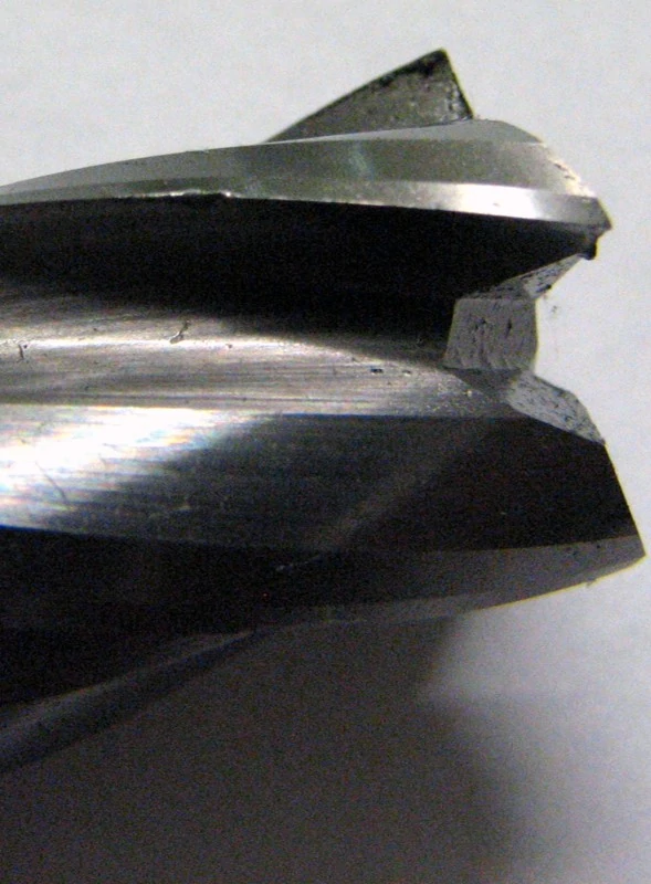
Chipping can be easily identified by a nicked or flaked edge on the cutting tool, or by examining the surface finish of a part. A poor surface finish can often indicate that a tool has experienced some sort of chipping, which can lead to eventual catastrophic tool failure if it is not caught. \When a chipped tool engages with a workpiece the cutting edges are not even leading to high and low spots within the surface finish.
Thermal cracking, as its name suggests, is caused by extreme temperature fluctuations during milling. Adding a proper coating to an end mill is beneficial in providing heat resistance and reduced abrasion on a tool.
Tool wear is the breakdown and gradual failure of a cutting tool due to regular operation. Every tool will experience tool wear at some point in its life. Excessive wear will show inconsistencies and have unwanted effects on your workpiece, so it is important to avoid tool wear in order to achieve optimal end mill performance. Tool wear can also lead to failure, which in turn can lead to serious damage, rework, and scrapped parts.
It is important to monitor tools and keep them in good, working condition to avoid downtime and save money. Wear is caused by both thermal and mechanical forces, which can be mitigated by running with appropriate running parameters and HEM toolpaths to spread wear over the entire length of cut. While every tool will eventually experience some sort of tool wear, the effects can be delayed by paying close attention to speeds and feeds and depth of cut. Preemptive action should be taken to correct issues before they cause complete tool failure.
The wear land is a pattern of uniform abrasion on the cutting edge of the tool, caused by mechanical abrasion from the workpiece. This dulls the cutting edge of a tool, and can even alter dimensions such as the tool diameter. At higher speeds, excessive heat becomes more of an issue, causing more damage to the cutting edge, especially when an appropriate tool coating is not used.
Chamfered edgemirror
High Efficiency Milling (HEM) toolpaths can help reduce wear by spreading the work done by the tool over its entire length of cut. This prevents localized wear and will prolong tool life by using the entire cutting edge available. The image referenced below compares traditional (standard) milling and the newer HEM method. HEM evenly disperses heat across the cutting edge by employing a lower radial depth of cut (RDOC) and a higher axial depth of cut (ADOC). This reduces the likelihood of tool failure and lengthens the tool wear process.
Bevelededge
Chamfers and radii are commonly requested features in custom sheet metal fabrication that can occasionally cause confusion.
To counter chipping, ensure the milling operation is completely free of vibration and chatter. Chatter occurs because cutting tools experience high forces during CNC machining operations. While machinists cannot entirely avoid chatter, minimizing it prevents vibration marks and excess wear from appearing along the surface of a tool or part. Taking a look at the speeds and feeds can also help. Interrupted cuts and repeated part entry can also have a negative impact on a tool. Reducing feed rates for these situations can mitigate the risk of chipping.
To ensure precision and accuracy, we’ll engage our CNC machine shop to machine the chamfers or radii. Though machining does add to a part’s cost and lead time, it’s the best process for achieving critical edge specifications and preventing part rejections during inspection.
ASM uses various methods to achieve chamfers and radii, including special punch tools, hand-filing, shaping with a dual-action sander, and tumbling. For edges with critical tolerances, machining is almost always the best and only solution to ensure precision and accuracy.
Chamfered edgedrywall
You can further your savings by removing the non-critical chamfers and radii from your 3D model, too. If you don’t do it, we will have to remove these design elements prior to programming our machines.
Good article… More folks should inspect their tooling and use high precision measurement equipment. The investment today, save $$$ in tool cost with profit gains from quality part output. Happy customers = more profitable repeat business.
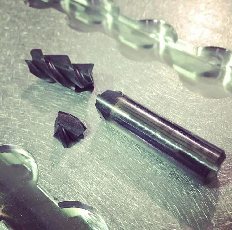
Fracture is the complete loss of tool usage due to sudden breakage, often as a result of improper speeds and feeds, an incorrect coating, or an inappropriate depth of cut.
To ensure your sheet metal parts meet your requirements, use your print, model, and RFQ to communicate clear specifications and expectations. Providing detailed information allows ASM to understand your goals, recommend alternative solutions, and deliver parts that meet your needs. Contact ASM to discuss your next custom sheet metal fabrication project and request a quote to get started.
At ASM, deburring is included as part of our standard processes, so if safety is your only focus, deburred metal edges are usually considered sufficiently smooth.
Hi Joe Click on the print icon for the article, when the print window pops up click on the down arrow in the Destination field. Look for “Save as PDF “, click on “Save as PDF”, and click save at the bottom of the window. You should then be able to choose where you would like to save the file on your computer.
www.harveytool.com www.helicaltool.com www.micro100.com www.titancuttingtools.com www.corehog.com www.valorholemaking.com
ASM can achieve chamfers and radii using various methods, such as special punch tools, hand-filing, or shaping with a dual-action sander. Tumbling can be an effective way of adding a radius to your part’s edges. For chamfered and rounded edges with critical tolerances, however, machining is almost always the best—and only—solution.
Thanks for going over some different types of wear that can happen. You mentioned that you need to make sure that, in order to prevent chipping, you need to make sure that the milling operation is free of vibration and chatter. It sounds like it’s beneficial to check for this on a regular basis so that you can make any adjustments as needed to make it stay in good condition.
Talk to our team about your next custom sheet metal fabrication project. Get started by requesting a quote, and we’ll be in touch with you soon!
The following is just one of several blog posts relevant to High Efficiency Milling. To achieve a full understanding of this popular machining method, view any of the additional HEM posts below!
If your sole goal is safety, the simplest way to get your part’s sharp edges removed is to ask. Just add a note to your print asking us to “remove all sharp edges”—and we will.
You could print it as a PDF. If you’re running W10 it’s an option under printing. If running something else, you’ll have to load a software like DOPDF to accomplish the same thing.
Chamfered edgetile
When enhanced safety and simplified assembly are important for your sheet metal parts, either chamfers or radii will do the trick. You don’t even need to dimension these features on your print or include them on your model. In fact, don’t dimension your edges—or we’ll quote you for critical dimensions you don’t actually need!
When we see that you’ve dimensioned the chamfers and radii on your print, we trust that those dimensions are critical and that you’ll inspect your parts in accordance with those dimensions.
Using a tool coating with a high microhardness rating is crucial to avoiding abrasive wear. Microhardness ratings help determine a cutting tool’s level of wear resistance. For example, bare tungsten carbide has a Vickers Hardness (HV) ranging from 760 HV to 1740 HV while coatings such as TiN have an HV of 2213 or more. Despite facing maximum forces during cutting operations, the addition of coating on a tool significantly improves its ease of material removal due to higher hardness. When hardness in a coating is elevated wear is mitigated due to the stack up.
This article is great.Nicely written and explained .Thanks for sharing this article.Yes you are absolutely correct .Its very important to monitor the tools and machines parts periodically to avoid any bigger problem.
To prolong tool life, identifying and mitigating the various signs of cutting tool wear is key. Both thermal and mechanical stresses cause tool wear, with heat and abrasion being the major culprits. Learning how to identify the most common types of tool wear and what causes them can help machinists remedy issues quickly and extend tool longevity.
HEM toolpaths provide excellent protection against thermal cracking. As previously mentioned, these toolpaths spread the heat across the cutting edge of the tool, reducing the overall temperature and preventing serious fluctuations in heat.
If safety is your main concern, simply request to have all sharp edges removed. ASM includes deburring as part of their standard processes, which is usually sufficient to achieve smooth and safe edges without additional specifications.
Chipping is typically caused by excessive loads and shock-loading during operation, but it can also be caused by thermal cracking, another type of tool wear which is explored in further detail below.
Optimizing coolant usage can also be helpful to avoid hot spots in materials which can dull a cutting edge and cause a fracture. HEM toolpaths prevent fracture by offering a more consistent load on a tool. Shock loading is reduced, causing less stress on a tool, which lessens the likelihood of breakage and increases tool life.
A chamfer is a 45-degree bevel cut across adjoining right angles, commonly used to create clearance for mating parts, simplify assembly, and eliminate sharp edges. A radius, on the other hand, replaces a raw corner with a rounded edge, improving safety and aesthetic appeal, and enhancing the fit of connecting parts.
Adding chamfers or radii to a part’s edges is a smart way to improve fit, eliminate unsafe edges, and enhance the part’s aesthetic appeal. So, what’s the difference between the two features?


 0086-813-8127573