
Harvey Tool - Find Your Specialty Carbide End Mills and ... - cutting wrench
GroovingTool Lathe
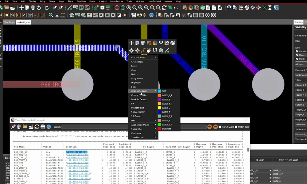
To ensure proper back drilling, it is necessary to provide the PCB board manufacturer with separate output files containing the back-drill layers, along with the specifications detailing which layers require corresponding back drilling. The diameter of the back drilling holes should be at least 0.2mm larger than the diameter of the first drill holes, and the distance between the back drilling through the layer and the trace should be 0.35mm for the first drill and 0.2mm for the back drilling. During PCB stack-up design, the dielectric thickness should be considered to avoid drilling into traces that should not be drilled. If drilling is required for a specific layer (such as layer “L”), the dielectric thickness between the adjacent layers that do not require drilling and layer “L” should be at least 0.2mm.
To provide a clearer explanation of the back drilling process, let’s consider an example. Suppose there is a 12-layer PCB with a through-hole connecting the first and 12th layers. The aim is to connect only the first layer to the 9th layer, while keeping the 10th to the 12th layers unconnected. However, the unconnected layers create “stubs” that can interfere with the signal path, resulting in signal integrity problems. Back drilling involves drilling out these stubs from the reverse side of the board to improve signal transmission.
ODGroovingtool
View South Texas Milling (www.stxmilling.com) location in Texas, United States , revenue, industry and description. Find related and similar companies as ...
One disadvantage of back drilling is that it is only appropriate for high-frequency boards with a frequency range between 1GHz and 3GHz and that do not have feasible blind vias. Additionally, a special technique must be used to prevent any harm to the traces and planes located laterally to the hole in the backboard.
May 7 - Now announcing UPS 2nd day air for one flat rate of $14.00. Some restrictions apply. Contact sales@internaltool.com for more details.
GroovingTool Holder
May 7 - Now announcing UPS 2nd day air for one flat rate of $14.00. Some restrictions apply. Contact sales@internaltool.com for more details.
Groovingmachine
So here comes the question: when to use back drilling? It is generally recommended to consider adding the technique when the circuit track on the PCB board has signals with a rate of ≥1Gbps. However, designing high-speed interconnection links is a complex system engineering task, and other factors such as the chip’s drive capability and the length of the interconnection links should also be considered. Therefore, the system interconnection link simulation is the most dependable approach to determine whether back drilling is required or not.

202443 — A lathe is a machine that shapes materials by spinning them against cutting tools. Lathes have gained popularity among professionals for their ability to do ...
There are many challenges in the design and manufacture of PCBs, one of which is to ensure signal integrity and high-speed data transfer rates, which are critical for high-frequency PCBs. It is worth mentioning that PCB back drilling can effectively solve this problem. In this article, we aim to give you a thorough overview of the back drilling technique, covering its definition, benefits, and drawbacks, the step-by-step process, and so on. Let’s just dive right in…
RadiusGrooving insert
Through-feed dies are designed without any lead angle (angle=0°) so that the part can feed. Their profile is made with annular grooves thus, the axes of the ...
OBJECTIVES. After completing this unit, you should be able to: ... Read this webpage from HAAS about G76 Threading Cycle, Multiple Pass (Group 00). G76 is the ...
... Action Soccer - Clearance Overstock - Welcome to Rodriguez Engraving. We help engrave words and images o. ... Double Action Soccer. Double Action Soccer. $32.75.
Beyond™ Evolution™ • Grooving Insert • GUP Geometry • Full Radius • Inch 100045543. ... Insert Size, 3. [W] Cutting Width, 3.302 mm. [W] Cutting Width .13 in.
Grooving InsertTool Holder
Spot weld removal drill bits. 3/8"-diameter, single-end, 2-pack.
Facegroovingtool
As an important method to ensure PCB signal integrity, back drilling is widely used in the PCB manufacturing process. Hope you can better understand and use this technology after reading this blog. If you have other questions, you can contact us and talk to one of our experts. As a leading PCB manufacturer in China, MOKO Technology has all the PCB expertise and skills needed to help you.

CERTIFICATE / LAB ; Round, 0.32, G ; Emerald, 0.31, F ; Emerald, 0.37, L ; Princess, 0.33, L ...
645-728 || 29/64 Diameter, Uncoated Reamers - 45 Degree Corner Chamfer.
Check out our new line of End mills, email info@internaltool.com for Details. This Featured tool is from our series 126 High Performance Aluminum Cutting Endmills. These are designed for roughing and finishing Aluminum Alloy material, they feature 3 Flutes, 45 Degree Helix, Variable Pitch, Full Eccentric Relief, and Zirconium coating.
IDGroovingTool
Aug 8, 2023 — HSS drill bits are typically made of steel mixed with other metals or elements, such as chrome. With their heavy-duty construction, they are ...
In addition, to optimize the back drilling process, it’s important to minimize the number of via stubs and avoid blind vias. Placing vias in less critical areas and maintaining a minimum distance between back drill holes and signal traces can also help prevent signal reflection and other issues. Keeping back drill hole diameters small is important to avoid damaging traces and planes lateral to the backboard hole. Additionally, considering back drilling during the initial design phase can help ensure that necessary steps are taken to optimize signal integrity and prevent problems during the manufacturing process.
10 Series Standard Boring bar now available with corner radius, AlTiN coating, and Tin Coating. Made from Solid Micro-grain Carbide, Tapered Neck and fillet radius provides maximum rigidity, All shanks have a lockdown flat for faster setups. These are made for boring all types of materials!
The process of PCB back drilling, also referred to as controlled depth drilling, involves removing the stub in multilayer PCBs to create vias. The aim of back drilling is to facilitate the flow of signals between different layers of the board without interference from unwanted stubs.


 0086-813-8127573