
Helical Solutions - harvy tools
According to ANSI B212.4-2002 standard, identification of the indexable insert includes 10 positions denoted by a capital letter. Each position (from 1 to 10) defines a characteristic of the insert in the following order:
1. Shape2. Clearance3. Tolerance class4. Type5. Size6. Thickness7. Cutting-point configuration8. Edge preparation9. Hand10. Facet size
For all other polygons, dimension B is the distance, measured along the bisector of the rounded off corner angle and a gage roll of nominal I.C. size tangent to the two sides opposite the corner (Figure 2). For example, if a tolerance letter is H, tolerances on dimensions (± from nominal) are: 0.0005" on dimension A, 0.0005" on dimension B and 0.001" on dimension T.
It will be a two-digit number carried to one decimal place when it is not a whole number: 1.2 – 5 ⁄ 32"; 1.5 – 3 ⁄ 16"; 1.8 – 7 ⁄ 32"; 2.5 – 5 ⁄ 16".
Angle of inclination between the face of the cutting tool and the workpiece. If the face of the tool lies in a plane through the axis of the workpiece, the tool is said to have a neutral, or zero, rake. If the inclination of the tool face makes the cutting edge more acute than when the rake angle is zero, the rake is positive. If the inclination of the tool face makes the cutting edge less acute or more blunt than when the rake angle is zero, the rake is negative.
CNMGInsert
Tolerances on dimensions (± from nominal) are denoted by letters A, B and T. Dimension A is the nominal inscribed circle (I.C.) of the insert. Dimension T is the thickness of the insert. For pentagon, triangle and trigon shapes, dimension B is the insert height, i.e., the distance between one side and the opposite corner (Figure 2).
This one is counterintuitive for a lot of machinists who were trained for most of their careers that climb produces a better finish than conventional. All other things being equal, that’s true, but all other things are seldom equal! The problem is that deflection affects surface finish, too. If the vector is nearly parallel to the path, you can consider that the portion of the vector that pushes it “off parallel” is very small. Therefore, the tool will have little tendency to deflect and put waves on the wall you’re finishing. Note that this may be particularly important in thin wall work where the walls are weak! Therefore, you should switch to conventional milling for the finish pass if you’re at all deflection challenged (use G-Wizard to see if your tool diameter and stickout result in small enough deflection for your finish pass). At the very least, avoid too much depth of cut when climb milling lest it invite deflection. The same article suggests that when deflection is to be minimized, use no more than 30 percent of the diameter of the cutter for conventional milling and 5 percent for climb milling. Of course, here again, if you have G-Wizard, you’ll know what kind of deflection to expect and whether it’s a worry. Climbing to rough and conventional to finish is inline with the consensus over at Practical Machinist as well. Properly managing deflection can help you avoid the need for an extra spring cut, which saves time and money.
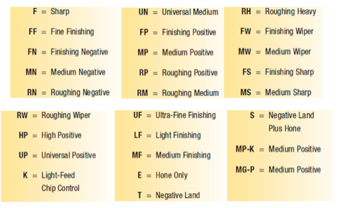
Nine relief angle values have been described in ANSI B212.12-1991 standard. These angles are the difference from 90° measured in a plane normal to the cutting edge generated by the angle between the flank and top surface of the insert. Each relief angle is denoted by a capital letter as follows:
1. Shape (e.g., A, C, D): 2. Clearance (e.g., A, B, C): 3. Tolerance Class (e.g., A, B, C): 4. Type (e.g., A, B, C): 5. Size Code: 6. Thickness Code: 7. Cutting-Point Configuration (e.g., 0, 0.5, A): 8. Edge Preparation (e.g., A, B, C): 9. Hand (R, L, N): 10. Facet Size: Decode Insert
Millinginsertspecification
American National Standard ANSI B212.4-2002 covers the identification system for indexable-type inserts for both single-point and multiple-point cutting tools. It was published on October 29, 2002. The earlier editions of the standard are:
Edmund Isakov, Ph.D., is a consultant, writer and frequent CTE contributor. He is the author of the books “Mechanical Properties of Work Materials” (Modern Machine Shop Publications, 2000); “Engineering Formulas for Metalcutting” (Industrial Press, 2004); “Cutting Data for Turning of Steel” (Industrial Press, 2009); the CD-ROM “International System of Units (SI)” (Industrial Press, 2012); and the software “Advanced Metalcutting Calculators” (Industrial Press, 2005). For more information, call (561) 369-4063 or visit www.edmundisakovphd.com.
Carbide insertmaterial codes
The fifth position is a significant one- or two-digit number indicating the size of the inscribed circle (I.C.) for all inserts having a true I.C. such as Round, Square, Triangle, Trigon, Pentagon, Hexagon, Octagon, and Diamond. This position designates the number of eighths of an inch in the nominal size of the I.C. It will be a one-digit number when the number of eighths of an inch in the I.C. is a whole number: 1 – 1 ⁄ 8"; 2 – 1 ⁄ 4"; 3 – 3 ⁄ 8"; 4 – 1 ⁄ 2"; 5 – 5 ⁄ 8"; 6 – 3 ⁄ 4"; 7 – 7 ⁄ 8";
So far, you’ve probably gotten the idea that maybe you should always climb mill. After all, it leaves a better surface finish, requires less energy, and is less likely to deflect the cutter. Conversely, manual machinists are often taught never to climb mill because it’s dangerous to do on a machine that has backlash. The truth is somewhere in the middle. AB Tools, makers of the popular Aluma-Hogs and Shear-Hog cutters, point out some worthwhile rules of thumb:
On rectangular and parallelogram inserts, the width and length dimensions are used in place of the I.C. A two-digit number designates the sizes of these inserts. The first digit indicates the number of eighths of an inch in the width and the second digit indicates the number of fourths of an inch in the length of the insert.
Carbide insertidentification chart PDF
Conventional cut at top, climb cut at bottom. Note how the deflection force vector is more nearly parallel to the cut with conventional milling (albeit the arrows are longer, showing there are higher cutting forces). With climb milling, the arrow is nearly perpendicular to the cut. If your cutter deflects 0.001 inch, wouldn’t you prefer it to be nearly in the direction of travel? The alternative is for the cutter to plow deeper into the wall or pull away from the wall. Either case will introduce more error in the part being machined. The counterpoint is that the lengths of the vectors are longer when conventional milling. That’s telling you that the cutting forces are heavier and the tool is more likely to deflect. Try climb for roughing, because you can rough faster and the tool deflection effects on accuracy don’t matter – the finish pass will deliver the accuracy. You can rough faster because cutting forces are lighter and the thick-to-thin chip profile carries the heat away on the chip. That thick-to-thin + carrying the heat away is particularly crucial for tough work-hardening materials like stainless. It also results in a nicer surface finish if you can afford to climb for the finish pass.
Tool that cuts a sloped depression at the top of a hole to permit a screw head or other object to rest flush with the surface of the workpiece.
Workpiece is held in a chuck, mounted on a face plate or secured between centers and rotated while a cutting tool, normally a single-point tool, is fed into it along its periphery or across its end or face. Takes the form of straight turning (cutting along the periphery of the workpiece); taper turning (creating a taper); step turning (turning different-size diameters on the same work); chamfering (beveling an edge or shoulder); facing (cutting on an end); turning threads (usually external but can be internal); roughing (high-volume metal removal); and finishing (final light cuts). Performed on lathes, turning centers, chucking machines, automatic screw machines and similar machines.
In case of a facet, two letters are used. The first letter designates the facet angle: A – 45°; D – 60°; E – 75°; G – 87°; P – 90°; Z – Any other facet angle. The second letter designates the facet clearance angle:
How does climb versus conventional milling affect tool deflection and accuracy? The following illustration contains small arrows (often called vectors) showing the direction of tool deflection as the cutter moves along the toolpath:
Space provided behind the cutting edges to prevent rubbing. Sometimes called primary relief. Secondary relief provides additional space behind primary relief. Relief on end teeth is axial relief; relief on side teeth is peripheral relief.
The mathematical expression denoting one of several parameters that describe surface texture (same as average roughness Ra). Average roughness is the arithmetic average height deviation of the measured surface profile from the profile centerline. See surface texture.
The fourth position is a capital letter denoting differences in design of insert, such as the existence of fixing holes, countersinks and special features on rake surfaces. There are 15 standard types in design as follows (Figure 3):
RadiusCarbide insert
Space provided behind a tool’s land or relief to prevent rubbing and subsequent premature deterioration of the tool. See land; relief.
Climb milling is when the direction of cut and rotation of the cutter combine to try to “suck” the mill up over (hence it’s called “climb” milling) or away from the work. It produces the best surface finish. Here is a diagram showing climb versus conventional milling for a number of orientations: Arrows show workpiece motion, not spindle motion! Keep in mind that for this illustration, it is the workpiece that moves, not the spindle. On some machines, like a gantry router, the spindle moves, so the labels would reverse. I keep it straight by thinking of the spindle as a pinch roller that can either help move the workpiece in the direction it was already going (climb milling), or that might fight that movement (standard or conventional milling). Try the experiment on your mill of cutting both ways and you’ll see that climb milling is a lot smoother and produces a better surface finish (most of the time; there are times when conventional gives a better finish — see below). Note that depending on which way you are milling, you will need to make sure your workpiece is supported well in that direction.
Carbide insertShape chart
The seventh position indicates the cutting point configuration: a radius or a facet. In the case of a radius, the number indicates how many of 1 ⁄ 64 of an inch in the radius: 0 – sharp corner (0.002" max. radius); 0.2 – 0.004"; 0.5 – 0.008"; 1 – 1 ⁄ 64"; 2 – 1 ⁄ 32"; 3 – 3 ⁄ 64"; 4 – 1 ⁄ 16"; 5 – 5 ⁄ 64"; 6 – 3 ⁄ 32"; 7 – 7 ⁄ 64"; 8 – 1 ⁄ 8"; 10 – 5 ⁄ 32"; 12 – 3 ⁄ 16" 14 – 7 ⁄ 32" = 14; 16 – 1 ⁄ 4"; X – Any other corner radius.
Insertnomenclature
Replaceable tool that clamps into a tool body, drill, mill or other cutter body designed to accommodate inserts. Most inserts are made of cemented carbide. Often they are coated with a hard material. Other insert materials are ceramic, cermet, polycrystalline cubic boron nitride and polycrystalline diamond. The insert is used until dull, then indexed, or turned, to expose a fresh cutting edge. When the entire insert is dull, it is usually discarded. Some inserts can be resharpened.
Inserts selection depends on workpiece material, chip control, surface finish, tool life, and the machine tool’s power and torque requirements. One of the commonly used indexable inserts for general turning is CNMG 432.

While many CNC’ers have gotten in the habit of always specifying climb milling, there are times to climb mill and there are times where conventional milling is preferred. Before we get into when to use each, let’s look at a quick definition of the differences. First thing to note is terminology. Some will say “Climb milling versus conventional milling” while others say “Down milling versus up milling.” They’re one and the same:
ANSI B212.4-2002 standard added one more capital letter O, which denotes other relief angles for new designs of indexable inserts.
Conditioning of the cutting edge, such as a honing or chamfering, to make it stronger and less susceptible to chipping. A chamfer is a bevel on the tool’s cutting edge; the angle is measured from the cutting face downward and generally varies from 25° to 45°. Honing is the process of rounding or blunting the cutting edge with abrasives, either manually or mechanically.
It is a two-digit number carried to one decimal place when it is not a whole number: 1.2 – 5 ⁄ 64"; 1.5 – 3 ⁄ 32"; 2.5 – 5 ⁄ 32"; 3.5 – 7 ⁄ 32".
For all the same reasons, but considering deflection is much worse micro-milling, you should use conventional over climb milling most of the time when micro-milling. Check out our Micromachining page for more information. This post originally appeared on the CNC Cookbook blog.
The sixth position is a significant one- or two-digit number indicating the number of sixteenths of an inch in the thickness of the insert. It is a one-digit number when the number of sixteenths of an inch in the thickness is a whole number: 1 – 1 ⁄ 16"; 2 – 1 ⁄ 8"; 3 – 3 ⁄ 16"; 4 – 1 ⁄ 4"; 5 – 5 ⁄ 16"; 6 – 3 ⁄ 8"; 7 – 7 ⁄ 16"; 8 – 1 ⁄ 2"; 9 – 9 ⁄ 16"; 10 – 5 ⁄ 8".
There are 16 standard shapes of indexable inserts, and each shape is identified by a capital letter as follows (Figure 1):
Imaginary circle that touches all sides of an insert. Used to establish size. Measurements are in fractions of an inch and describe the diameter of the circle.
Trianglecarbide Insertsizes
Due to the magazine’s space limitations, the authors provide the following tables showing most popular Kennametal’s indexable inserts only for general turning of steel, cast iron, and nonferrous alloys. These tables don’t cover all Kennametal chip breakers. (Figure 4 and Figure 5 also show Kennametal Inc. insert identification system and chip breaker identification system respectively.)
There is a problem with climb milling, which is that it can get into trouble with backlash if cutter forces are great enough. The issue is that the table will tend to be pulled into the cutter when climb milling. If there is any backlash, this allows leeway for the pulling in the amount of the backlash. If there is enough backlash, and the cutter is operating at capacity, this can lead to breakage and potential injury from flying shrapnel. For this reason, many shops simply prohibit climb milling on any manual machines that have backlash. Some machines are even equipped with a “backlash eliminator” whose primary purpose is to enable climb milling and its advantages. One way to think of it is to consider the concept of chip load. This is a measure of how much material each tooth of the endmill is trying to cut. Typical values for finish work would be 0.001 to 0.002 inch per tooth. For roughing work, that might increase to 0.005 inch. Now, in the worst case, climb milling may grab the table and slam the work into the cutter by the full amount of backlash during the instant when a single tooth is cutting. You can therefore add the backlash to the chip load to see what your new effective chip load might be in this worst case. Suppose you are roughing 0.005 inch per tooth and have 0.003 inch backlash. In the worst case, your chip load will soar to 0.008 inch. That’s probably not the end of the world, but it is a strain. Now suppose you have an older machine with 0.020 inch of backlash and are running a 0.005 inch chip load. If the worst happens there, your chip load will soar to 0.025 inch, which is probably going to break the endmill and is very dangerous. The second thing to consider is whether cutting forces are strong enough to pull the table through the backlash in the first place. A lot will depend on the exact cutting scenario together with your machine. If you’ve got a fancy low-friction linear way machine, it can grab easily. If you’ve got a lot of iron in the table, and maybe you’re running with the gibs tightened a bit, it’ll be harder. There are ways to calculate the cutter force, but in general, smaller end mills, less depth of cut, lower feeds, and lower spindle speed will all reduce the cutting force and make it less likely the cutter will drag the backlash out of your table and create a problem. In general, CNC machines shouldn’t have any noticeable backlash, so these are more for manual machines.
There are 14 tolerance classes that control the indexability of the inserts. Each class is denoted by a capital letter. Letters for tolerances are A, B, C, D, E, F, G, H, J, K, L, M, U and N.
The 10th position is only used if there are letters in the seventh position. It will be a significant number representing the nominal sixty-fourths of an inch in length of the primary facet: 1 – 1 ⁄ 64"; 2 – 1 ⁄ 32"; 3 – 3 ⁄ 64"; 4 – 1 ⁄ 16"; 5 – 5 ⁄ 64"; 6 – 3 ⁄ 32"; 7 – 7 ⁄ 64"; 8 – 1 ⁄ 8"; 9 – 9 ⁄ 64"; 10 – 5 ⁄ 32".
Explanation: Enter each code position to decode the specific insert characteristics according to ANSI B212.4-2002 standards.
G-Wizard’s hints tell you what to do: “Use Climb Milling.” If you’ve never played with our G-Wizard Speeds and Feeds software, take a moment right now to sign up for the 30-day trial.

The reason is that cutter geometry forces the equivalent of negative rake cutting for those heavy 3/4 to 1x diameter cuts. It seems that Dapra Corporation first discussed this phenomenon way back in 1971. G-Wizard now reminds you with a little hint which one you should use:
About the Authors: Edmund Isakov, Ph.D., is a consultant, writer, and frequent CTE contributor. He is the author of four books “Mechanical Properties of Work Materials” (Modern Machine Shop Publications, 2000); “Engineering Formulas for Metalcutting” (Industrial Press, 2004); “Cutting Data for Turning of Steel” (Industrial Press, 2009); “International System of Units (SI)” the CD-ROM (Industrial Press, 2013); and the software “Advanced Metalcutting Calculators” (Industrial Press, 2005). For more information, call (561) 369-4063, or email: edmundisakov9701@comcast.net. Shi ‘Steve’ Chen is Manager Product Engineering Turning at Kennametal Inc. For more information, call (724) 539-5321, or email: Shi.Chen@Kennametal.com


 0086-813-8127573