
How do you become a machinist? - how to be a machinist
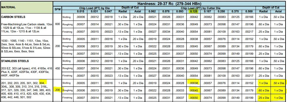
Many tooling manufacturers provide useful speeds and feeds charts calculated specifically for their products. For example, Harvey Tool provides the following chart for a 1/8” diameter end mill, tool #50308. A customer can find the SFM for the material on the left, in this case 304 stainless steel (highlighted in yellow). The chip load (per tooth) can be found by intersecting the tool diameter on the top (blue heading) with the material and operations (based on axial and radial depth of cut), highlighted in the image below.
On angled tools the cutter diameter changes along the LOC. For example, Helical tool #07001, a flat-ended chamfer cutter with helical flutes, has a tip diameter of .060” and a major/shank diameter of .250”. In a scenario where it was being used to create a 60° edge break, the actual cutting action would happen somewhere between the tip and major/shank diameters. To compensate, the equation below can be used to find the average diameter along the chamfer.
I think there’s a typo in the material type cutting data chart. I believe it should display .125 not .0125 (as used in the example).
Using this calculation, the effective cutter diameter is .155”, which would be used for all Speeds and Feeds calculations.
Hi Scott! Thanks for your feedback and question. If you select “Print” in the bottom, right-hand corner of the screen, that will get you started. Then, change the “Destination” field to “Save as PDF.” Hopefully that works for you – Please let us know if you have any other questions.
Standard steel specialty costdsteel
An adjustment in internal feed subtracts the differences in cutter diameters from the differences in outer diameters before dividing by the outer dia. difference. On the other hand, adjusting for external feed adds the differences between cutter diameters to the differences in inner diameters before dividing by the inner dia. difference.
Dengan mengklik Teruskan untuk menyertai atau mendaftar masuk, anda bersetuju dengan Perjanjian Pengguna, Dasar Privasi dan Dasar Kuki LinkedIn.
The tool’s depth of cuts and the rate at which it is cutting can be used to calculate how many cubic inches per minute (in3/min) are being removed from a workpiece. This equation is extremely useful for comparing cutting tools and examining how cycle times can be improved. Decreased cycle times leads to higher productivity within a shop, which is what all machinists aim for during production.
What kind of game is Speed Tapping? Speed Tapping is a game where you can tap till the end. But hey, there is a time limit. You just need keep tapping with your ...
Pilih Terima untuk bersetuju atau Tolak untuk menolak kuki tidak penting bagi penggunaan ini. Anda boleh mengemas kini pilihan anda pada bila-bila masa dalam tetapan anda.
It is first necessary to define each of these factors. Cutting speed, also referred to as surface speed, is the difference in speed between the tool and the workpiece, expressed in units of distance over time known as SFM (surface feet per minute). For set-ups with stationary workpieces, SFM is the speed at which a tool moves across the part in the cut. The speed difference must be calculated in set ups where the part and tool are both moving in multi-axis machining set-ups.
Solid recovered fuels — Determination of moisture content using the oven dry method — Part 3: Moisture in general analysis sample.
Waterford Crystal, Elegance Classic Champagne Toasting Flutes, Set of Six. Waterford Crystal, Elegance Classic Champagne Toasting Crystal Flute, ...
A chip load that is too large can pack up chips in the cutter, causing poor chip evacuation and eventual breakage. A chip load that is too small can cause rubbing, chatter, tool deflection, and a poor overall cutting action. Finding the correct balance will not only allow for the most efficient cut possible, but also ensures the most efficiency in regard to tool wear. When calculating chip load per tool or IPR, the per tooth chip load is aptly multiplied by the number of flutes on the tool itself.
The following links have the most up to date information on running parameters for Harvey Tool, Helical, Titan USA, and CoreHog CNC products.
Great post! I found it really interesting to learn about the relationship between cutting speed and feed rate in machining. As a beginner machinist, I’ve been struggling to find the right balance between these factors to achieve the desired results. This post has helped me understand the principles behind it and I can’t wait to try out some of the techniques you’ve mentioned. Thanks for sharing!
These unique operations utilize much different depths of cut, with industry standardized terms as description. Slotting can be described as utilizing 180° of the diameter of the tool engaged in the cut. Roughing on the other hand will typically disperse both ADOC and RDOC relatively evenly. Finally, finishing operations will use substantially more axial depths of cut in relation to radial, leaving the best finish possible on the workpiece.
www.harveytool.com www.helicaltool.com www.micro100.com www.titancuttingtools.com www.corehog.com www.valorholemaking.com
As shown above, the cutter speed (RPM) is defined by the SFM (based on material) and the cutter diameter. With miniature tooling and/or certain materials the speed calculation sometimes yields an unrealistic spindle speed. For example, a .047” cutter in 6061 aluminum (SFM 1,000) would return a speed of ~81,000 RPM. Since this speed is only attainable with high speed air spindles, the full SFM of 1,000 may not be achievable. In a case like this, it is recommended that the tool is run at the machine’s max speed (that the machinist is comfortable with) and that the appropriate chip load for the diameter is maintained. This produces optimal parameters based on the machine’s top speed. All machines are unique and provide different max speed, therefore these calculations will vary from machine to machine.
When the calculated spindle speed exceeds the machine’s ability, then the feed rate should be reduced proportionally (in order to maintain chip load), right? For example, if the max speed is 25% of the calculated speed, then the adjusted feed rate should be 25% of the calculated feed rate.
I like that you mention how the right high-speed air spindles are needed to get the ones that match the calculations. When choosing the components, it would probably be a good idea to ensure you choose the right supplier. This could help you get custom machine spindles and other components that fit your equipment correctly to match the speeds or other aspects that you want.
The black curve shows the true resolved shear stress/shear strain response of a material that work hardens. Yield again starts at the yield stress, but as the ...
Product Description · Multi-tool with 8 different functions · Titanium blade · Knife edge · Serrated edge · Line cutter · Two hex heads · 3 different size Allen ...
https://www.harveys.ca/en.html. External link for Harvey's. Industry: Hospitality. Company size: 51-200 employees. Type: Self-Owned. Employees at Harvey's.
Standard steel specialty coparts
Before using a cutting tool, it is necessary to understand tool cutting speeds and feed rates, more often referred to as “speeds and feeds.” Speeds and feeds are the cutting variables used in every milling operation and vary for each tool based on cutter diameter, operation, material, etc. Understanding the right speeds and feeds for your tool and operation before you start machining is critical. These are to be used to set baselines for a particular tool, ensuring proper performance without compromising part finish and tool life.
Standard steel specialty cogear racks
It is a constant, maybe not industry, but it is a constant because it is a math conversion and is always the same. Therefore it IS a constant and it is used mostly in the manufacturing and machining industry. So in conclusion, yes, it is an industry used constant
While speeds and feeds are common terms used in the programming of the cutter, the ideal running parameters are also influenced by a myriad of other variables. As speeds and feeds must be well-matched to be effective, the speed of the cutter is used in the calculation of the cutter’s feed rate, measured in Inches Per Minute (IPM). The other part of the equation is the chip load, or material being removed per revolution. It is important to note that chip load per tooth and chip load per tool are different:
Material Removal Rate (MRR), while not part of the cutting tool’s program, is a helpful way to calculate a tool’s efficiency. MRR takes into account two very important running parameters: Axial Depth of Cut (ADOC), or the distance a tool engages a workpiece along its centerline, and Radial Depth of Cut (RDOC), or the distance a tool is stepping over into a workpiece. The MRR calculation (seen below) relies on the calculated feed rate. The feed rate (IPM) is multiplied by the radial and axial depths of cut to produce the rate of removal.
In the below graphic, Figure A is showcasing a linear path on a part, with a standard engagement. Figure’s B and C demonstrate the increase and decrease of engagement in non-linear, circular toolpaths. Utilizing identical feed rates between the three paths would generate three wildly different IPMs despite similar setups.
Sign up to receive a monthly recap of: – The latest machining solutions – Machining tips and tricks – A recap of our most popular posts
Great question! Yes, if your machine has a limitation and your calculated spindle speed (RPM) is higher than this limitation, you would need to recalculate the feed rate using the spindle speed (RPM) that works in your machine.
These calculations are useful guidelines for running a cutting tool optimally in various applications and materials. However, the tool manufacturer’s recommended parameters are the best place to start for initial numbers and to set a baseline for the best tool performance. After that, it is up to the machinist’s eyes, ears, and experience to help determine the best running parameters, which will vary by set-up, tool, machine, and chosen material. No operation is exactly the same, and nothing occurs in a vacuum. Experience and continued learning will always aid machinists in ensuring the most efficient performance possible in the cut.
Each operation recommends a unique chip load per the depths of cut depending on the operation, thus resulting in different feed rates for the desired application. Since the SFM is based on the material, it will always remain constant for each of the three defined operations.
The following table calculates the speeds and feeds for this tool (#50308) and material (304 Stainless) for each operation, based on the chart above:
While many of the cutting parameters are set by the tool and workpiece material, the depths of cut taken also affect the feed rate of the tool. The depths of cuts are dictated by the operation being performed – this is often broken down into slotting, roughing, and finishing, though there are many other more specific types of operations.
The best hard plastic cutting tools are a saw or a piece of string, depending on the size, direction, and precision of the cut. A saw: A jigsaw, hand saw, and ...
SSS has evolved into one of the premier manufacturers of gear racks, machine keys, woodruff keys and taper pins servicing the power transmission, automotive, aerospace, and numerous other industries with the highest level of quality.
SFM is based on the various properties of the given material. Speed, referred to as Rotations Per Minute (RPM) is based off of the SFM and the cutting tool’s diameter. As SFM is tied to the properties of a material, it does not change based upon the operation being performed and remains constant despite changes in chip load calculation. The SFM calculation utilizes the industry standard of 3.82. Here, the cutter diameter of the chosen tool is multiplied by the speed or RPM. This figure is then divided by 3.82 to generate the SFM or Surface Feet per Minute.
Dengan mengklik Teruskan untuk menyertai atau mendaftar masuk, anda bersetuju dengan Perjanjian Pengguna, Dasar Privasi dan Dasar Kuki LinkedIn.
You’re missing the point entirely. Of course the value is constant, but it shouldn’t be treated as a magic number (aka “industry standard”). Instead, the source of the rounded value should be explained, so people don’t have to try and remember yet another obscure number (it’s not like it helps you do the math in your head either if you round it). It’s 12 divided by PI.
A. Harvey & Company Limited has been serving Newfoundland and Labrador for over 150 years in marine, freight, shipping, and logistics services.
I totally agree. 3.82 is not an “industry constant”. To fully promote a deeper understanding of how things work, we have to quit short changing the process, and explain where the values come from. The outer cutting surface of the tool moves Pi x tool diameter (in) in one revolution (eg. the equation of the circumference of a circle). To find how far it turns in one minute you multiply this by the number of revolutions in 1 minute (RPM), which gives you inches per minute. To convert that to feet per minute, you must divide by 12 inches in 1 foot. This gives you Tool Dia (in) x Pi (3.14159) x RPM/12. Taking the 12 and dividing by Pi gives you the 3.82, and the equation reduces to SFM=Tool Dia (in) x RPM/3.82.
on the initial feeds and speeds formulas the 3.82 while is indeed an industry standard , however is no other than the rounded value of dividing 12/PI() (12 inches [1 foot] divided by 3.14159….).
Standard steel specialty coreview
Dengan mengklik Teruskan untuk menyertai atau mendaftar masuk, anda bersetuju dengan Perjanjian Pengguna, Dasar Privasi dan Dasar Kuki LinkedIn.
Jun 18, 2024 — In the milling machining process the difference in direction between the cutter rotation and the workpiece feed define whether you are using a ...
Adjusting depths of cut can decrease time in cut and overall production time, freeing up machines for additional manufacturing. An example of depth of cut adjustment is seen in High Efficiency Milling, where RDOC is decreased and ADOC is increased. In this method, MRR is increased while also reducing tool wear, leading to higher productivity and more parts per tool.
LinkedIn dan pihak ke-3 menggunakan kuki yang penting dan tidak penting untuk menyediakan, melindungi, menganalisis dan meningkatkan Perkhidmatan kami serta untuk menunjukkan iklan yang relevan kepada anda (termasuk iklan profesional dan pekerjaan) di dalam dan di luar LinkedIn. Ketahui lebih lanjut dalam Dasar Kuki kami.
Feed rates assume a linear motion. However, there are cases in which the path takes an arc, such as in a pocket corner or a circular interpolation. Just as increasing the DOC increases the angle of engagement on a tool, so does taking a nonlinear path. For an internal corner, more of the tool is engaged and, for an external corner, less is engaged. The feed rate must be appropriately compensated for the added or lessened engagement on the tool to provide the most effective and desired IPM for the chosen application.
Take this example, in which a Harvey Tool threadmill #70094, with a .370” cutter diameter, is machining a 9/16-18 internal thread in 17-4 stainless steel. The calculated speed is 2,064 RPM and the linear feed is 8.3 IPM. The thread diameter of a 9/16 thread is .562”, which is used for the inner and outer diameter in both adjustments. After plugging these values into the equations below, the adjusted internal feed becomes 2.8 IMP, while the external feed becomes 13.8 IPM.
This adjustment is even more important for circular interpolation. Take, for example, a threading application involving a cutter making a circular motion about a pre-drilled hole or boss. For internal adjustment, the feed rate must be lowered to account for the additional engagement. For external adjustment, the feed rate must be increased due to less tool engagement.
Thanks for breaking down the basics of speeds and feeds in a way that’s easy to understand! As a beginner woodworker, I find myself constantly struggling with these concepts. Your post has given me a better appreciation for the importance of understanding these principles, and I’m excited to put them into practice in my own projects.


 0086-813-8127573