
Hurco CNC Machine Tools: Mills & Lathes - milling machine tool
Turningspeeds and feedscalculator
Pro Tool Reviews is a successful online publication that has been providing tool reviews and industry news since 2008. In today’s world of Internet news and online content, we found that more and more professionals researched a large majority of their major power tool purchases online. That piqued our interest.
Most metalworking books have nomograms or tables of spindle speeds and feed rates for different cutters and workpiece materials; similar tables are also likely available from the manufacturer of the cutter used.
One analogy would be a skateboard rider and a bicycle rider travelling side by side along the road. For a given surface speed (the speed of this pair along the road) the rotational speed (RPM) of their wheels (large for the skater and small for the bicycle rider) will be different. This rotational speed (RPM) is what we are calculating, given a fixed surface speed (speed along the road) and known values for their wheel sizes (cutter or workpiece).
Cutting speed may be defined as the rate at the workpiece surface, irrespective of the machining operation used. A cutting speed for mild steel of 100 ft/min is the same whether it is the speed of the cutter passing over the workpiece, such as in a turning operation, or the speed of the cutter moving past a workpiece, such as in a milling operation. The cutting conditions will affect the value of this surface speed for mild steel.
Spindle speed becomes important in the operation of routers, spindle moulders or shapers, and drills. Older and smaller routers often rotate at a fixed spindle speed, usually between 20,000 and 25,000 rpm. While these speeds are fine for small router bits, using larger bits, say more than 1-inch (25 mm) or 25 millimeters in diameter, can be dangerous and can lead to chatter. Larger routers now have variable speeds and larger bits require slower speed. Drilling wood generally uses higher spindle speeds than metal, and the speed is not as critical. However, larger diameter drill bits do require slower speeds to avoid burning.
The lead angle is an important factor in determining the efficiency of a worm and worm gear set. The efficiency increases with lead angle increase. For a given ...
Apr 11, 2024 — Harvey Industries International, Inc. Home · Knowledge base · Submit a ... If building mobile base, please ensure to leave tolerance to ensure ...
How to calculateFeed Rate for lathe
Machinability ratings can be used in conjunction with the Taylor tool life equation, VTn = C in order to determine cutting speeds or tool life. It is known that B1112 has a tool life of 60 minutes at a cutting speed of 100 sfpm. If a material has a machinability rating of 70%, it can be determined, with the above knowns, that in order to maintain the same tool life (60 minutes), the cutting speed must be 70 sfpm (assuming the same tooling is used).
In woodworking, the ideal feed rate is one that is slow enough not to bog down the motor, yet fast enough to avoid burning the material. Certain woods, such as black cherry and maple are more prone to burning than others. The right feed rate is usually obtained by "feel" if the material is hand fed, or by trial and error if a power feeder is used. In thicknessers (planers), the wood is usually fed automatically through rubber or corrugated steel rollers. Some of these machines allow varying the feed rate, usually by changing pulleys. A slower feed rate usually results in a finer surface as more cuts are made for any length of wood.
Excessive spindle speed will cause premature tool wear, breakages, and can cause tool chatter, all of which can lead to potentially dangerous conditions. Using the correct spindle speed for the material and tools will greatly enhance tool life and the quality of the surface finish.
Scientific study by Holz and De Leeuw of the Cincinnati Milling Machine Company[17] did for milling cutters what F. W. Taylor had done for single-point cutters.
Did you learn what you came for? If we didn’t answer your question, please leave us a comment and we’ll do our best to answer it for you!
A study on the effect of the variation of cutting parameters in the surface integrity in turning of an AISI 304 stainless steel revealed that the feed rate has the greatest impairing effect on the quality of the surface, and that besides the achievement of the desired roughness profile, it is necessary to analyze the effect of speed and feed on the creation of micropits and microdefects on the machined surface.[18] Moreover, they found that the conventional empirical relation that relates feed rate to roughness value does not fit adequately for low cutting speeds.
Finally, never, ever try to loosen the chuck by clamping it in a vice and pulling the trigger. With the force of some of today’s drills, even the strongest Pros don’t have the hand strength to keep the drill from whipping around and hurting their wrist and elbow.
When you’re installing a bit for the first time, loosen the chuck (clockwise) until it’s just wide enough to slip the drill bit into it. Then tighten it (counterclockwise) until you feel it begin to resist and then tighten a little more.
Some people refer to an impact driver as an impact drill. 10 years ago, we might have argued that it’s the wrong term. However, today there are 1/4-inch hex shank drill bits specifically designed to work with your impact driver. Technically, that makes it an impact drill.
How to calculatefeed rate for drilling
About Us Advertising Reprint Rights Tool Buying Guides Pro Tool Innovation Awards Tool Manufacturers and Tool Brands by Logo Pro Tool Reviews Writers and Editors Sign Up for Our Newsletter Contact Us Do Not Sell Or Share My Personal Information
Keyless chucks tighten and loosen by simply spinning the chuck’s outer housing. As you’re holding the drill with the chuck pointing away from you, spinning it counterclockwise tightens the jaws around your drill bit, and spinning it clockwise loosens it.
Feed per revolution Calculator
Millingspeeds and feedscalculator
Speeds and feeds have been studied scientifically since at least the 1890s. The work is typically done in engineering laboratories, with the funding coming from three basic roots: corporations, governments (including their militaries), and universities. All three types of institution have invested large amounts of money in the cause, often in collaborative partnerships. Examples of such work are highlighted below.
Titan USA's carbide precision cuting tools include endmills, drill mills, taps & dies. Contact Hemly Tool Supply for a quote today!

High Performance Chamfer Mill-0.1875" (3/16) Shank DIA x 60° per side - 4 Helical FL · VLR V100906. Brand: Valor Holemaking ...
Choosing the best oscillating multi-tool used to boil down to just a couple of brands. Not anymore. Advancements in battery, […]
The exact RPM is not always needed, a close approximation will work. For instance, a machinist may want to take the value of π {\displaystyle {\pi }} to be 3 if performing calculations by hand.
First, set the tip of the drill’s key into the matching hole on the chuck. You might have to give it a little turn so the teeth are able to slip together. From there, turn the key clockwise to loosen the chuck and counterclockwise to tighten it.
When calculating for copper alloys, the machine rating is arrived at by assuming the 100 rating of 600 SFM. For example, phosphorus bronze (grades A–D) has a machinability rating of 20. This means that phosphor bronze runs at 20% the speed of 600 SFM or 120 SFM. However, 165 SFM is generally accepted as the basic 100% rating for "grading steels".[12] Formula Cutting Speed (V)= [πDN]/1000 m/min Where D=Diameter of Workpiece in meter or millimeter N=Spindle Speed in rpm
e.g. for a cutting speed of 100 ft/min (a plain HSS steel cutter on mild steel) and diameter of 10 inches (the cutter or the work piece)
20141016 — I ordered a couple 5 flute carbide End Mills from Lakeshore Carbide that were made for Stainless Steel. I was given the recommended speeds ...
In milling, the depth of cut is two-dimensional. The Radial depth of cut (AE or RDOC), is the length that the tool engages a workpiece perpendicular to its ...
There are also collets with active bit ejection. They have a spring that pushes the bit out when you pull the collet so you don’t have to put your hands on a hot drill or driver bit.
METRIC SOLID CARBIDE END MILLS. Page 2. Visit fullertontool.com for the most ... Ball End End Mills. Universal End Mill - 4 Flutes. 3200 Ball. 35. Universal ...
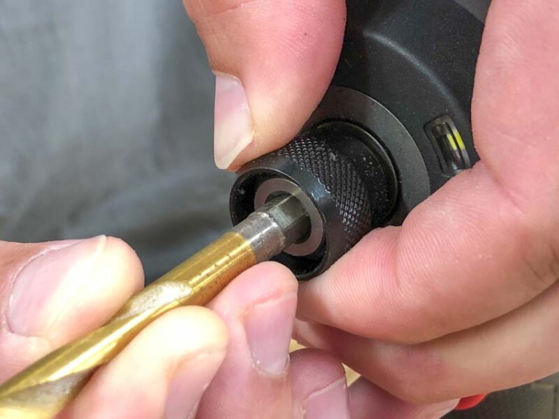
Instead of a chuck, an impact driver has a collet at the front. To change a drill bit, pull the outer part of the collet out to release the bit that’s in there. You also pull it out to install a new one. Easy peasy.
Even though most modern chucks are keyless, there are some keyed models running around. The overall principle is similar, though.
Generally speaking, spindle speeds and feed rates are less critical in woodworking than metalworking. Most woodworking machines including power saws such as circular saws and band saws, jointers, Thickness planers rotate at a fixed RPM. In those machines, cutting speed is regulated through the feed rate. The required feed rate can be extremely variable depending on the power of the motor, the hardness of the wood or other material being machined, and the sharpness of the cutting tool.
Cutting feeds and speeds, and the spindle speeds that are derived from them, are the ideal cutting conditions for a tool. If the conditions are less than ideal then adjustments are made to the spindle's speed, this adjustment is usually a reduction in RPM to the closest available speed, or one that is deemed (through knowledge and experience) to be correct.
There will be an optimum cutting speed for each material and set of machining conditions, and the spindle speed (RPM) can be calculated from this speed. Factors affecting the calculation of cutting speed are:
The spindle speeds may be calculated for all machining operations once the SFM or MPM is known. In most cases, we are dealing with a cylindrical object such as a milling cutter or a workpiece turning in a lathe so we need to determine the speed at the periphery of this round object. This speed at the periphery (of a point on the circumference, moving past a stationary point) will depend on the rotational speed (RPM) and diameter of the object.
Cutting speed (also called surface speed or simply speed) is the speed difference (relative velocity) between the cutting tool and the surface of the workpiece it is operating on. It is expressed in units of distance across the workpiece surface per unit of time, typically surface feet per minute (sfm) or meters per minute (m/min).[1] Feed rate (also often styled as a solid compound, feedrate, or called simply feed) is the relative velocity at which the cutter is advanced along the workpiece; its vector is perpendicular to the vector of cutting speed. Feed rate units depend on the motion of the tool and workpiece; when the workpiece rotates (e.g., in turning and boring), the units are almost always distance per spindle revolution (inches per revolution [in/rev or ipr] or millimeters per revolution [mm/rev]).[2] When the workpiece does not rotate (e.g., in milling), the units are typically distance per time (inches per minute [in/min or ipm] or millimeters per minute [mm/min]), although distance per revolution or per cutter tooth are also sometimes used.[2]
How to calculatefeed rate for milling
When deciding what feed rate to use for a certain cutting operation, the calculation is fairly straightforward for single-point cutting tools, because all of the cutting work is done at one point (done by "one tooth", as it were). With a milling machine or jointer, where multi-tipped/multi-fluted cutting tools are involved, then the desired feed rate becomes dependent on the number of teeth on the cutter, as well as the desired amount of material per tooth to cut (expressed as chip load). The greater the number of cutting edges, the higher the feed rate permissible: for a cutting edge to work efficiently it must remove sufficient material to cut rather than rub; it also must do its fair share of work.
Pro Tip: If you change a drill bit and it wobbles funny when you pull the trigger, it might not be centered between the jaws. Loosen the chuck and make sure all the teeth are engaging the bit as you clamp them back down.
Millingspeeds and feedsChart
For a given machining operation, the cutting speed will remain constant for most situations; therefore the spindle speed will also remain constant. However, facing, forming, parting off, and recess operations on a lathe or screw machine involve the machining of a constantly changing diameter. Ideally, this means changing the spindle speed as the cut advances across the face of the workpiece, producing constant surface speed (CSS). Mechanical arrangements to effect CSS have existed for centuries, but they were never applied commonly to machine tool control. In the pre-CNC era, the ideal of CSS was ignored for most work. For unusual work that demanded it, special pains were taken to achieve it. The introduction of CNC-controlled lathes has provided a practical, everyday solution via automated CSS Machining Process Monitoring and Control. By means of the machine's software and variable speed electric motors, the lathe can increase the RPM of the spindle as the cutter gets closer to the center of the part.
Schematically, speed at the workpiece surface can be thought of as the tangential speed at the tool-cutter interface, that is, how fast the material moves past the cutting edge of the tool, although "which surface to focus on" is a topic with several valid answers. In drilling and milling, the outside diameter of the tool is the widely agreed surface. In turning and boring, the surface can be defined on either side of the depth of cut, that is, either the starting surface or the ending surface, with neither definition being "wrong" as long as the people involved understand the difference. An experienced machinist summed this up succinctly as "the diameter I am turning from" versus "the diameter I am turning to."[4] He uses the "from", not the "to", and explains why, while acknowledging that some others do not. The logic of focusing on the largest diameter involved (OD of drill or end mill, starting diameter of turned workpiece) is that this is where the highest tangential speed is, with the most heat generation, which is the main driver of tool wear.[4]
The phrase speeds and feeds or feeds and speeds refers to two separate parameters in machine tool practice, cutting speed and feed rate. They are often considered as a pair because of their combined effect on the cutting process. Each, however, can also be considered and analyzed in its own right.
Sometimes, a drill chuck can be so tight on a drill bit that it’s difficult to loosen it. In this case, your best bet is to grab a pair of adjustable pliers (Channellocks). Set them to a width that grabs the outside of the chuck and use the additional leverage from the handles to loosen it.
Kenny holds a B.S. in Biology and a minor in chemistry. While that might not sound like a direct line into the power tool industry, his analytical and scientific mindset helps him design repeatable testing methods for Pro Tool Reviews’ head-to-head testing and offers highly objective comparisons in his reviews.
The spindle speed is the rotational frequency of the spindle of the machine, measured in revolutions per minute (RPM). The preferred speed is determined by working backward from the desired surface speed (sfm or m/min) and incorporating the diameter (of workpiece or cutter).
This formula[14] can be used to figure out the feed rate that the cutter travels into or around the work. This would apply to cutters on a milling machine, drill press and a number of other machine tools. This is not to be used on the lathe for turning operations, as the feed rate on a lathe is given as feed per revolution.
"Following World War II, many new alloys were developed. New standards were needed to increase [U.S.] American productivity. Metcut Research Associates, with technical support from the Air Force Materials Laboratory and the Army Science and Technology Laboratory, published the first Machining Data Handbook in 1966. The recommended speeds and feeds provided in this book were the result of extensive testing to determine optimum tool life under controlled conditions for every material of the day, operation and hardness."[4]
Some impact drivers have upgrades that make the process even easier. There are designs with one-hand bit insertion that let you slide the bit in without having to pull the collet.
By far the most common type of drill chuck today is a keyless chuck. Chances are, the answer to your question is in this section. Unlike your dad or grandpa’s old drill that had a funky-shaped key clamped to the cord, keyless chucks require no tools at all.
Speed-and-feed selection is analogous to other examples of applied science, such as meteorology or pharmacology, in that the theoretical modeling is necessary and useful but can never fully predict the reality of specific cases because of the massively multivariate environment. Just as weather forecasts or drug dosages can be modeled with fair accuracy, but never with complete certainty, machinists can predict with charts and formulas the approximate speed and feed values that will work best on a particular job, but cannot know the exact optimal values until running the job. In CNC machining, usually the programmer programs speeds and feedrates that are as maximally tuned as calculations and general guidelines can supply. The operator then fine-tunes the values while running the machine, based on sights, sounds, smells, temperatures, tolerance holding, and tool tip lifespan. Under proper management, the revised values are captured for future use, so that when a program is run again later, this work need not be duplicated.
In the 1890s through 1910s, Frederick Winslow Taylor performed turning experiments[16] that became famous (and seminal). He developed Taylor's Equation for Tool Life Expectancy.
The machinability rating of a material attempts to quantify the machinability of various materials. It is expressed as a percentage or a normalized value. The American Iron and Steel Institute (AISI) determined machinability ratings for a wide variety of materials by running turning tests at 180 surface feet per minute (sfpm). It then arbitrarily assigned 160 Brinell B1112 steel a machinability rating of 100%. The machinability rating is determined by measuring the weighed averages of the normal cutting speed, surface finish, and tool life for each material. Note that a material with a machinability rating less than 100% would be more difficult to machine than B1112 and material and a value more than 100% would be easier.
Shop MISUMI Ram Ball Custom Size Straight Flute End Mills at MISUMI. MISUMI offers FREE CAD download, short lead times and competitive pricing.
The cutting speed is given as a set of constants that are available from the material manufacturer or supplier. The most common materials are available in reference books or charts, but will always be subject to adjustment depending on the cutting conditions. The following table gives the cutting speeds for a selection of common materials under one set of conditions. The conditions are a tool life of 1 hour, dry cutting (no coolant), and at medium feeds, so they may appear to be incorrect depending on circumstances. These cutting speeds may change if, for instance, adequate coolant is available or an improved grade of HSS is used (such as one that includes [cobalt]).
Cutting speed and feed rate come together with depth of cut to determine the material removal rate, which is the volume of workpiece material (metal, wood, plastic, etc.) that can be removed per time unit.
Some materials, such as machinable wax, can be cut at a wide variety of spindle speeds, while others, such as stainless steel require much more careful control as the cutting speed is critical, to avoid overheating both the cutter and workpiece. Stainless steel is one material that hardens very easily under cold working, therefore insufficient feed rate or incorrect spindle speed can lead to less than ideal cutting conditions as the work piece will quickly harden and resist the tool's cutting action. The liberal application of cutting fluid can improve these cutting conditions; however, the correct selection of speeds is the critical factor.
Feed rate formula for turning
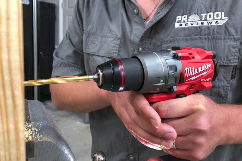
Want to know more about the drill and impact driver we featured in this article? Check out the details on Milwaukee’s 4th generation M18 Fuel Hammer Drill and Impact Driver!
Outside of the context of machine tooling, "speeds and feeds" can be used colloquially to refer to the technical details of a product or process.[3]
Grinding wheels are designed to be run at a maximum safe speed, the spindle speed of the grinding machine may be variable but this should only be changed with due attention to the safe working speed of the wheel. As a wheel wears it will decrease in diameter, and its effective cutting speed will be reduced. Some grinders have the provision to increase the spindle speed, which corrects for this loss of cutting ability; however, increasing the speed beyond the wheels rating will destroy the wheel and create a serious hazard to life and limb.
As a general rule, each finishing tool firms the soil surface, reduces hard surface clods and seals moisture. Finishing tools feature a simple ratchet screw ...
Some drill chucks have a ratcheting mechanism to help. If your drill does, you’ll feel and hear it clicking as the jaws tighten around the bit.
Feed rate is the velocity at which the cutter is fed, that is, advanced against the workpiece. It is expressed in units of distance per revolution for turning and boring (typically inches per revolution [ipr] or millimeters per revolution). It can be expressed thus for milling also, but it is often expressed in units of distance per time for milling (typically inches per minute [ipm] or millimeters per minute), with considerations of how many teeth (or flutes) the cutter has then determined what that means for each tooth.
Three warnings, though. All-metal chucks are pretty durable, but you can damage plastic ones with your adjustable pliers if you put too much force on the chuck.
Milwaukee Builds on Previous Tape Measure Success with Improved Durability, Precision, and Features Never content to rest on their laurels, […]
The ratio of the spindle speed and the feed rate controls how aggressive the cut is, and the nature of the swarf formed.
Learning how to change a drill bit is very similar whether you have a Milwaukee, DeWalt, Black & Decker, Craftsman, Ryobi, or another brand of drill. However, there are several types depending on how you’re using the term “drill”. No matter what type you have, this guide can teach you what you need to know.
If variables such as cutter geometry and the rigidity of the machine tool and its tooling setup could be ideally maximized (and reduced to negligible constants), then only a lack of power (that is, kilowatts or horsepower) available to the spindle would prevent the use of the maximum possible speeds and feeds for any given workpiece material and cutter material. Of course, in reality those other variables are dynamic and not negligible, but there is still a correlation between power available and feeds and speeds employed. In practice, lack of rigidity is usually the limiting constraint.
As with meteorology and pharmacology, however, the interrelationship of theory and practice has been developing over decades as the theory part of the balance becomes more advanced thanks to information technology. For example, an effort called the Machine Tool Genome Project is working toward providing the computer modeling (simulation) needed to predict optimal speed-and-feed combinations for particular setups in any internet-connected shop with less local experimentation and testing.[15] Instead of the only option being the measuring and testing of the behavior of its own equipment, it will benefit from others' experience and simulation; in a sense, rather than 'reinventing a wheel', it will be able to 'make better use of existing wheels already developed by others in remote locations'.
2022228 — A lathe is a simplistic device, designed to hold a section of material as a turning tool carves, cuts or shapes it. This is called the workpiece.


 0086-813-8127573