
Indexable & Solid End Mills - mill tooling
2. Tool holder The tool holder is mounted on the tool holder rail of the bed and can be moved longitudinally along the guide rail. The tool holder component consists of several layers of tool holders. Its function is to clamp the turning tool for longitudinal, lateral or oblique feed motion.
The main parameter of the horizontal lathe is the maximum rotary diameter of the workpiece on the bed, and the second is the maximum length of the workpiece. These two parameters indicate the maximum limit size of the workpiece machined by the lathe, and also reflect the size of the machine tool, because the main parameters determine the height of the axis of the spindle from the guide rail of the lathe body, and the second main parameters determine the length of the lathe bed.
The main motion of the engine lathe is the rotation motion of the spindle, and the feed motion is the linear movement of the tool. Feed is usually expressed by the movement of the tool per spindle, in M / R. When turning threads, there is only one compound main motion, namely screw motion, which can be decomposed into spindle rotation motion and tool movement. If you want faster thread processing, or you have large number of workpieces need to be mass-produced then CNC pipe threading lathe is a good choice. In addition, there are some necessary auxiliary movements on the lathe. For example, in order to process the wool to the required size, the lathe should also have the cutting motion (the cutting motion is usually perpendicular to the direction of feed motion, and the worker moves the tool holder by hand on the horizontal lathe). Some lathes also have the rapid longitudinal and lateral movement of the tool holder.
We also use different external services like Google Webfonts, Google Maps, and external Video providers. Since these providers may collect personal data like your IP address we allow you to block them here. Please be aware that this might heavily reduce the functionality and appearance of our site. Changes will take effect once you reload the page.
Modified stubacme threaddimensions
Click on the different category headings to find out more. You can also change some of your preferences. Note that blocking some types of cookies may impact your experience on our websites and the services we are able to offer.
I. Spindle box The headstock is fixed to the left end of the bed, and the main shaft and the variable speed transmission mechanism are installed inside, and the workpiece is clamped to the front end of the spindle through the chuck. The function of the headstock is to support the main shaft and transmit the power to the main shaft via the variable speed transmission mechanism, so that the main shaft drives the workpiece to rotate at a prescribed speed to realize the main motion.
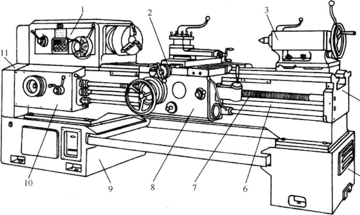
Horizontal lathe mainly processes various kinds of axle, sleeve and disk parts. Its shape is shown in the figure, and its main group is composed of three parts. Components include spindle box, tool holder, tailstock, feed box, slide box and bed, etc.
Because these cookies are strictly necessary to deliver the website, refusing them will have impact how our site functions. You always can block or delete cookies by changing your browser settings and force blocking all cookies on this website. But this will always prompt you to accept/refuse cookies when revisiting our site.
UNFthread
1.1 Fill the machine grease diagram with the appropriate grease. 1.2 Check the electrical facilities of each department, the handle, transmission parts, protection and limit devices are complete and reliable. 1.3 Each gear should be at zero position, and the belt should be tight. 1.4 The bed surface is not allowed to directly store metal objects to avoid damage to the bed surface. 1.5 The workpiece to be processed, no muddy sand, prevent mud sand from falling into the carriage, and grinding the guide rail. 1.6 Before the workpiece is clamped, the empty lathe test run must be carried out to confirm that everything is normal before the workpiece can be loaded.
We provide you with a list of stored cookies on your computer in our domain so you can check what we stored. Due to security reasons we are not able to show or modify cookies from other domains. You can check these in your browser security settings.
2.5 The workpiece, tool and fixture must be securely mounted. The floating force tool must extend the knife part into the workpiece to start the machine. 2.6 When using the center frame or the tool holder, the center must be adjusted and well lubricated and supported. 2.7 When processing long materials, the protruding part behind the spindle should not be too long. If it is too long, the loading frame should be installed and the danger mark should be hung. 2.8 When feeding, the knife should be close to work to avoid collision; the speed of the carriage should be even. When changing a tool, the tool must be at an appropriate distance from the workpiece. 2.9 The cutting tool must be fastened, and the length of the turning tool is generally not more than 2.5 times the thickness of the knife. 2.1.0 When machining eccentric parts, it is necessary to have an appropriate counterweight to balance the center of gravity of the chuck and the speed of the vehicle should be appropriate. 2.1.1. If the card is beyond the workpiece outside the fuselage, protective measures must be taken. 2.1.2 The adjustment of the tool setting must be slow. When the tool tip is 40-60 mm away from the workpiece processing position, manual or work feed should be used instead of direct feed. 2.1.3 When honing the workpiece with a file, the tool holder should be retracted to a safe position. The operator should face the chuck with the right hand in front and the left hand in the back. The workpiece with the key groove on the surface is not allowed to be processed with a file. 2.1.4 When the outer circle of the workpiece is polished with an abrasive cloth, the operator shall light the two ends of the abrasive cloth according to the posture specified in the above article. Do not use a finger to hold the abrasive cloth to polish the inner hole. 2.1.5 When the tool is automatically moved, the small tool holder should be adjusted to be flush with the base to prevent the base from hitting the chuck. 2.1.6 When cutting large or heavy workpieces or materials, sufficient machining allowance should be left.
2.1 When the workpiece is good, start the lubricating oil pump first, so that the oil pressure can reach the requirements of the machine tool before starting. 2.2 When adjusting the exchange carrier, when the wheel is adjusted, the power must be cut off. After the adjustment, all the bolts must be tightened, the wrench should be removed in time, and the workpiece should be taken off for trial operation. 2.3 Immediately after loading and unloading the workpiece, remove the floating wrench of the chuck wrench and the workpiece. 2.4 The tailstock and crank handle of the machine tool should be adjusted to the appropriate position according to the processing needs, and tightened or clamped.
We may request cookies to be set on your device. We use cookies to let us know when you visit our websites, how you interact with us, to enrich your user experience, and to customize your relationship with our website.
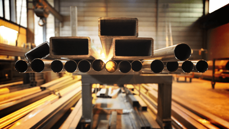
Horizontal metal lathe has a wide range of technology. It can process many kinds of surface, such as inner and outer cylinder, cone, ring groove, forming revolving surface, end plane and various threads. It can also drill, enlarge, compare holes and knurl. The typical surface that a horizontal lathe can process is shown in the figure.
These cookies are strictly necessary to provide you with services available through our website and to use some of its features.
3.1 Turn off the power and remove the workpiece. 3.2 Each handle is knocked down to zero position, and the tools are cleaned and cleaned. 3.3 Check the condition of each protection device.
Acme thread
We fully respect if you want to refuse cookies but to avoid asking you again and again kindly allow us to store a cookie for that. You are free to opt out any time or opt in for other cookies to get a better experience. If you refuse cookies we will remove all set cookies in our domain.
Lathes are mainly used to process rotating surfaces, and can perform turning, drilling, boring, threading, etc. These operations are widely used in various machining occasions, including manufacturing parts, repairing mechanical equipment, etc. Knowing more about different types of machining processes can help you master metalworking technology more comprehensively.
4. Bed The bed is mounted on the left and right leg legs and functions to support the main components and maintain an accurate relative position or trajectory during operation.
The tools used on the lathe are mainly lathe tools. They can also be used to process holes such as drills, reaming drills, dumpling knives, as well as threaded tools such as taps and plate teeth.
Gage Crib Worldwide, Inc. 6701 Old 28th St SE, Suite B Grand Rapids, MI 49546-6937 Phone: 001-616-954-6581 • Fax: 001-616-954-6583 CONTACT FORMS & INFO
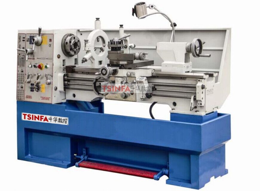
Lathe Machine is the most widely used type of machine tool in mechanical rapid manufacturing. There are a lot of fields that need lathe machines, they can be used in plastic mold, metal tooling, and other industry. The lathe machine accounts for about 20% – 35% of the total number of machine tools. It mainly processes various rotary surfaces (inner and outer cylinders, conical surfaces, shaped rotary surfaces, etc.) and the end surfaces of the rotary bodies. Some lathes can also process threaded surfaces.
6. Feed box The feed box is fixed to the left front side of the bed, and has a feed mechanism changing mechanism for changing the feed of the motor feed or the lead of the machined thread.
3. Tailstock The tailstock is mounted on the tool holder rail of the bed and can be adjusted longitudinally along the rail. Its function is to support the long workpiece with the top tip, or to install a hole machining tool such as a drill bit or a dumpling knife for hole machining. Install the bit on the tailstock, The workpiece can be drilled to make the lathe function as a radial drilling machine here.
Horizontal lathe shape 1 headstock 2 knife holder 3 tailstock 4 bed 5 right bed legs 6 light bar 7 screw 8 sliding box 9 left leg 10 feeding box 11 hanging wheel mechanism
5. Slide box The slide box is fixed at the bottom of the tool holder to move the tool holder together in the longitudinal direction. Its role is to pass the feed box through the light bar. The motion from (or the lead screw) is transmitted to the tool holder, allowing the tool holder to achieve longitudinal feed, lateral feed, rapid movement or threading. The joystick is equipped with various joysticks or buttons.


 0086-813-8127573