
ISO 20079:2005 - Duckweed growth inhibition test - 20079
T = gauge thickness or bit diameter.
Speeds and feedsformula
For general purpose machining, use a recommended feed rate of .005 – .020 inches per revolution for roughing and a .002 – .004 inches per revolution for finishing.
Millingspeeds and feedsChart
Find company research, competitor information, contact details & financial data for Tri-V Tool & Mfg. Co. of Omaha, NE. Get the latest business insights ...
5. Roughing cuts (0.01 in. to 0.03 in. depth of cut) for most aluminum alloys run at a feedrate of .005 inches per minute (IPM) to 0.02 IPM while finishing cuts (0.002 in. to 0.012 in. depth of cut) run at 0.002 IPM to 0.004 IPM.
The recommended feeds for cutting various materials when using a high speed steel cutting tools listed in table below. For general purpose machining a .005 – .020 inch feed for roughing and a .012 to .004 inch feed for finishing is recommended.
Drill, countersink or counterbore all in one operation to a high degree of accuracy. This six piece drill/countersink/counterbore features 1/4" hex shanked ...
Carbide end Mill RPM chart
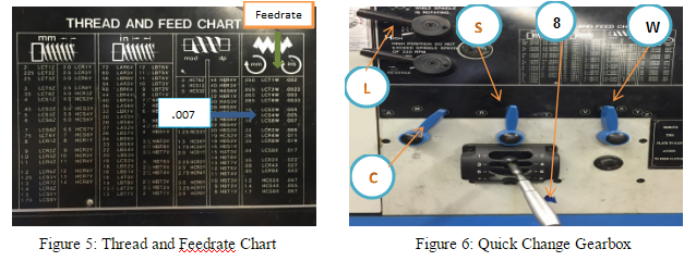
7.W = Select Feed Ranges and change to W on this lever (See Figure 3) Before turning on the lathe, be sure all levers are fully engaged by turning the headstock spindle by hand, and see that the feed rod turns.
Ask MetaFilter is a question and answer site that covers nearly any question on earth, where members help each other solve problems. Ask MetaFilter is where thousands of life's little questions are answered.
Feed rate formula
It has been my experience to take at least three cuts. One to remove excess material quickly: the rough cut, one cut to establish finish and to allow for tool pressure, and one to finish the cut.
We can control the feed on an engine lathe by using the change gears in the quick-change gearbox. Our textbook recommends whenever possible, only two cuts should be taken to bring a diameter to size: a roughing cut and a finishing cut.
Have you noticed that when you take a very small cut on the lathe .001 to .002 that the finish is usually poor, and that on the rough cut you made prior to this very light cut, the finish was good? The reason for this is: some tool pressure is desirable when making finish cuts.
Cutting speed formula
Millingspeeds and feedschart pdf
A lathe work cutting speed may be defined as the rate at which a point on the work circumference travels past the cutting tool. Cutting speed is always expressed in meters per minute (m/min) or in feet per minute (ft/min.) industry demands that machining operations be performed as quickly as possible; therefore current cutting speeds must be used for the type of material being cut. If a cutting speed is too high, the cutting tool edge breaks down rapidly, resulting in time lost recondition the tool. With too slow a cutting speed, time will be lost for the machining operation, resulting in low production rates. Based on research and testing by steel and cutting tool manufacturers, see lathe cutting speed table below. The cutting speeds for high speed steel listed below are recommended for efficient metal removal rates. These speeds may be varied slightly to shift factors such as the condition of the machine, the type of work material and sand or hard spots in the metal. The RPM at which the lathe should be set for cutting metals is as follows:
The feed of a lathe is the distance the cutting tool advances along the length of the work for every revolution of the spindle. For example, if the lathe is set for a .020 inch feed, the cutting tool will travel the length of the work .020 inch for every complete turn that work makes. The feed of a lathe is dependent upon the speed of the lead screw or feed rod. The speed is controlled by the change gears in the quick change gearbox.
To operate any machine efficiently, the machinist must learn the importance of cutting speeds and feeds. A lot of time can be lost if the machines are not set at the proper speed and feeds for the workpiece.
Aluminum milling speed chart
The lathes are designed to operate at various spindle speeds for machining of different materials. There speeds are measured in RPM (revolutions per minute) and are changed by the cone pulleys or gear levels. One a belt-driven lathe, various speeds are obtained by changing the flat belt and the back gear drive. One the geared-head lathe speeds are changed by moving the speed levers into proper positions according to the RPM chart fastened to the lathe machine (mostly on headstock). While shifting the lever positions, place one hand on the faceplate or chuck, and form the face plate slowly by hand. This will enable the levers for engage the gear teeth without clashing. Never change speeds when the lathe is running on lathers equipped with variable speed drivers, the speed is changed by turning a dial of handle while he machine is running.
4. What would the RPM be if we were turning a 1.00” diameter workpiece made out of mild steel, using Carbide cutting tool?
Example: Material = Aluminum 3” Cutter, 5 Teeth Chip Load = 0.018 per tooth RPM = 3000 IPS = 0.018 × 5 × 3000 = 270 Inches Per Minute
ZCTA5 45678 is a ZIP Code Tabulation Area located in Ohio.
... pen (Schon DSGN Dexter style) as it is made matt, there can be tumble marks on the surface of the pen, this is unavoidable. As each pen is colored by hand ...
A general discussion on plastic cutting tool geometry can be started by dividing plastic into three general categories: hard, soft, and reinforced.
Whenever possible, only two cut should be taken to bring a diameter cut. Since the purpose of a rough cut is to remove excess material quickly and surface finish is not too important. A coarse feed should be used. The finishing cut is used to bring the diameter to size and produce a good surface finish and therefore a fine feed should be used.
6. As the softness of the material decreases, the cutting speed increases. Additionally, as the cutting tool material becomes stronger, the cutting speed increases.
Speeds and Feedschart
In addition to ensuring that delicate waxes can be removed without distortion, the mold cutter must cut the mold in such a way that the two halves will match up ...
If you were cutting thread all day long: day in and day out. You might set the lathe up for only two cuts. One cut to remove all but .002 or .003 of material and the last cut to hold size and finish. This is done all the time in some shops today.
The chuck is the part of the drill that attaches the drill bit. Most power drills for home use have a 3/8-inch or 1/2-inch chuck. Larger chucks come in 5/8-inch ...
4. Feed rate and cutting speed are mostly determined by the material that’s being cut. In addition, the deepness of the cut, size and condition of the lathe, and rigidity of the lathe should still be considered.
The feed of on lathe, or the distance the carriage will travel in on revolution of the spindle, depends on the speed of the feed rod or lead screw. This is controlled by the change gears in the quick-change gearbox. This quick change gearbox obtains its drive from the head stock spindle through the end gear train. A feeds and thread chart mounted on the front of the quick-change gearbox indicates the various feeds and metric pitches or thread per inch which may be obtained by setting levers to the positions indicated.
Mar 20, 2024 — Feed rate measures how quickly the cutting tool moves along the workpiece, or how much distance the cutting tool covers for every revolution of ...
In order to eliminate this time loss, we can, and should, use recommended metal-removal rates that have been researched and tested by steel and cutting-tool manufactures. We can find these cutting speeds and metal removal rates in our appendix or in the Machinery’s Handbook.
Cheap Rebar Y8 Y10 Y12 B500c Steel Bars 10mm 12mm 16mm 18mm 20mm Rebars Steel Wholesale Price, Find Details and Price about Rebar Steel Rebar from Cheap ...
Manufacturing Processes 4-5 Copyright © by LamNgeun Virasak is licensed under a Creative Commons Attribution 4.0 International License, except where otherwise noted.


 0086-813-8127573