
ISO 20267:2017 - Thermal spraying — Determination of ... - 20267
Carbide end MillRPM chart

While counterbores and countersinks are similar in concept, they serve slightly different purposes. A countersink creates a conical recess for the screw head, while a counterbore creates a cylindrical recess for the bolt head.
First, lookup the recommended surface speed in Table 1 (V ≈ 250 ft/min) and calculate the spindle speed from Equation 2:
First, lookup the recommended surface speed in Table 1 (V ≈ 100 ft/min) and calculate the spindle speed from Equation 2:
Note: since applying oil manually, scale the speeds back to 60%, so NALUM ≈ 1425 rpm and NSTEEL ≈ 570 rpm (final answer). Note these are MAXIMUM values and lathe chuck safety must take precedence; spinning the lathe chuck at 570 rpm is about the upper limit of what we safely do in the lab, so for smaller or easier to machine workpieces, DO NOT EXCEED 600 RPM regardless of the calculation results, unless you are running a collet chuck.
Please begin by reviewing the comprehensive course document on this topic, as it clearly explains the process of calculating these parameters for drilling and milling operations. The governing equations are summarized below.
TIP: IF this was being performed on a CNC lathe, typical parting feed rates vary between 0.001 in/rev (for steels) and 0.005 in/rev (for plastics). But remember, do NOT use the power feed when parting on a manual lathe unless you own the machine!
HSSend mill Speeds and FeedsChart
First, lookup the recommended surface speed in Table 1 (V ≈ 625 ft/min) and calculate the spindle speed from Equation 2:
TIP2: When drilling deeper holes (> 3xD) without high pressure TSC (thru spindle coolant), reduce spindle speed an additional 50%.
A countersink is a tool used to create a conical recess at the top of a hole, allowing the head of a screw or fastener to sit flush with or below the surface of the workpiece. Countersinks typically have a conical cutting end with multiple cutting edges. They come in various angles, commonly 60° and 90°, to match the type of screws or fasteners being used. Countersinks are used in applications where a smooth, finished appearance is desired, and where the protrusion of screw heads could interfere with other components. They are commonly used in woodworking, metalworking, and construction projects.
TIP1: Recommended peck depth when drilling less than 3xD (e.g. 3 drill diameters) with flooded coolant is one drill diameter, or when applying oil manually, or under low pressure, is 50% of drill diameter.
TIP: Reamers should generally be run at half the spindle speed and twice the feed per revolution of the equivalent sized drill bit.
Example 4: Calculate the speed and feed for a 1″ diameter, 6 flute HSS annular cutter in ¼ thick aluminum on a manual milling machine in the lab.
The table below contains a recommended surface speeds for common materials when using DML equipment. These values are conservative because our primary goal is fostering a safe learning environment (for our users and our tools!), not trying to squeeze every second out of each operation.
Countersinks and chamfer tools are available in different materials, including high-speed steel (HSS), carbide, and cobalt, to accommodate various workpiece materials, from softwoods and plastics to metals like steel, aluminum, and stainless steel.
Some counterbores have depth control features, such as adjustable depth stops, to ensure consistent depth across multiple workpieces.
Tool Design: A counterbore consists of a cylindrical shank and a cutting head. The cutting head has a flat bottom and may include multiple cutting edges or flutes. The diameter of the counterbore corresponds to the size of the fastener being used.
Millingspeeds and feedsChart Metric
Example 2B: Calculate the speed and feed for a 1/2″ diameter, 3 flute carbide endmill if peripheral and plunge cutting in aluminum using a CNC milling machine in lab.
Every metal cutting operation requires selection of proper cutting parameters for success. As a DML TA, you need to understand basic calculations that will allow the tools you use to work as intended.
The primary purpose of a counterbore is to create a recess for the head of a screw or bolt, allowing it to sit flush with the workpiece surface. This prevents the fastener head from protruding and interfering with other components.
First, lookup the recommended surface speed in Table 1 (V ≈ 250 ft/min) and calculate the spindle speed from Equation 2:
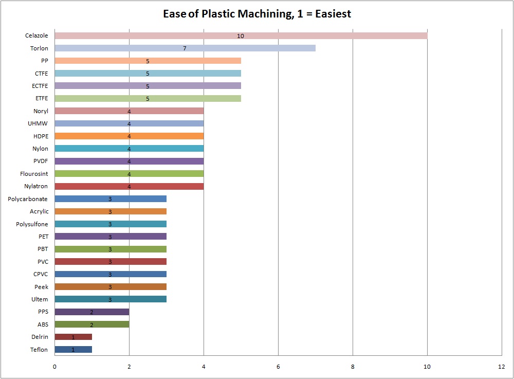
As you can see Acetal (Delrin) is one of the most machinable plastics and nylon is four times less machinable (which is why it should usually be avoided!).
End Mill Speeds and Feedschart
A chamfer tool, also known as a chamfer mill or chamfer cutter, is used to create a beveled edge or chamfer along the edge of a workpiece or a hole. Chamfers are often applied to remove sharp edges, prevent chipping, or allow for easier insertion of parts. Chamfer tools come in various shapes and angles, such as 45°, 60°, and 90°, to produce different chamfer profiles. They are used in a wide range of industries, including automotive, aerospace, electronics, and woodworking.
Note that these speed and feed values are guidelines assuming adequate (flooded) lubrication and workpiece stiffness. When applying oil manually (as in the lab), scale the feed and speed back to 60%, so N = 330 rpm and f = 2.0 in/min (final answer).
Example 2A: Calculate the speed and feed for a 1″ diameter, 4 flute HSS endmill in aluminum using a manual milling machine in lab.
Counterbores can be used with hand tools, such as handheld drills, or with power tools like drill presses and milling machines for more precise and efficient machining.
TIP: Countersinking should generally be performed at 25% of the speed and the same feed per revolution as the equivalent sized drill.
TIP: When working with plastics with good machinability, use the cutting parameters for aluminum up until the point that the plastic melts.
In CNC machining, countersinks and chamfer tools are often integrated into tool changers and used alongside other cutting tools for more complex machining operations.
First, lookup the recommended surface speed in Table 1 for a 1 HSS endmill cutting aluminum (V ≈ 250 ft/min) and calculate the spindle speed from Equation 2 using the aforementioned 75% speed reduction:
In addition to creating recesses for fastener heads, counterbores can also be used for chamfering or deburring purposes.
Countersinks and chamfer tools are cutting tools used in metalworking, woodworking, and other machining processes to create beveled edges, chamfers, or conical recesses on the surface of a workpiece. These tools serve various purposes, such as enhancing the appearance of edges, improving fitment, or facilitating screw or fastener insertion. Here's an overview of countersinks and chamfer tools:
Next lookup the recommended feed per revolution for the drill bit in Table 2 (fr ≈ 0.004 in/rev) and calculate the feed rate using Equation 3:
Counterbores are available in various materials, including high-speed steel (HSS) and carbide, to accommodate different workpiece materials, from wood and plastics to metals.
Note that these speed and feed values are guidelines assuming proper (flooded) lubrication, workpiece stiffness and depth of cut. When applying oil manually (as in the lab), scale the feed and speed back to 60%, so N = 570 rpm and f ≈ 18 in/min (final answer). Note also this problem assumes we peripheral milling versus plunge milling (since we never teach the students the latter in lab).
Lathefeeds and speedsChart
There are different types of countersinks, including single-flute, multi-flute, and adjustable countersinks. Single-flute countersinks are suitable for softer materials, while multi-flute countersinks offer improved chip evacuation and better surface finish in harder materials.
Next, lookup the recommended feed per tooth (chipload) in Table 3 (ft ≈ 0.008 in/tooth) and calculate the feed rate using Equation 3:
Next, calculate the feed rate used for plunging. Remember annular cutters should be fed at approximately 25% of the feedrate for an equivalent sized endmill. From Table 3, lookup the recommended feed per tooth for a 1″ HSS endmill (ft ≈ 0.008 in/tooth) and calculate the plunge feed rate using Equation 3:
Cutting speed chart
Counterbores are used in a wide range of applications and industries, including woodworking, metalworking, aerospace, automotive manufacturing, and construction.
A general rule of thumb for materials which are strong enough to support the drilling process is that fr is between 1 - 3% of the drill diameter, depending on the material strength.
Note that these speed and feed values are guidelines assuming adequate (flooded) lubrication, workpiece stiffness and drill depth less than 3 drill diameters (0.75″). When applying oil manually (as in the lab), scale the feed and speed back to 60%, so N = 900 rpm and f = 3.6 in/min (final answer).
First, lookup the recommended surface speeds in Table 1 (VALUM ≈ 625 ft/min, VSTEEL ≈ 250 ft/min (notice the 2.5 multiplier))
Counterbores are essential tools in machining and fabrication processes where accurate and clean hole profiles are required for proper assembly and functionality. They contribute to the overall quality and appearance of the finished product by ensuring that fasteners are securely attached without interfering with the surface of the workpiece.
In modern machining, chamfer tools can be used in high-speed machining (HSM) processes to quickly and accurately create chamfers and deburring operations.
Some countersinks and chamfer tools come with adjustable depth stops or depth settings to control the depth of the chamfer or countersink.
In addition to general-purpose countersinks and chamfer tools, there are specialized versions for specific applications, such as deburring or chamfering the inside of holes.
TIP2: Do not plunge an annular cutter at a feedrate less than 0.001 ipt (inch per tooth) in strain hardening materials like 304 stainless or titanium.
Countersinks and chamfer tools can be used with hand tools, such as hand drills and countersink sets, or with power tools like drill presses and milling machines for more precision and efficiency.
Note: when applying oil manually, scale the feed and speed back to 60%, so N ≈ 420 rpm and f ≈ 4.8 in/min (final answer). This is close enough to 500 rpm that I would first try this tool at the low end of high range with good oil application and see how it goes.
Note that these speed and feed values are guidelines assuming proper (flooded) lubrication, workpiece stiffness and depth of cut. When learning how to use the CNC, always start lower (around 60% on the spindle speed and feedrate override buttons) and work your way up as you gain confidence or purchase your own tools (lol).
Aluminum milling speed chart
TIP1: Since annular cutting is a plunging operation, it should generally be performed at 75% of the speed and 25% of the feedrate of the calculated peripheral cutting parameters (as with endmill plunging).
A counterbore is a specialized cutting tool used in machining and manufacturing processes to create a cylindrical recess at the top of a hole. This recess allows for the insertion of bolts, screws, or other fasteners while ensuring that their heads are flush with or below the surface of the workpiece. Counterbores are commonly used to provide a clean, finished appearance and to prevent interference with other components.
* multiply feed values in table by 0.5 for difficult to machine materials, flexible toolholding or workpieces, or lighter-duty machines*
Both countersinks and chamfer tools play a significant role in achieving smooth, finished edges and precise hole profiles in various manufacturing and construction applications. Their versatility and ability to improve the functionality and appearance of components make them essential tools in the toolbox of machinists, woodworkers, and craftsmen.
Next lookup the recommended feed per revolution for the equivalent size drill bit in Table 2 (fr ≈ 0.006 in/rev) and calculate the feed rate using Equation 3:
Example 3: Calculate the speed and feed for a HSS countersink used to countersink a #10 clearance hole in aluminum using a manual milling machine.
Millingspeeds and feedschart pdf
TIP: Plunging should generally be performed at 75% of the speed and 25% of the feedrate of the calculated peripheral cutting parameters.
Example 5: Calculate the speeds for parting off 1 diameter aluminum and 1 diameter mild steel workpieces on the lathe using the standard carbide part-off inserts.
Counterbores are commonly used in applications where aesthetics and precision are important, such as furniture manufacturing, cabinetry, and high-end metal fabrication.
Note that these speed and feed values are guidelines assuming adequate (flooded) lubrication, workpiece stiffness and drill depth less than 3 drill diameters (0.75″). When applying oil manually (as in the lab), scale the feed and speed back to 60%, so N = 450 rpm and f = 3.6 in/min (final answer).
Next, lookup the recommended feed per tooth (chipload) in Table 3 (ft ≈ 0.004 in/tooth) and calculate the feed rate using Equation 3:


 0086-813-8127573