
ISO designation for Inserts - indexable carbide inserts
Downcutmilling
With this handy tool, you can cut a perfect 45 degree angle with ease. Simply adjust the width to suit whatever it is your cutting (2~10mm thickness), and slide ...
Millingmachinediagram
Makita is a global innovation leader with best-in-class products found in 50 countries. With over 100 years of experience in motor engineering and over 40 years ...
Traditionally high speed steel (HSS) tools have been used for most turning operations, but carbide tipped tools are now also used. The choice of tool material depends in part on the required combination of speed, feed, depth of cut, required production rate and volume and the available power and rigidity of machines. This article gives suggested feeds and speeds for single point, form tool and cut-off (parting-off) tool geometry turning taken from the BSSA Stainless Steel Specialist Course Training Note No.9 ‘Machining Stainless Steels’.
Up milling and down milling diagrampdf free download
End relief angles should be between 7 and 10 degrees and should be ground flat to provide maximum support for the cutting edge. Side relief angles should be between 2 and 3 degrees. For large cut depths larger the side relief angles may be needed to avoid tool seizure.
2023828 — Rough and finish machining stands as pillars of precision, efficiency, and accuracy. This guide delves deep into these two pivotal processes.
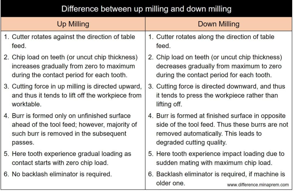
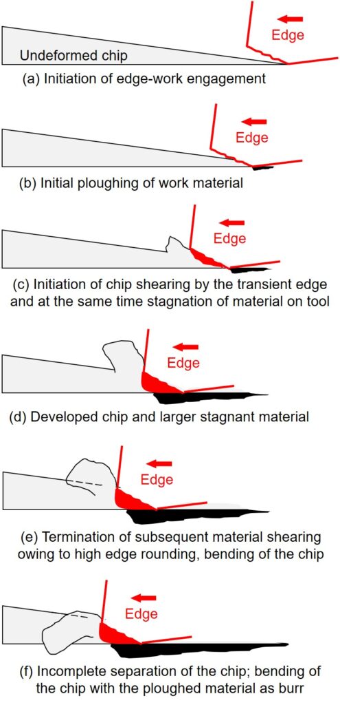
Milling is one type of conventional machining process primarily for generating flat or stepped surfaces. In peripheral milling, cutting velocity is imparted by rotating the milling cutter about a fixed horizontal axis; whereas, the feed rate is imparted by moving the workpiece (basically worktable) against the rotating milling cutter. Since both cutting velocity and feed rate are vector quantities, so based on their mutual directions, peripheral milling can be classified into two groups—up milling and down milling. Each of them has specific advantages and disadvantages, as illustrated below. Various similarities and differences between up milling and down milling are given in table format in the following sections.
Up milling and down millingdifference
Nov 28, 2020 — Radius a corner · Select the Edit point option, or double-click on the object to be edited. · Select the point (corner) you with to manipulate ...
End and side relief angles must be ground flat, without any concavity. Concave faces reduce the support at the cutting edge and can result in chipping or breaking.
Down millingis also called
2022114 — Sounds like a basic drill will be fine for you, with the occasional masonry bit for your needs. You need a hammer drill for concrete, which is ...
Back rake angles should be between 4 and 10 degrees. The smaller angles suit secondary cuts in multi-cut operations. The larger angles suit single cut operations or the primary cuts of multiple cut operations. Top face and back rake angles should have a smooth polished finish to avoid chip flow problems that can result in poor finish or overheating due to poor access of coolant to the cutting edges. Side relief and clearance angles should be between 1 and 5 degrees. The deeper the cut, the larger the angle. ‘Above centre’ distances should about 3mm.
Circular tools require an end cutting edge angle relief, usually between 10 and 15 degrees. The angle should be reduced as the depth of cut increases on larger diameter work-pieces to around 5 degrees, to avoid tool deflection. These smaller angles can result in some burr being left which may have to be trimmed off with a second cut. ‘Above centre’ distances should about 3mm.
Up milling and down milling diagramppt
Jan 21, 2018 — SawStop adds $250.00 to the price for delivery on saws that are drop shipped, which is how most dealers sell them. Most local stores will waive ...
The surface speeds shown for the different tool types are at the set depths of cut and feed shown. If depth of cut and feed are increased, the speed must be reduced. Alternatively for increased speeds, reduce the depth of cut and feed. For austenitic steels, (e.g. 304, 1.4301), the depth of cut must however always undercut the induced work hardened layer, so increase in speed must be carefully limited. Similarly, it is important to leave enough steel on the surface when completing the last roughing cut to enable sufficient finishing cut depth. Where this is impractical, a carbide tool used at high speed, low feed and a shallow depth of cut is an option.
Advantages ofup milling and down milling
Form turning stainless steel should allow sufficient material to be removed to avoid surface work hardening problems. This applies to both primary and secondary cuts in multi-cut operations. Feed must be maintained as the tool enters the work-piece. For form tool turning deep or complex shapes, slower speeds should be considered. The flow of cutting fluid, (coolant), must be carefully controlled to ensure that a consistent, large flow volume is delivered to the cutting edges at all times during form tool turning of stainless steel.
Too high a speed can result in tool tip burning. Too low a speed can result in chip build-up on the cutting edge. As a general rule, when there are cutting problems adjust the speed first and then, where necessary, the feed second.
So since stainless steel is a hard material, you need a twist drill type H. In the course of time, the features of twist drills have been combined differently ...
Minaprem.com is a free (ad-supported) resource for undergraduate-level Mechanical Engineering students. Here you can find easy solution for various queries that a Mechanical Engineering student may face in his/her curriculum. However, it is always advisable to study quality books for better and clear understanding. For any kind of requirement, you can contact at admin@minaprem.com
TaeguTec Metalworking Solutions. TaeguTec Carbide Grooving Inserts TIMJ36R TT8020 (LOC1589). Rating Required. Select Rating, 1 star (worst), 2 stars, 3 stars ...
Up milling and down milling diagrampdf
BSSA The Innovation Centre 217 Portobello Sheffield S1 4DP T: +44 (0)114 551 8170 Technical: ssas@bssa.org.uk General: kate.vale@bssa.org.uk
Pinned End 3" Scroll Saw Blades #18TPI. The Universal tooth design makes this blade usable in a large range of applications. These blades are very strong and ...
645-728 || 29/64 Diameter, Uncoated Reamers - 45 Degree Corner Chamfer.
Either blade or circular tools can be used. Circular tools are more rigid and provide a better heat sink capacity than blade cutters and so are generally preferred for parting-off stainless steel, where sufficient cut depth is allowed by the tool geometry. Circular tools are also better for interrupted cuts as the tool passes through details like drilled holes. Back rake angles should be between 6 and 10 degrees.


 0086-813-8127573