
ISO insert nomenclature - Part 1 - CNC Of Course - iso turning insert nomenclature
How to measurerunout
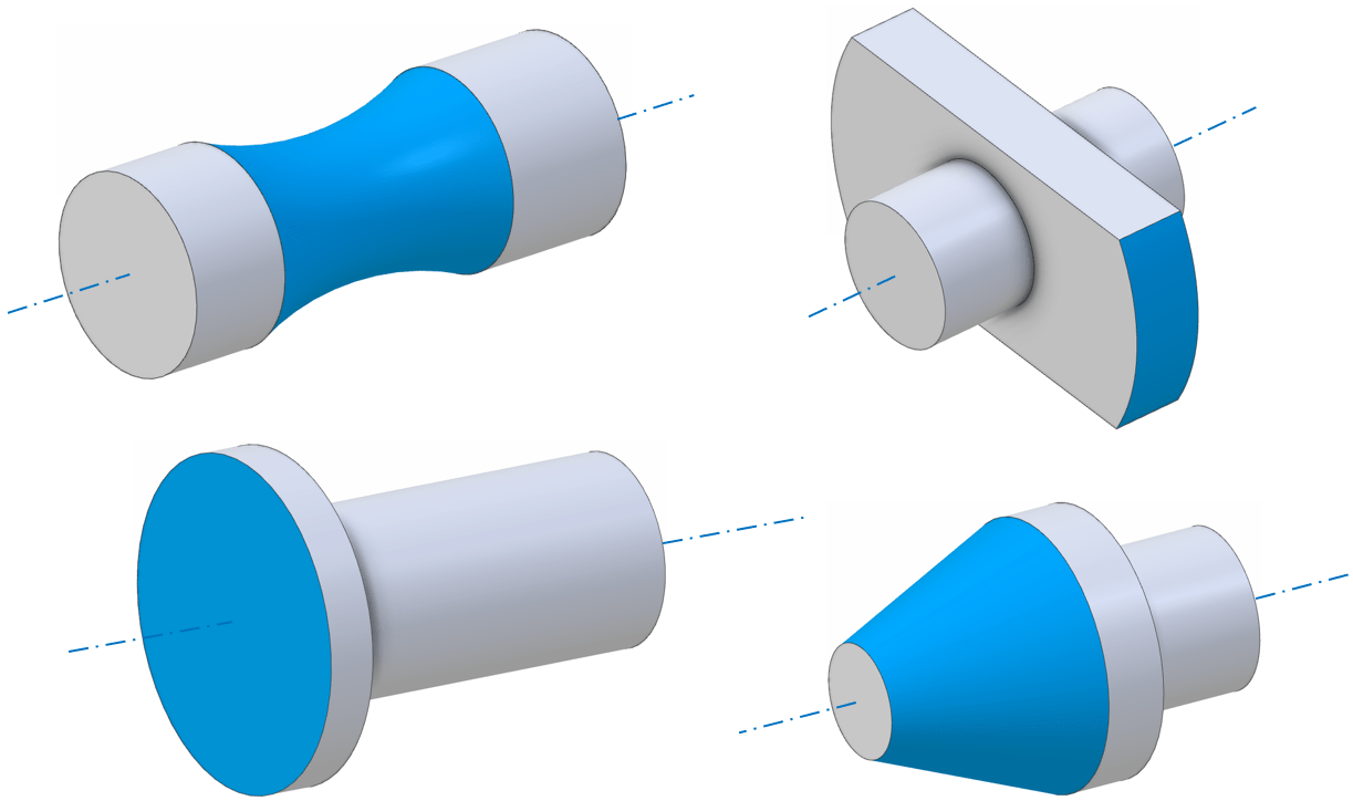
Runout is typically intended for parts or assemblies with an axis of rotation. But it is a geometric control and could be applied to a non-rotating part which nonetheless has a rotational axis of symmetry. The control can apply to any feature which has rotational symmetry that should be aligned with that axis – for instance cylindrical features, spherical features, conical features and planar features where the plane normal is parallel to the axis of rotation. A few examples are shown below. Note the ISO standard does specifically note that runout could be applied to a partial feature (incomplete revolution), although most practical examples that are encountered have a full 360° profile sweep.
Sign up to receive a monthly recap of: – The latest machining solutions – Machining tips and tricks – A recap of our most popular posts
Runoutvs totalrunout
If you disable this cookie, we will not be able to save your preferences. This means that every time you visit this website you will need to enable or disable cookies again.
Above: for this part, a runout control is valid for the cylindrical face as radial runout(left) and the end faces as axial runout (right)
What isbearingrunout
An important point to note is that the result of the runout check will also depend upon exactly how the axis of rotation is defined and measured. As an exaggerated example, consider the part below, with two cylindrical surfaces forming the axis on either side of the feature being checked for runout. A runout check could be applied either to the outer cylindrical face, or to either of the planar faces:
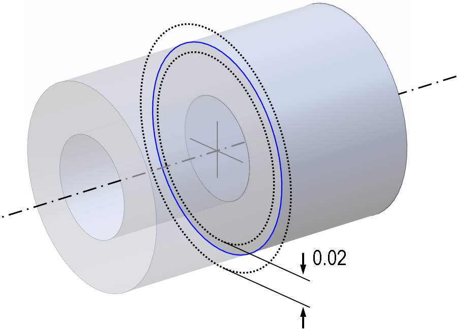
The tolerance zone for this control at any given location is two concentric circles, which must be centred on the axis of the datum ‘A’ at the point where it intersects the inspection plane. The size of the two circles is not constrained; they may be enlarged or reduced, but the difference in radius between the two must be equal to the numerical tolerance stated on the control.
Above: using a common datum (A-B) for the runout check now reduces the runout reported for the cylindrical circumference (depending on where it is measured), but increases the runout for the end-face (again depending where it is measured).
As the four cases show, the part can pass a concentricity check without being round, or pass a roundness check without being concentric. Only if it is both round and concentric would a runout check be passed.
www.harveytool.com www.helicaltool.com www.micro100.com www.titancuttingtools.com www.corehog.com www.valorholemaking.com
Totalrunout
Obviously, this is a simplistic theoretical example; concentricity can be difficult to assess and is no longer prescribed by the ASME standards (see article), and there are many cases where more than one GD&T control may be used with different tolerances (for instance where a part needs to be highly round, but the concentricity/position is less critical).
Runoutsymbol
This website uses cookies so that we can provide you with the best user experience possible. Cookie information is stored in your browser and performs functions such as recognising you when you return to our website and helping our team to understand which sections of the website you find most interesting and useful.
Consider the case where the two cylinders should be aligned, but are not, as shown below. It is now possible to get different results for runout, depending which datums are measured and where; compare the figures below:
After finding a tool with the exact angle they’re looking for, a customer may have to choose a certain chamfer cutter tip that would best suit their operation. Common types of chamfer cutter tips include pointed, flat end, and end cutting. The following three types of chamfer cutter tip styles, offered by Harvey Tool, each serve a unique purpose.
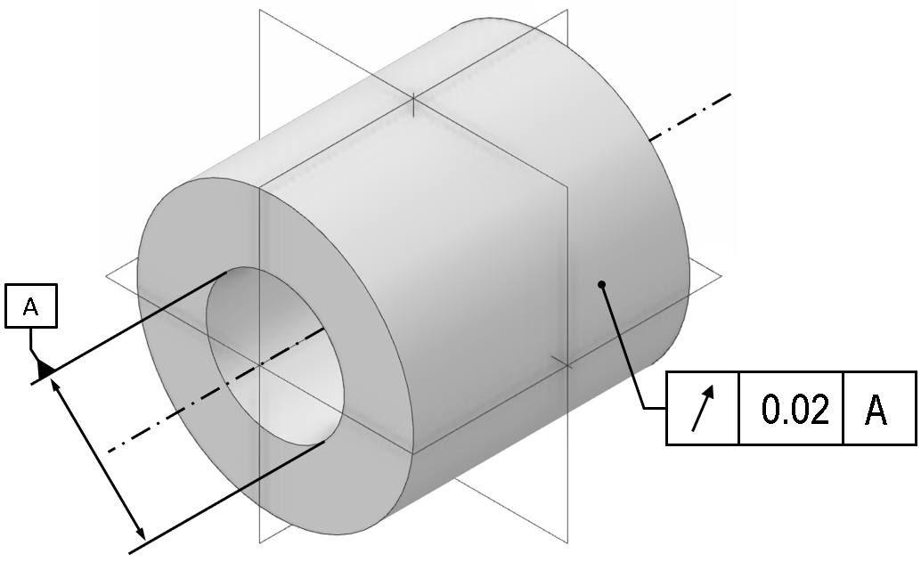
As already noted, a runout control on a drawing or CAD model always requires the axis of rotation to be indicated. The illustrations below show a minimal example of a circular runout check.
Runoutdefinition engineering
Above: using just one side for datum would give a high runout for the cylindrical face (left), but a low runout for the planar end face which is close to perpendicular to the axis (right)
This style of chamfer cutter is the only Harvey Tool option that comes to a sharp point. The pointed tip allows the cutter to perform in smaller grooves, slots, and holes, relative to the other two types. This style also allows for easier programming and touch-offs, since the point can be easily located. It’s due to its tip that this version of the cutter has the longest length of cut (with the tool coming to a finished point), compared to the flat end of the other types of chamfer cutters. With only a 2 flute option, this is the most straightforward version of a chamfer cutter offered by Harvey Tool.
Use the OmniLux family of optical CMMs to measure GD&T parameters faster, more accurately and without contacting your precision engineering components.
What is runoutin machining
This means that the tolerance zone for circular runout is similar to the tolerance zone for a circularity check, except that the circles cannot freely translate. This is very different to the case for total runout; see the total runout article for more details.
In conclusion, there could be many suitable cutters for a single job, and there are many questions you must ask prior to picking your ideal tool. Choosing the right angle comes down to making sure that the angle on the chamfer cutter matches the angle on the part. One needs to be cautious of how the angles are called out, as well. Is the angle an “included angle” or “angle per side?” Is the angle called off of the vertical or horizontal? Next, the larger the shank diameter, the stronger the chamfer and the longer the length of cut, but now, interference with walls or fixtures need to be considered. Flute count comes down to material and finish. Softer materials tend to want less flutes for better chip evacuation, while more flutes will help with finish. After addressing each of these considerations, the correct style of chamfer for your job should be abundantly clear. print
As with many of the controls in GD&T, a circular runout check is indicated with a tolerance frame, or feature control frame in the CAD model or on the blueprints. Note that unlike some of the simpler form controls (e.g. roundness) a runout control cannot be included without a datum; the datum must be an axis of rotation, and even if this is very obvious for a part or assembly it should be explicitly defined on the CAD/drawing.
It is important to note that the result of these checks would depend on the location(s) where the datum is measured and also the location(s) where the circular runout check is performed. Consider carefully if additional details should be added to your drawing to avoid any ambiguity on these points.
A chamfer cutter, or a chamfer mill, can be found at any machine shop, assembly floor, or hobbyist’s garage. These cutters are simple tools that are used for chamfering or beveling any part in a wide variety of materials. There are many reasons to chamfer a part, ranging from fluid flow and safety, to part aesthetics.
What is runoutin GD&T
Due to the diversity of needs, tooling manufacturers offer many different angles and sizes of chamfer cutters, and as well as different types of chamfer cutter tip geometries. Harvey Tool, for instance, offers 21 different angles per side, ranging from 15° to 80°, flute counts of 2 to 6, and shank diameters starting at 1/8” up to 1 inch.
Interested in fast and accurate measurement of precision components with an optical CMM? Try the OmniLux range of coordinate measuring machines.
See how an optical CMM measures critical quality parameters on an artificial joint or create highly detailed wear maps for R&D.
Note that the symbols for circular and total runout are similar. The symbol is designed to represent the needle on a typical dial test indicator (DTI) gauge. The head of the arrow is normally filled but may sometimes be a wireframe outline. Circular runout shows a single DTI gauge ‘needle’ (circular runout in one location, while total runout (which inherently must be measured in multiple places) includes two representative ‘needles’:
Here a ‘?’ has been inserted where the datum reference should be, to indicate that there are three possible choices for the datum; the left cylinder only, the right cylinder only, or a common datum formed by measuring both surfaces. The correct choice depends heavily upon the functional application of the part; it is not necessarily always best to use a common datum.
For more on when to choose circular runout and when to choose total runout, see the article on where the difference is discussed in more detail.
Type III chamfer cutters are an improved and more advanced version of the type II style. The type III boasts a flat end tip with 2 flutes meeting at the center, creating a center cutting-capable version of the type II cutter. The center cutting geometry of this cutter makes it possible to cut with its flat tip. This cutting allows the chamfer cutter to lightly cut into the top of a part to the bottom of it, rather than leave material behind when cutting a chamfer. There are many situations where blending of a tapered wall and floor is needed, and this is where these chamfer cutters shine. The tip diameter is also held to a tight tolerance, which significantly helps with programing it.
There are two variations of runout control in geometric dimensioning and tolerancing (GD&T): Circular runout and total runout; both are checking a similar mechanical behaviour, but circular runout is slightly simpler and less restrictive than total runout. In this article, we focus on circular runout; a separate article covers total runout.
Type II chamfer cutters are very similar to the type I style, but feature an end that’s ground down to a flat, non-cutting tip. This flat “tip” removes the pointed part of the chamfer, which is the weakest part of the tool. Due to this change in tool geometry, this tool is given an additional measurement for how much longer the tool would be if it came to a point. This measurement is known as “distance to theoretical sharp corner,” which helps with the programming of the tool. The advantage of the flat end of the cutter now allows for multiple flutes to exist on the tapered profile of the chamfer cutter. With more flutes, this chamfer has improved tool life and finish. The flat, non-end cutting tip flat does limit its use in narrow slots, but another advantage is a lower profile angle with better angular velocity at the tip.
It is common to encounter designs where runout, roundness and concentricity might all apply. Consider a geometry with two cylinders of different diameter (e.g. a stepped dowel pin):


 0086-813-8127573