
Lathe vs Milling Machine: What's the Difference? | Blog Posts - lathe milling machine
Tools, service and local support. Our FS Tool® & FS Cruing® distributors and application specialists span many countries with the same purpose, you just need to choose one and get started!
In the event of a disruption to services or facilities for customers with disabilities FS Tool Corporation will post a notice about the reason for disruption, its anticipated length of time, and a description of alternative services, if available.
Our brazed cutters for shapers, routers and CNC machines have been developed over the last three decades. With a wide variety of profiles and configurations, our specialty is in making what you need.
I had problems. They asked questions then came, educated and trained us, and solved everything. It's not about price, it's about service.
FS Tool Corporation is committed to excellence in providing goods and services to all customers including people with disabilities. We believe in inclusion, and we are committed to meeting the needs of people with disabilities in a timely manner.
FS Tool Corporation 71 Hobbs Gate Markham, Ontario, Canada L3R 9T9
The Transportation Standard sets out requirements to help transportation and public transit providers as well as municipalities, universities, colleges, hospitals and school boards make their transportation services and vehicles accessible to people with disabilities. This standard does not apply to FS Tool Corporation.
Organizations that provide goods or services to the public or to other businesses in Ontario have legal obligations under the standard. The standard is aimed at making customer service operations accessible to people with disabilities.
Of the thousands of tooling solutions we make, these product pages capture some of the most common standard items. For Composites, Metalworking, Plastics, and custom tooling solution, we're application driven. This means after a short chat we'll provide you with technical drawings and application directives relevant to your unique application.
CNC machines can exist in virtually any of the forms of manual machinery, like horizontal mills. The most advanced CNC milling-machines, the multiaxis machine, add two more axes in addition to the three normal axes (XYZ). Horizontal milling machines also have a C or Q axis, allowing the horizontally mounted workpiece to be rotated, essentially allowing asymmetric and eccentric turning. The fifth axis (B axis) controls the tilt of the tool itself. When all of these axes are used in conjunction with each other, extremely complicated geometries, even organic geometries such as a human head can be made with relative ease with these machines. But the skill to program such geometries is beyond that of most operators. Therefore, 5-axis milling machines are practically always programmed with CAM.
A horizontal mill has the same short but the cutters are mounted on a horizontal spindle, or arbor, mounted across the table. Many horizontal mills also feature a built-in rotary table that allows milling at various angles; this feature is called a universal table. While endmills and the other types of tools available to a vertical mill may be used in a horizontal mill, their real advantage lies in arbor-mounted cutters, called side and face mills, which have a cross section rather like a circular saw, but are generally wider and smaller in diameter. Because the cutters have good support from the arbor and have a larger cross-sectional area than an end mill, quite heavy cuts can be taken enabling rapid material removal rates. These are used to mill grooves and slots. Plain mills are used to shape flat surfaces. Several cutters may be ganged together on the arbor to mill a complex shape of slots and planes. Special cutters can also cut grooves, bevels, radii, or indeed any section desired. These specialty cutters tend to be expensive. Simplex mills have one spindle, and duplex mills have two. It is also easier to cut gears on a horizontal mill. Some horizontal milling machines are equipped with a power-take-off provision on the table. This allows the table feed to be synchronized to a rotary fixture, enabling the milling of spiral features such as hypoid gears.
Peter Baida,[26] citing Edward A. Battison's article "Eli Whitney and the Milling Machine," which was published in the Smithsonian Journal of History in 1966, exemplifies the dispelling of the "Great Man" image of Whitney by historians of technology working in the 1950s and 1960s. He quotes Battison as concluding that "There is no evidence that Whitney developed or used a true milling machine." Baida says, "The so-called Whitney machine of 1818 seems actually to have been made after Whitney's death in 1825." Baida cites Battison's suggestion that the first true milling machine was made not by Whitney, but by Robert Johnson of Middletown.[26]
In these early years, milling was often viewed as only a roughing operation to be followed by finishing with a hand file. The idea of reducing hand filing was more important than replacing it.
We are committed to ensuring equal access and participation for people with disabilities and to treating people with disabilities in a manner that respects their dignity and independence.
We will communicate with people with disabilities in ways that take into account their disability and respects their dignity and independence.
Carbidetooling
Around the end of World War I, machine tool control advanced in various ways that laid the groundwork for later CNC technology. The jig borer popularized the ideas of coordinate dimensioning (dimensioning of all locations on the part from a single reference point); working routinely in "tenths" (ten-thousandths of an inch, 0.0001") as an everyday machine capability; and using the control to go straight from drawing to part, circumventing jig-making. In 1920 the new tracer design of J.C. Shaw was applied to Keller tracer milling machines for die sinking via the three dimensional copying of a template. This made die sinking faster and easier just as dies were in higher demand than ever before, and was very helpful for large steel dies such as those used to stamp sheets in automobile manufacturing. Such machines translated the tracer movements to input for servos that worked the machine leadscrews or hydraulics. They also spurred the development of antibacklash leadscrew nuts. All of the above concepts were new in the 1920s but became routine in the NC/CNC era. By the 1930s, incredibly large and advanced milling machines existed, such as the Cincinnati Hydro-Tel, that presaged today's CNC mills in every respect except for CNC control itself.
We'd like to hear from you, and if you're in the area please stop by for coffee and a tour of our headquarters and production facilities.
Milling is a cutting process that uses a milling cutter to remove material from the surface of a workpiece. The milling cutter is a rotary cutting tool, often with multiple cutting points. As opposed to drilling, where the tool is advanced along its rotation axis, the cutter in milling is usually moved perpendicular to its axis so that cutting occurs on the circumference of the cutter. As the milling cutter enters the work piece, the cutting edges (flutes or teeth) of the tool repeatedly cut into and exit from the material, shaving off chips (swarf) from the work piece with each pass. The cutting action is shear deformation; material is pushed off the work piece in tiny clumps that hang together to a greater or lesser extent (depending on the material) to form chips. This makes metal cutting somewhat different (in its mechanics) from slicing softer materials with a blade.
Unique in the world, the inserts for the C∅NSTANT pre-milling system can be quickly and accurately changed in the field. The disposable inserts locate from our unique Ridgeline that is positioned under and behind the cutting edge, preventing debris from accumulating and causing erosion of the crtical surface.
Our teeth are larger with precision ground configurations, and our plates are polished then hammered and tensioned perfectly.
SK and HSK tooling, sometimes called "Hollow Shank Tooling", is much more common in Europe where it was invented than it is in the United States. It is claimed that HSK tooling is even better than BT Tooling at high speeds. The holding mechanism for HSK tooling is placed within the (hollow) body of the tool and, as spindle speed increases, it expands, gripping the tool more tightly with increasing spindle speed. There is no pull stud with this type of tooling.
A third type also exists, a lighter, more versatile machine, called a mill-drill. The mill-drill is a close relative of the vertical mill and quite popular in light industry; and with hobbyists. A mill-drill is similar in basic configuration to a very heavy drill press, but equipped with an X-Y table and a much larger column. They also typically use more powerful motors than a comparably sized drill press, most are muti-speed belt driven with some models having a geared head or electronic speed control. They generally have quite heavy-duty spindle bearings to deal with the lateral loading on the spindle that is created by a milling operation. A mill drill also typically raises and lowers the entire head, including motor, often on a dovetailed (sometimes round with rack and pinion) vertical column. A mill drill also has a large quill that is generally locked during milling operations and released to facilitate drilling functions. Other differences that separate a mill-drill from a drill press may be a fine tuning adjustment for the Z-axis, a more precise depth stop, the capability to lock the X, Y or Z axis, and often a system of tilting the head or the entire vertical column and powerhead assembly to allow angled cutting-drilling. Aside from size, the principal difference between these lighter machines and larger vertical mills is that the X-Y table is at a fixed elevation; the Z-axis is controlled by moving the head or quill down toward the X,Y table. A mill drill typically has an internal taper fitting in the quill to take a collet chuck, face mills, or a Jacobs chuck similar to the vertical mill.
FS Tool Corporation 210 South Eighth Street Lewiston, New York, USA 14092
In 1861, Frederick W. Howe, while working for the Providence Tool Company, asked Joseph R. Brown of Brown & Sharpe for a solution to the problem of milling spirals, such as the flutes of twist drills. These were usually filed by hand at the time.[30] (Helical planing existed but was by no means common.) Brown designed a "universal milling machine" that, starting from its first sale in March 1862, was wildly successful. It solved the problem of 3-axis travel (i.e., the axes that we now call XYZ) much more elegantly than had been done in the past, and it allowed for the milling of spirals using an indexing head fed in coordination with the table feed. The term "universal" was applied to it because it was ready for any kind of work, including toolroom work, and was not as limited in application as previous designs. (Howe had designed a "universal miller" in 1852, but Brown's of 1861 is the one considered a groundbreaking success.)[30]
During the 1950s, numerical control moved slowly from the laboratory into commercial service. For its first decade, it had rather limited impact outside of aerospace work. But during the 1960s and 1970s, NC evolved into CNC, data storage and input media evolved, computer processing power and memory capacity steadily increased, and NC and CNC machine tools gradually disseminated from an environment of huge corporations and mainly aerospace work to the level of medium-sized corporations and a wide variety of products. NC and CNC's drastic advancement of machine tool control deeply transformed the culture of manufacturing.[35] The details (which are beyond the scope of this article) have evolved immensely with every passing decade.
Carbide cutter manufacturersin canada
FS Tool Corporation will use reasonable efforts to ensure that its policies, practices and procedures are consistent with the following standard requirements:
We are unmatched in producing custom profiled inserts. Our technology, inspection, and precision grinding, lead North American and our application experience ensures your profiles perform seamlessly.
These products represent the wide range of our engineering and production capabilities. They also act as a foundation when addressing your application's unique requirements. While virtually every common tool design is available in our full-line catalogue, we often modify these items or transfer them into custom builds to maximize performance.
In 1783, Samuel Rehe invented a true milling machine.[20] In 1795, Eli Terry began using a milling machine at Plymouth Connecticut in the production of tall case clocks. With the use of his milling machine, Terry was the first to accomplish Interchangeable parts in the clock industry. Milling wooden parts was efficient in interchangeable parts, but inefficient in high yields. Milling wooden blanks results in a low yield of parts because the machines single blade would cause loss of gear teeth when the cutter hit parallel grains in the wood. Terry later invented a spindle cutting machine to mass produce parts in 1807. Other Connecticut clockmakers like James Harrison of Waterbury, Thomas Barnes of Litchfield, and Gideon Roberts of Bristol, also used milling machines to produce their clocks.[21]
The cutting surfaces of a milling cutter are generally made of a hard and temperature-resistant material, so that they wear slowly. A low cost cutter may have surfaces made of high speed steel. More expensive but slower-wearing materials include cemented carbide. Thin film coatings may be applied to decrease friction or further increase hardness.
An improvement on CAT Tooling is Bridgeport Taper (BT) Tooling, which looks similar and can easily be confused with CAT tooling. Like CAT Tooling, BT Tooling comes in a range of sizes and uses the same NMTB body taper. However, BT tooling is symmetrical about the spindle axis, which CAT tooling is not. This gives BT tooling greater stability and balance at high speeds. One other subtle difference between these two toolholders is the thread used to hold the pull stud. CAT Tooling is all Imperial thread and BT Tooling is all Metric thread. Note that this affects the pull stud only; it does not affect the tool that they can hold. Both types of tooling are sold to accept both Imperial and metric sized tools.
Carbide cutter manufacturersin usa
Three flute, small diameter compression spirals/end-mills that provide excellent tool life and edge finishes in difficult materials.
Brown also developed and patented (1864) the design of formed milling cutters in which successive sharpenings of the teeth do not disturb the geometry of the form.[19]
Mill orientation is the primary classification for milling machines. The two basic configurations are vertical and horizontal – referring to the orientation of the rotating spindle upon which the cutter is mounted. However, there are alternative classifications according to method of control, size, purpose and power source.
Our 496 page Full-line catalogue features a wide range of cutting tools for cutting wood, composites, plastics and non-ferrous metals.
The Integrated Accessibility Standards Regulation establishes accessibility standards and introduces requirements for Information and Communications, Employment, Transportation and the Design of Public Spaces. Organizations are required to develop, implement and maintain policies governing how the organization will achieve accessibility through meeting its requirements under the standard, and establish, implement, document and post a multi-year accessibility plan.
Since the 1960s there has developed an overlap of usage between the terms milling machine and machining center. NC/CNC machining centers evolved from milling machines, which is why the terminology evolved gradually with considerable overlap that still persists. The distinction, when one is made, is that a machining center is a mill with features that pre-CNC mills never had, especially an automatic tool changer (ATC) that includes a tool magazine (carousel), and sometimes an automatic pallet changer (APC). In typical usage, all machining centers are mills, but not all mills are machining centers; only mills with ATCs are machining centers.
In this approach, the required pocket boundary is used to derive the tool path. In this case, the cutter is always in contact with the work material. Hence the idle time spent in positioning and retracting the tool is avoided. For large-scale material removal, contour-parallel tool path is widely used because it can be consistently used with up-cut or down-cut method during the entire process. There are three different approaches that fall into the category of contour-parallel tool path generation. They are:
The integration of milling into turning environments, and vice versa, began with live tooling for lathes and the occasional use of mills for turning operations. This led to a new class of machine tools, multitasking machines (MTMs), which are purpose-built to facilitate milling and turning within the same work envelope.
As material passes through the cutting area of a milling machine, the blades of the cutter take swarfs of material at regular intervals. Surfaces cut by the side of the cutter (as in peripheral milling) therefore always contain regular ridges. The distance between ridges and the height of the ridges depend on the feed rate, number of cutting surfaces, the cutter diameter.[4] With a narrow cutter and rapid feed rate, these revolution ridges can be significant variations in the surface finish.
Pocket milling has been regarded as one of the most widely used operations in machining. It is extensively used in aerospace and shipyard industries. In pocket milling the material inside an arbitrarily closed boundary on a flat surface of a work piece is removed to a fixed depth. Generally flat bottom end mills are used for pocket milling. Firstly roughing operation is done to remove the bulk of material and then the pocket is finished by a finish end mill.[10] Most of the industrial milling operations can be taken care of by 2.5 axis CNC milling.[11] This type of path control can machine up to 80% of all mechanical parts. Since the importance of pocket milling is very relevant, therefore effective pocketing approaches can result in reduction in machining time and cost.[12] NC pocket milling can be carried out mainly by two tool paths, viz., linear and non-linear.[13]
Milling is the process of machining using rotary cutters to remove material[1] by advancing a cutter into a workpiece. This may be done by varying directions[2] on one or several axes, cutter head speed, and pressure.[3] Milling covers a wide variety of different operations and machines, on scales from small individual parts to large, heavy-duty gang milling operations. It is one of the most commonly used processes for machining custom parts to precise tolerances.
We produce a wide range of common Moulder, Planer and other cutters with straight and custom profiled knives. These are all available with open bores, or mounted on arbors with spindle connection types such as HSK, ISO or BT.
Industrial quality precision Through-hole, Brad point/Dowel, and Boring/Hinge drill bits are the backbone of assembly. Listed are the most common sizes, and styles, with many more inventoried.
A person with a disability who is accompanied by a support person shall be allowed to have that person accompany them at all times while on our premises.
National and international standards are used to standardize the definitions, environmental requirements, and test methods used for milling. Selection of the standard to be used is an agreement between the supplier and the user and has some significance in the design of the mill. In the United States, ASME has developed the standards B5.45-1972 Milling Machines and B94.19-1997 Milling Cutters and End Mills.
We specialize in Non-Ferrous metals such as Aluminium, Magnesium and green alloys with PCD and Carbide cutting tools for each unique application.
Milling machines evolved from the practice of rotary filing—that is, running a circular cutter with file-like teeth in the headstock of a lathe. Rotary filing and, later, true milling were developed to reduce time and effort spent hand-filing. The full story of milling machine development may never be known, because much early development took place in individual shops where few records were kept for posterity. However, the broad outlines are known, as summarized below. From a history-of-technology viewpoint, it is clear that the naming of this new type of machining with the term "milling" was an extension from that word's earlier senses of processing materials by abrading them in some way (cutting, grinding, crushing, etc.). Rotary filing long predated milling. A rotary file by Jacques de Vaucanson, circa 1760, is well known.[18][19]
Carbidecutting Tools for Lathe
We ship our tools across 4 states and into a different country to have FS sharpen our tools. It's hard to explain just how good they are.
The accessories and cutting tools used on machine tools (including milling machines) are referred to in aggregate by the mass noun "tooling". There is a high degree of standardization of the tooling used with CNC milling machines, and a lesser degree with manual milling machines. To ease up the organization of the tooling in CNC production many companies use a tool management solution.
In zig milling, the tool moves only in one direction. The tool has to be lifted and retracted after each cut, due to which machining time increases. However, in case of zig milling surface quality is better.
Engineered with perfectly tensioned, polished plates with oversized carbide teeth that are precision ground with complex geometries for specific applications.
In 1952, numerical control reached the developmental stage of laboratory reality. The first NC machine tool was a Cincinnati Hydrotel milling machine retrofitted with a scratch-built NC control unit. It was reported in Scientific American,[34] just as another groundbreaking milling machine, the Brown & Sharpe universal, had been in 1862.
FS Tool Corporation is committed to working towards full compliance with all applicable standards under the Accessibility for Ontarians with Disabilities Act, 2005 (AODA).
For manual milling machines, there is less standardization, because a greater plurality of formerly competing standards exist. Newer and larger manual machines usually use NMTB tooling. This tooling is somewhat similar to CAT tooling but requires a drawbar within the milling machine. Furthermore, there are a number of variations with NMTB tooling that make interchangeability troublesome. The older a machine, the greater the plurality of standards that may apply (e.g., Morse, Jarno, Brown & Sharpe, Van Norman, and other less common builder-specific tapers). However, two standards that have seen especially wide usage are the Morse #2 and the R8, whose prevalence was driven by the popularity of the mills built by Bridgeport Machines of Bridgeport, Connecticut. These mills so dominated the market for such a long time that "Bridgeport" is virtually synonymous with "manual milling machine". Most of the machines that Bridgeport made between 1938 and 1965 used a Morse taper #2, and from about 1965 onward most used an R8 taper.
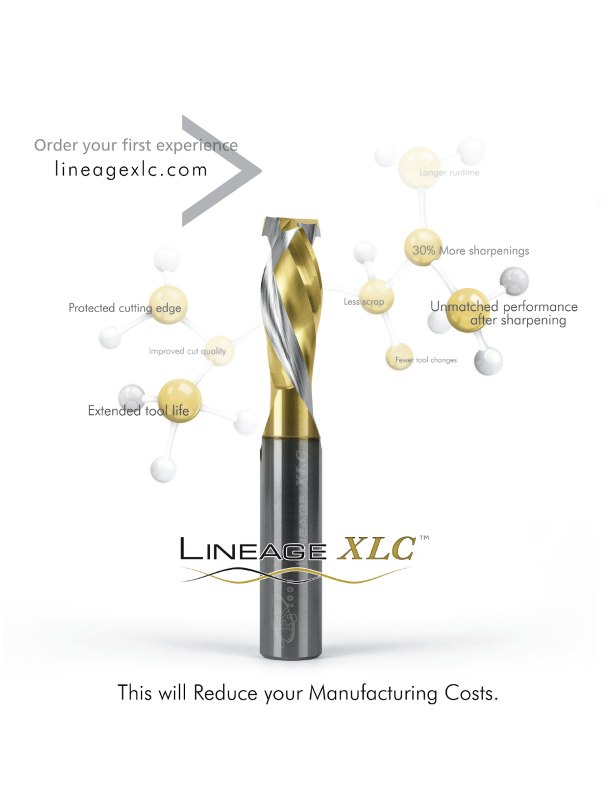
In addition to providing greater than 40% longer life and 30% more sharpenings, the truly unique nature of XLC is that it performs better after the first sharpening.
Balancing, tensioning, and seating, all play a role in the performance cutting tool. When we take in a cutting tool for service, we understand your expectation is to receive back something better. Sharpening alone will not produce the performance you need, the act of cutting is the combination of many forces that begin where the tool connects to your machine. Tools fully serviced by FS Tool® & FS Cruing® receive a cleaning, sharpening and inspection to ensure what you get back carries the same commitment found in our new tools.
These common insert cutters and profiles are the foundation of our insert tooling product line. We have thousands of custom profiles developed from each stile, rail, and cutter design. With decades of custom tooling designs, we can quickly bring your custom profile to form and your customer's dreams to reality.
FS Tool Corporation will use reasonable efforts to ensure that its policies, practices and procedures are consistent with the following standard requirements: Goods or services are provided in a manner that respects the dignity and independence of persons with disabilities. The provision of goods or services to persons with disabilities is integrated, unless an alternate measure is necessary, to enable a person with a disability to obtain, use or benefit from the goods or services. Persons with disabilities are given an opportunity equal to that given to others to obtain, use and benefit from the goods or services. Persons with disabilities may use assistive devices and/or support persons in access of the goods and services. Persons with disabilities and their service animals are accommodated in all aspects of service provision unless the animal is otherwise excluded by law. FS Tool employees, when communicating with a person with a disability, will do so in a manner that takes into account the person’s disability. The following measures have been implemented by FS Tool Corporation. Senior Management has established and reviewed appropriate policies, practices and procedures as required. The Accessible Customer Service Policy is published on our website. When a service disruption occurs, notice will be provided on the website, over the phone, or in writing where applicable. A process has been established to ensure that all feedback received is reviewed and analyzed to identify potential gaps in customer services and appropriate actions are taken. Training is provided on AODA Customer Service to any person who deals with the public on behalf of FS Tool. Employees have been trained that any person with a disability who is accompanied by a support person or service animal will be allowed to enter public spaces of FS Tool’s premises with his or her support person or service animal. At no time will a person with a disability who is accompanied by a support person or service animal be prevented from having access to his or her support person and/or service animal while on our premises. Guidelines on providing service to customers with disabilities has been posted on the Public Drive. The Customer Service Policy will be reviewed annually and updated as necessary. The following measures are planned between now and 2021: All customer service policies, practices and procedures will be reviewed annually to ensure ongoing compliance with accessibility requirements. The Accessible Customer Service Policy published on our website shall be made available in accessible formats, when requested. All customer feedback received shall be reviewed quarterly to identify potential gaps in customer services. Training will be provided on AODA Customer Service to any new employee who deals with the public on behalf of FS Tool during their orientation. All customer access public spaces will be designed and/or modified with accessibility needs in mind. Integrated Accessibility Standard The Integrated Accessibility Standards Regulation establishes accessibility standards and introduces requirements for Information and Communications, Employment, Transportation and the Design of Public Spaces. Organizations are required to develop, implement and maintain policies governing how the organization will achieve accessibility through meeting its requirements under the standard, and establish, implement, document and post a multi-year accessibility plan. Information and Communications FS Tool Corporation will use reasonable efforts to ensure that its policies, practices and procedures are consistent with the following standard requirements: Processes for receiving and responding to feedback are accessible to persons with disabilities by providing or arranging for accessible formats and communications support, upon request. Provide or arrange for the provision of accessible formats and communications support for persons with disabilities in a timely manner that takes into account the person’s accessibility needs due to disability and is at a cost that is no more than the regular cost charged to other persons. Consult with the person making the request in determining the suitability of an accessible format or communication support. Notify the public about the availability of accessible formats and communication supports. Make our internet websites and web content conform to the World Wide Web Consortium Web Content Accessibility Guidelines (WCAG) 2.0, Level AA, by January 1, 2021. The following measures have been implemented by FS Tool Corporation. Feedback processes have been reviewed to ensure the processes are accessible to persons with disabilities by providing or arranging for accessible formats and communications supports, upon request. Marketing and IT departments have reviewed accessible formats and communication support technology is currently available in-house. Emergency procedures, plans or public safety information, that is publicly available, shall be provided in an accessible format or with appropriate communication supports upon request as soon as practicable. The following measures are planned between now and 2021: Continue to assess accessibility of existing website organization and content. Consult with persons requesting alternative formats. Commit to conform our website and web content to the World Wide Web Consortium Web Content Accessibility Guidelines (WCAG) 2.0, Level AA by January 1, 2021. Marketing and IT departments shall review accessible formats and communication support technology annually to ensure appropriate communication supports are available. Establish sources for accessible formatting that is not feasible to do in-house. Provide all new and/or changes to emergency procedures, plans, or public safety information in an accessible format or with appropriate communication supports upon request as soon as practicable. Employment Standard FS Tool Corporation will use reasonable efforts to ensure that its policies, practices and procedures are consistent with the following standard requirements: Notify employees and the public about the availability of accommodation for applicants with disabilities in the recruitment process. Notify job applicants that accommodations are available upon request in relation to the recruitment, assessment, selection and employment offer processes. Provide information to employees on policies to support employees with disabilities including the provision of job accommodations that take into account an employee’s accessibility needs due to disability. Consult with the employee when they request accessible formats and/or communication support to determine the suitability for providing information that is needed in order to perform the employee’s job or that is generally available to employees in the workplace. Provide individualized workplace emergency response information to employees who have a disability and need accommodation due to their disability. Have a written process for the development of documented individual accommodation plans for employees with disabilities and for employees who have been absent from work due to a disability and require disability-related accommodations in order to return to work. Performance management, advancement and career development processes shall take into account the accessibility needs of employees with disabilities as well as individual accommodation plans. The following measures have been implemented by FS Tool Corporation. The job posting process has been reviewed and language is incorporated on all internal and external job postings that accommodation is available in accordance with AODA. Language is incorporated in all notifications to applicants for interview that accommodation in accordance with AODA is available upon request. The recruitment process has been reviewed (tests, interview locations, etc.) to ensure barriers are removed or accessible formats are provided upon request. Offer letters of employment shall include a statement supporting FS Tool’s accessibility policies for accommodating employees with disabilities. Accessibility policies are posted on the public drive and are incorporated in the onboarding process for new employees. Ergonomic assessments of each department shall take place on an ongoing basis to identify barriers and implement improvements. Managers have been educated on the availability of accessible formats and communication supports. Current accommodation processes and practices have been reviewed. A standard process has been established for the development of individualized accommodation plans. A process has been established to consult with employees with a disability to determine the need for accommodation due to their disability and to provide Individualized Workplace Emergency Response Information where needed. The process for creating Individualized Workplace Emergency Response Information includes a provision for obtaining the employee’s consent to provide the information with those designated to provide assistance in the event of an emergency. The process for creating Individualized Workplace Emergency Response Information includes guidelines for when the plans and information are to be reviewed. A written return to work process has been developed for employees who have been absent from work due to a disability and require disability-related accommodations in order to return to work. Current performance review processes have been reviewed. Training and professional development materials have been reviewed to determine accessibility features. Redeployment efforts have been reviewed to ensure accommodation plans are taken into account. The following measures are planned between now and 2021: Language, tests and interview locations incorporated in the recruitment and selection process shall be reviewed annually to ensure compliance with AODA. Training in FS Tool’s accessibility policies and the requirements of Ontario’s accessibility laws and Ontario Human Rights Code as it applies to people with disabilities will be incorporated in the onboarding process for new employees. Ergonomic assessments of each department shall take place annually to identify barriers and implement improvements. Current accommodation processes and practices shall be reviewed annually. Existing individualized accommodation plans and return to work plans shall be reviewed as per the individual plan schedule. Transportation Standard The Transportation Standard sets out requirements to help transportation and public transit providers as well as municipalities, universities, colleges, hospitals and school boards make their transportation services and vehicles accessible to people with disabilities. This standard does not apply to FS Tool Corporation. Public Spaces Standard The Design of Public Spaces Standard makes it easier for people with disabilities to move through and use the environment. The requirements of the standard are divided into seven sections: Recreational trails and beach access routes. Outdoor public use eating areas, like those found at rest stops or picnic grounds. Outdoor play spaces. Exterior paths of travel (sidewalks or walkways) and their associated elements, such as ramps, stairs, curb ramps, rest areas and accessible pedestrian signals. Accessible off-street and on-street parking spaces. Obtaining services (service counters, fixed queuing guides and waiting areas). Maintenance planning. The standard requires organizations to incorporate accessibility when building new public spaces or making planned significant alterations to existing public spaces. The following measures are planned between now and 2021: Consider accessibility and establish plans to meet the standard whenever building or modifying of public spaces under FS Tool’s control. Take appropriate measures to prevent service disruptions to accessible parts of our public spaces, such as the access to owned offices and facilities. In the event of a service disruption, notify the public of the service disruption and alternatives available.
This Multi-Year Accessibility Plan outlines the policies, actions and plans that FS Tool Corporation has committed to put in place to improve accessibility and opportunities for people with disabilities. The current plan covers a five-year period 2017 – 2021.
Computers and CNC machine tools continue to develop rapidly. The personal computer revolution has a great impact on this development. By the late 1980s small machine shops had desktop computers and CNC machine tools. Soon after, hobbyists, artists, and designers began obtaining CNC mills and lathes. Manufacturers have started producing economically priced CNCs machines small enough to sit on a desktop which can cut at high resolution materials softer than stainless steel. They can be used to make anything from jewelry to printed circuit boards to gun parts, even fine art.
We offer a variety of common and custom bushings, flanges, spacers, and sleeves to ensure our tools work as we engineered them to.
Milling is performed with a milling cutter in various forms, held in a collet or similar which, in turn, is held in the spindle of a milling machine.
A universal milling machine is one with the facility to either have a horizontal spindle or a vertical spindle. The latter sometimes being on a two-axis turret enabling the spindle to be pointed in any direction on desires. The two options may be driven independently or from one motor through gearing. In either case, as the work is generally placed in the same place for either type of operation, the mechanism for the method not being used is moved out of the way. In smaller machines, "spares" may be lifted off while larger machines offer a system to retract those parts not in use.
Some of us love saw blades, others are crazy about insert tooling, or MDF doors, or Routing and nesting. It's this passionate, application and product based focus that makes us so effective at solving your challenges.
Gang milling refers to the use of two or more milling cutters mounted on the same arbor (that is, ganged) in a horizontal-milling setup. All of the cutters may perform the same type of operation, or each cutter may perform a different type of operation. For example, if several workpieces need a slot, a flat surface, and an angular groove, a good method to cut these (within a non-CNC context) would be gang milling. All the completed workpieces would be the same, and milling time per piece would be minimized.[5]
Service animals are allowed on the parts of our premises that are open to the public. If a person with a disability is accompanied by a guide dog or other service animal they are permitted to enter the premises with the animal and keep that animal with him or her.
General tolerances include: +/-0.005" (~0.1mm) for local tolerances across most geometries, +/-0.010" (~0.25mm) for plastics with variation depending on the size of the part, 0.030" (~0.75mm) minimum wall thickness for metals, and 0.060" (~1.5mm) minimum wall thickness for plastics.[36]
SpeedMaster, NestMax, and Aerotech are just some of our industry leading techologies and performance leading solutions. Our catalogue is a cross-section of our capabilities and a snapshot of our ever growing array of inventoried configurations for wood, plastics and composite applications.
Milling can be done with a wide range of machine tools. The original class of machine tools for milling was the milling machine (often called a mill). After the advent of computer numerical control (CNC) in the 1960s, milling machines evolved into machining centers: milling machines augmented by automatic tool changers, tool magazines or carousels, CNC capability, coolant systems, and enclosures. Milling centers are generally classified as vertical machining centers (VMCs) or horizontal machining centers (HMCs).
CNC milling machines nearly always use SK (or ISO), CAT, BT or HSK tooling. SK tooling is the most common in Europe, while CAT tooling, sometimes called V-Flange Tooling, is the oldest and probably most common type in the USA. CAT tooling was invented by Caterpillar Inc. of Peoria, Illinois, in order to standardize the tooling used on their machinery. CAT tooling comes in a range of sizes designated as CAT-30, CAT-40, CAT-50, etc. The number refers to the Association for Manufacturing Technology (formerly the National Machine Tool Builders Association (NMTB)) taper size of the tool.
With your craftsmanship dependent on your tooling, our selection of thousands of in-stock profile configurations can bring your shapes to life. A true industrial product, our industry leading carbide and brazing gives you dependable, long lasting performance that is repeatable after sharpening.
For more information about FS Tool Corporation’s AODA standards please click here to see our AODA Multi-Year Accessibility Plan.
DE-BOER Tool

The choice between vertical and horizontal spindle orientation in milling machine design usually hinges on the shape and size of a workpiece and the number of sides of the workpiece that require machining. Work in which the spindle's axial movement is normal to one plane, with an endmill as the cutter, lends itself to a vertical mill, where the operator can stand before the machine and have easy access to the cutting action by looking down upon it. Thus vertical mills are most favored for diesinking work (machining a mould into a block of metal).[6] Heavier and longer workpieces lend themselves to placement on the table of a horizontal mill.
Questions about stile and rail on your shaper or CNC?Click to ask us a question.We're here to earn your business with value-added support.
In 1936, Rudolph Bannow (1897–1962) conceived of a major improvement to the milling machine.[33] His company commenced manufacturing a new knee-and-column vertical mill in 1938. This was the Bridgeport milling machine, often called a ram-type or turret-type mill because its head has sliding-ram and rotating-turret mounting. The machine became so popular that many other manufacturers created copies and variants. Furthermore, its name came to connote any such variant. The Bridgeport offered enduring advantages over previous models. It was small enough, light enough, and affordable enough to be a practical acquisition for even the smallest machine shop businesses, yet it was also smartly designed, versatile, well-built, and rigid. Its various directions of sliding and pivoting movement allowed the head to approach the work from any angle. The Bridgeport's design became the dominant form for manual milling machines used by several generations of small- and medium-enterprise machinists. By the 1980s an estimated quarter-million Bridgeport milling machines had been built,[33] and they (and their clones) are still being produced today.
Most CNC milling machines (also called machining centers) are computer controlled vertical mills with the ability to move the spindle vertically along the Z-axis. This extra degree of freedom permits their use in diesinking, engraving applications, and 2.5D surfaces such as relief sculptures. When combined with the use of conical tools or a ball nose cutter, it also significantly improves milling precision without impacting speed, providing a cost-efficient alternative to most flat-surface hand-engraving work.
We will ensure that our staff is familiar with various assistive devices that may be used by customers with disabilities while accessing our goods and services.
Bestcarbide cutter manufacturers
During this era there was a continued blind spot in milling machine design, as various designers failed to develop a truly simple and effective means of providing slide travel in all three of the archetypal milling axes (X, Y, and Z—or as they were known in the past, longitudinal, traverse, and vertical). Vertical positioning ideas were either absent or underdeveloped. The Lincoln miller's spindle could be raised and lowered, but the original idea behind its positioning was to be set up in position and then run, as opposed to being moved frequently while running. Like a turret lathe, it was a repetitive-production machine, with each skilled setup followed by extensive fairly low skill operation.
In this approach, tool movement is multi-directional. One example of non-linear tool path is contour-parallel tool path.
The milling process removes material by performing many separate, small cuts. This is accomplished by using a cutter with many teeth, spinning the cutter at high speed, or advancing the material through the cutter slowly; most often it is some combination of these three approaches.[2] The speeds and feeds used are varied to suit a combination of variables. The speed at which the piece advances through the cutter is called feed rate, or just feed; it is most often measured as distance per time (inches per minute [in/min or ipm] or millimeters per minute [mm/min]), although distance per revolution or per cutter tooth are also sometimes used.
Dust Free Nesting. We invented the technology that changed nesting environment worldwide. With 98.4% dust extraction, Aerotech's safety and performance are unmatched.
This website uses cookies to improve your user experience. If you continue on this website, you will be providing your consent to our use of cookies.
Questions about cutting exruded components, or milling blocks?Click to ask us a question.We're here to earn your business with value-added support.
Employees who deal with the public receive training on the Accessibility for Ontarians with Disabilities Act, 2005, the requirements of the customer service standard and how to interact and communicate with people with various types of disabilities.
FS Tool Corporation will use reasonable efforts to ensure that its policies, practices and procedures are consistent with the following standard requirements:
There are cutting tools typically used in milling machines or machining centers to perform milling operations (and occasionally in other machine tools). They remove material by their movement within the machine (e.g., a ball nose mill) or directly from the cutter's shape (e.g., a form tool such as a hobbing cutter).
Disposable PCD insert pre-milling cutter systems that are capable of quickly and accurately replacing worn edges without ever programming an offer.
In the vertical milling machine the spindle axis is vertically oriented. Milling cutters are held in the spindle and rotate on its axis. The spindle can generally be lowered (or the table can be raised, giving the same relative effect of bringing the cutter closer or deeper into the work), allowing plunge cuts and drilling. The depth to which blades cut into the work can be controlled with a micrometer adjustment nut. There are two subcategories of vertical mills: the bed mill and the turret mill.
Our super high polish O-Flutes are unmatched, both in quality of cut and longevity for Acrylic, Aluminum and other plastics.
By 1940, automation via cams, such as in screw machines and automatic chuckers, had already been very well developed for decades. Beginning in the 1930s, ideas involving servomechanisms had been in the air, but it was especially during and immediately after World War II that they began to germinate (see also Numerical control > History). These were soon combined with the emerging technology of digital computers. This technological development milieu, spanning from the immediate pre–World War II period into the 1950s, was powered by the military capital expenditures that pursued contemporary advancements in the directing of gun and rocket artillery and in missile guidance—other applications in which humans wished to control the kinematics/dynamics of large machines quickly, precisely, and automatically. Sufficient R&D spending probably would not have happened within the machine tool industry alone; but it was for the latter applications that the will and ability to spend was available. Once the development was underway, it was eagerly applied to machine tool control in one of the many post-WWII instances of technology transfer.
We developed the XLC coating for laminate and high wear applications that require a sharp cutting edge. Lineage XLC technology works by localizing the wear to the face of the cutting edge only. By doing so, the worn edge maintains a sharper point and produces less heat. This in turn requires less force to cut, providing a better finish.
Smooth, single pass visible edges with less cutting pressure and longer run-times on all plywoods. The cherry on top is that we've coated them with Lineage XLC.
Gang milling was especially important before the CNC era, because for duplicate part production, it was a substantial efficiency improvement over manual-milling one feature at an operation, then changing machines (or changing setup of the same machine) to cut the next op. Today, CNC mills with automatic tool change and 4- or 5-axis control obviate gang-milling practice to a large extent.
The Design of Public Spaces Standard makes it easier for people with disabilities to move through and use the environment. The requirements of the standard are divided into seven sections:
We are known for optimizing the machining processes of CFRP, Honeycombs, Fibreglass, Kevlar, Phenolic, and other composites with application specific cutting tool designs and programming.
James Nasmyth built a milling machine very advanced for its time between 1829 and 1831.[28] It was tooled to mill the six sides of a hex nut that was mounted in a six-way indexing fixture.
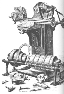
A milling machine built and used in the shop of Gay & Silver (aka Gay, Silver, & Co) in the 1830s was influential because it employed a better method of vertical positioning than earlier machines. For example, Whitney's machine (the one that Roe considered the very first) and others did not make provision for vertical travel of the knee. Evidently, the workflow assumption behind this was that the machine would be set up with shims, vise, etc. for a certain part design, and successive parts did not require vertical adjustment (or at most would need only shimming). This indicates that early thinking about milling machines was as production and not as toolroom machines.
In zig-zag milling, material is removed both in forward and backward paths. In this case, cutting is done both with and against the rotation of the spindle. This reduces the machining time but increases machine chatter and tool wear.
They're like family. We don't give our tooling or sharpening a second thought. They keep us ahead of the curve with the best tools.
A milling machine is often called a mill by machinists. The archaic term miller was commonly used in the 19th and early 20th centuries.[7]
Various other codes are also used. A CNC machine is operated by a single operator called a programmer. This machine is capable of performing various operations automatically and economically.
It is clear that milling machines as a distinct class of machine tool (separate from lathes running rotary files) first appeared between 1814 and 1818. The centers of earliest development of true milling machines were two federal armories of the U.S. (Springfield and Harpers Ferry) together with the various private armories and inside contractors that shared turnover of skilled workmen with them. Between 1912 and 1916, Joseph W. Roe, a respected founding father of machine tool historians, credited Eli Whitney (one of the private arms makers mentioned above) with producing the first true milling machine.[22][23] By 1918, he considered it "Probably the first milling machine ever built—certainly the oldest now in existence […]."[24] However, subsequent scholars, including Robert S. Woodbury[25] and others,[26] have improved upon Roe's early version of the history and suggest that just as much credit—in fact, probably more—belongs to various other inventors, including Robert Johnson of Middletown, Connecticut; Captain John H. Hall of the Harpers Ferry armory; Simeon North of the Staddle Hill factory in Middletown; Roswell Lee of the Springfield armory; and Thomas Blanchard. (Several of the men mentioned above are sometimes described on the internet as "the inventor of the first milling machine" or "the inventor of interchangeable parts". Such claims are oversimplified, as these technologies evolved over time among many people.)
We are relentless in our support of your operation with innovative cutting solutions and application support. That is why for 47 years we have partnered with our customers and ensured our solutions evolved with their materials and machining approaches.Our products are cutting tools and we take them very seriously.
In person or in writing: FS Tool Corporation 71 Hobbs Gate Markham, Ontario L3R 9T9 Attention: Human Resources Department
The standard requires organizations to incorporate accessibility when building new public spaces or making planned significant alterations to existing public spaces.
To facilitate this commitment, we will establish, maintain and document a multi-year accessibility plan that will be reviewed and updated every year to identify progress made in addressing barriers and it will be posted on our website.
Cutting tool companies
In this approach, the tool travels along a gradually evolving spiral path. The spiral starts at the center of the pocket to be machined and the tool gradually moves towards the pocket boundary. The direction of the tool path changes progressively and local acceleration and deceleration of the tool are minimized. This reduces tool wear.[17]
Questions about MDF doors, mass production RTA, or cabinets?Click to ask us a question.We're here to earn your business with value-added support.
Call us, text us, email us, or visit us. When you have a question, ask us. We're passionate about cutting applications and their challenges. It's what gets us up in the morning. Don't be shy, just know that we want to earn your business.
We produce Glass-like edges on a variety of materials with extended run-times. Our High Polish finish achieves exceptional lubricity with exceptional cutting edge integrity.
In these decades, Brown & Sharpe and the Cincinnati Milling Machine Company dominated the American milling machine field. However, hundreds of other firms also built milling machines at the time, and many were significant in various ways. Besides a wide variety of specialized production machines, the archetypal multipurpose milling machine of the late 19th and early 20th centuries was a heavy knee-and-column horizontal-spindle design with power table feeds, indexing head, and a stout overarm to support the arbor. The evolution of machine design was driven not only by inventive spirit but also by the constant evolution of milling cutters that saw milestone after milestone from 1860 through World War I.[31][32]
Questions about a cleanly cutting honeycomb, CFRP, thermal plastics?Click to ask us a question.We're here to earn your business with value-added support.
The technological breakthrough that combined geometry and coating to improve performance, gain 30% more sharpening cycles, and improve performance after sharpening!
Questions about making flame like cuts on acrylic, and other plastics?Click to ask us a question.We're here to earn your business with value-added support.
The face milling process can in principle produce very flat surfaces. However, in practice the result always shows visible trochoidal marks following the motion of points on the cutter's end face. These revolution marks give the characteristic finish of a face milled surface. Revolution marks can have significant roughness depending on factors such as flatness of the cutter's end face and the degree of perpendicularity between the cutter's rotation axis and feed direction. Often a final pass with a slow feed rate is used to improve the surface finish after the bulk of the material has been removed. In a precise face milling operation, the revolution marks will only be microscopic scratches due to imperfections in the cutting edge.
Some of the key men in milling machine development during this era included Frederick W. Howe, Francis A. Pratt, Elisha K. Root, and others. (These same men during the same era were also busy developing the state of the art in turret lathes. Howe's experience at Gay & Silver in the 1840s acquainted him with early versions of both machine tools. His machine tool designs were later built at Robbins & Lawrence, the Providence Tool Company, and Brown & Sharpe.) The most successful milling machine design to emerge during this era was the Lincoln miller, which rather than being a specific make and model of machine tool is truly a family of tools built by various companies on a common configuration over several decades. It took its name from the first company to put one on the market, George S. Lincoln & Company (formerly the Phoenix Iron Works), whose first one was built in 1855 for the Colt armory.[29]
Reforming an application specific geometry on unique carbide grades is challenging, which is why we use the same grinding centers as we did to initally produce the tool. This difference is how we deliver on our commitment to provide exceptional performance throughout the cutting tool's life-cycle.
The leader in North American woodworking cutting tools, we are the go-to company for cutting tools and application support with an enormous product line for solid wood and composite wood.
Many different types of cutting tools are used in the milling process. Milling cutters such as end mills may have cutting surfaces across their entire end surface, so that they can be drilled into the work piece (plunging). Milling cutters may also have extended cutting surfaces on their sides to allow for peripheral milling. Tools optimized for face milling tend to have only small cutters at their end corners.
Prior to numerical control, horizontal milling machines evolved first, because they evolved by putting milling tables under lathe-like headstocks. Vertical mills appeared in subsequent decades, and accessories in the form of add-on heads to change horizontal mills to vertical mills (and later vice versa) have been commonly used. Even in the CNC era, a heavy workpiece needing machining on multiple sides lends itself to a horizontal machining center, while diesinking lends itself to a vertical one.
Carbide cutter manufacturersin ontario
XL4000 changed the sawing industry and established our place as the premier carbide tipped saw blade manufacture in North America. Based its technology, we offer thousands of configurations for panel saws, table saws, and other industrial sawing applications.
The operating system of such machines is a closed loop system and functions on feedback. These machines have developed from the basic NC (NUMERIC CONTROL) machines. A computerized form of NC machines is known as CNC machines. A set of instructions (called a program) is used to guide the machine for desired operations. There are over 100 different G-codes and M-codes.[8] Some very commonly used codes, which are used in the program are:
We believe in inclusion, and we are committed to meeting the needs of people with disabilities in a timely manner. FS Tool Corporation is committed to continue developing, implementing and maintaining policies governing how the organization achieves or will achieve accessibility though meeting this Regulation.
Customers who wish to provide feedback on the way FS Tool Corporation provides goods and services to people with disabilities can notify us by the following methods: In person or in writing: FS Tool Corporation 71 Hobbs Gate Markham, Ontario L3R 9T9 Attention: Human Resources Department By telephone: 905-475-1999 ext. 235 By email: hr@fstoolcorp.com Customers can expect a response within five (5) business days. Accessible Formats and Communication Supports Accessible formats and communication supports are available upon request.
The late teens of the 19th century were a pivotal time in the history of machine tools, as the period of 1814 to 1818 is also the period during which several contemporary pioneers (Fox, Murray, and Roberts) were developing the planer,[27] and as with the milling machine, the work being done in various shops was undocumented for various reasons (partially because of proprietary secrecy, and also simply because no one was taking down records for posterity).
We will use reasonable efforts to ensure that its policies, practices and procedures are consistent with the following standard requirements:
Many cutting tools exist for milling machines, including milling cutters, slitting cutters, gear cutters, end mills, etc.[9]


 0086-813-8127573