
LEGO Collectible Minifigures: 71004 The LEGO Movie ... - 71004
The table comes off next. This is accomplished by first removing one hand wheel. Next unbolt the lead screw bearing supports. The lead screw can then be rotated until it comes out.
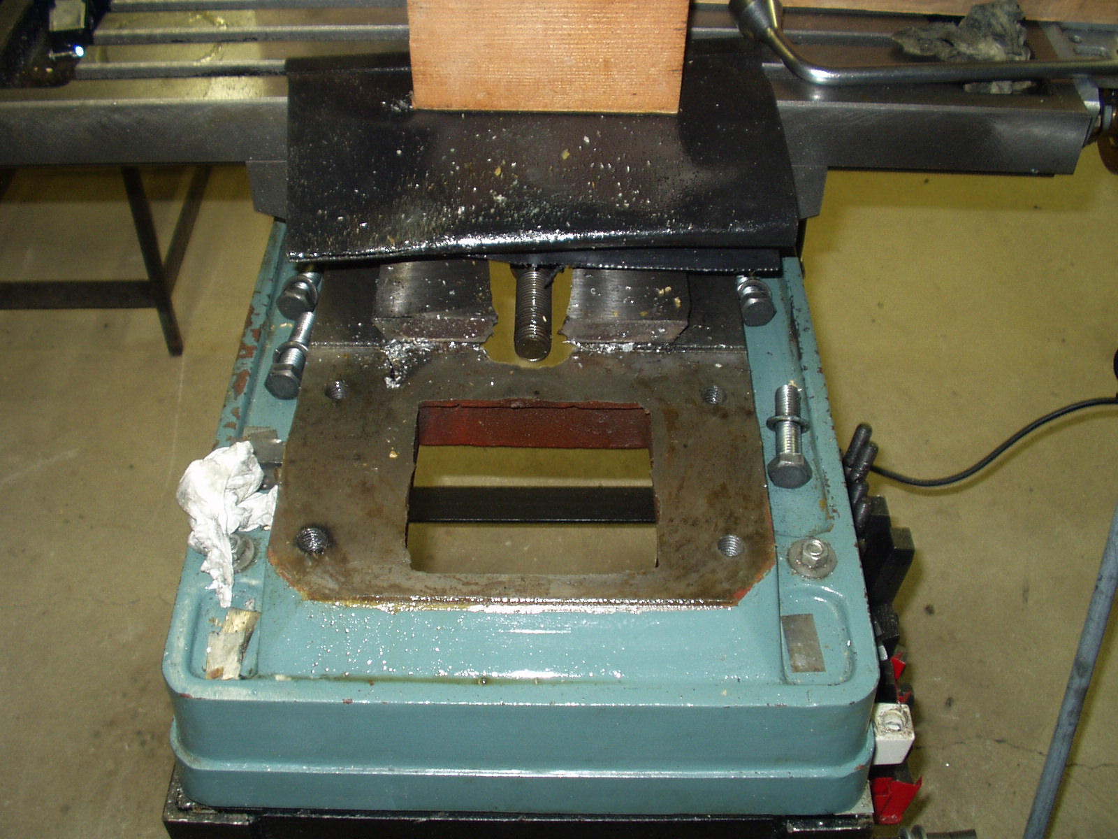
The column was next. Four bolts hold it to the base casting. Then it was a matter of lifting the column up and walking it over to the workbench. Here is the view of the base with the column removed but the table still attached. The cross feed lead screw is visible in the center of the picture. You may also notice a shim in the lower right corner. Adding shims between the column and base casting is how I tram the head. One of the column bolts can be seen just above this shim.
The spindle pulley, idler pulley assembly, and belt shroud were removed first. This shroud is relatively delicate and large. It would have made handling the head difficult plus makes removing the motor a bit awkward.
Consider in figure 1a a quadratic array of circles, representing the atoms. For some reason this array becomes unstable and distorts to the lattice shown in figure 1b.The distortion shown is large, but the area of the array can remain the same. It is a homogeneous distortion of the original lattice in which an atom does not change its position with respect to its neighbors, it only alters their distances. This is characteristic of diffusionless transformations with large shape changes. For these reasons the transformation can be called deviatoric.
Im now 10 years older and maybe a little wiser. It is time to move my mill/drill back into the garage. Is there an easier way to move it this time? After living with this machine for a decade, Ive learned how it comes apart and how to put it back together. Furthermore, gravity will be against me on this trip. So instead of trying to move the machine as a single unit, I took it all apart, moved the pieces, and then reassembled the mill/drill in the garage.
Pearlite
This casting is too heavy for me to safely lift so I used straps and my come-along to do the work. A slight tension was placed on the straps before I unbolted the casting from the support table. Lag bolts that secured the support table to the floor were then removed. The casting was now lifted up about 1 inch making it easy to slide the support table aside. The casting was then lowered onto a special built dolly and secured with the straps.
You may find these weights useful even if you do not have this particular mill/drill. The percentage of total figures should be close if your mill has the same basic shape as mine.
I first raised the base casting up about 2" from the floor on blocks. Two sets of blocks were used, supporting the front and back bottom edges of the casting. Then I slid the scale under one edge, replacing the support provided by one set of blocks. The casting was again level. I took a reading, S1, from the scale. The procedure was repeated on the opposite side to measure S2. The total weight is then just the sum of these two readings. Furthermore, if we define the distance between support points as L", then it can be shown that the center of gravity is X" from the edge raised while performing the S1 weighing:
As I moved the castings, each was weighed with a bathroom scale. The scale is accurate +/- 5% when compared to my beam style bathroom scale.
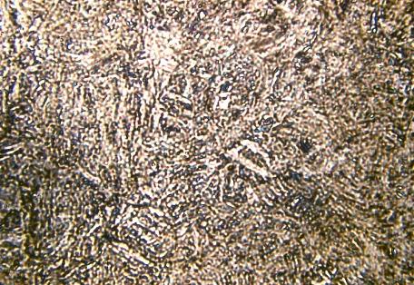
Martensite
The martensite is formed by rapid cooling (quenching) of austenite which traps carbon atoms that do not have time to diffuse out of the crystal structure. This martensitic reaction begins during cooling when the austenite reaches the martensite start temperature (Ms) and the parent austenite becomes mechanically unstable. At a constant temperature below Ms, a fraction of the parent austenite transforms rapidly, then no further transformation will occur. When the temperature is decreased, more of the austenite transforms to martensite. Finally, when the martensite finish temperature (Mf) is reached, the transformation is complete.
Casting name Weight, lbs. % of total head 110 22 column 85 17 saddle 30 6 table 80 16 base 100 20 motor 45 9 Misc. parts 50 10 total 500 100
Next came the head. It was tempting to leave the column and head as one piece but the combined weight was more than I could handle. Others had warned me that putting the head back on the column would be difficult. My decision was to remove the head and deal with re-assembly later. I bolted a length of welded chain to the rafter and connected my 2000-pound capacity come-along. It is not wise to use it in this orientation but given the weight of these separate pieces, I felt it was safe enough (do this at your own risk). With the top cap removed from the column, the head was raised to the top and then lifted off.
Since the casting is symmetric, the center of gravity left to right must be in the center. Knowing the center of gravitys horizontal position is useful when you start to move the casting. The casting can be thought of as a force equal to the total weight concentrated at the center of gravity. If, for example, the center of gravity ends up overhanging a dolly, expect it to flip over at the worst possible time. A variation of this procedure can be used to find the center of gravitys vertical position. Just rotate the casting 90 degrees so the base goes from horizontal to vertical.
Note the long cross bar. My come-along cable ran through the cavity in front of the column and hooked onto this cross bar. The bar is too long to slip out and provides plenty of leverage for maneuvering. Once the head was free of the column, it was a matter of moving it away from the rest of the mill/drill and onto the mills table. I was then able to carry it to the workbench.
Carbide
In order to remove the saddle, start by unbolting the cross feed bearing support. Then unscrew the cross feed lead screw. The cross feed nut must then be unbolted. Then the gib is removed and the saddle slides right off the back.
The head was lowered onto the wood making the operation well controlled and smooth. The motor was then carried to the workbench.
The first step was to take pictures of the mill/drill from every possible angle. Many close-up shots were also taken. This was my insurance policy against having a "senior moment" that might prevent me from reassembling the machine correctly.
Tungsten carbide
Martensite is not shown in the equilibrium phase diagram of the iron-carbon system because it is not an equilibrium phase. Equilibrium phases form by slow cooling rates allowing sufficient time for diffusion, whereas martensite is usually formed by fast cooling rates. Since chemical processes (the attainment of equilibrium) accelerate at higher temperature, martensite is easily destroyed by the application of heat. This process is called tempering. Since quenching can be difficult to control, many steels are quenched to produce an overabundance of martensite, then tempered to gradually reduce its concentration until the right structure for the intended application is achieved. Too much martensite leaves steel brittle, too little leaves it soft.
Aluminum Alloys austenite Corrosion Dislocation Phenomena eutectoid Fe-Fe3C Fe-Fe3C T-T-T Diagram gamma iron Heat Treatment of Steel Hydrogen Embrittlement hypereutectoid Martensite Formation metal casting Metallurgy Glossary pearlite Phase Diagram of Steel Powder Metallurgy proeutectoid ferrite Shape Memory Alloy solid solution stainless steel TTT Diagram Types of Materials
Equilibrium phases form by slow cooling rates allowing sufficient time for diffusion, whereas martensite is usually formed by fast cooling rates. This process is called tempering. Too much martensite leaves steel brittle, too little leaves it soft. The resulting martensitic steel is extremely hard but very brittle. Thus, the martensite is then heated in a process called tempering, which causes the martensite to transform partially into ferrite and cementite.
Ten years ago I bought my new Enco RF-30 Mill/Drill (model 105-1110). My friend and I used a half-ton pick-up truck to move it from the local Enco warehouse to my garage. Then an engine hoist was used to transfer the machine from the truck bed to the garage floor. Ah, that was the easy part. The final destination for my new toy was in the basement. I had to move through our kitchen (without damaging the floor) and down the stairs (without having them collapse). It took a lot of planning but all went well. I did have to re-support the stairs, which took a fair amount of time. I then used the engine hoist to lift up the mill while I slid the support frame under it. Most people who own these mill/drills have a similar story.
I next removed the motor and related switch and wiring. It is not very heavy but I did not want to have to catch it when the last hinge bolt was removed. A shop stool piled with scrap lumber held the motor as I removed the hinge bolts.
The martensitic transformation leaves also characteristic marks on the surface. In figure 8 is shown the surface contrast due to a partial martensitic transformation in an iron-nickel single crystal. The dark bands are the traces of martensite plates that have grown through the sample volume and have intersected with the surface leading to a surface upheaval. The long ones have formed first, and between them shorter ones have appeared whose growth has been impeded by the long ones.
A few words about weighing the mill are in order. All castings except the base were placed directly on the scale. The base was weighed using the following procedure.
This dolly was designed to freely roll around the floor yet could be locked onto a track placed on the stairs. A winch was used to pull the dolly up the stairs. All castings except the saddle rode the dolly up the stairs. A handcart was used on all but the base casting to move the part into the garage. The base casting stayed on the dolly until it reached the door into the garage. Then the casting was slid down a wooden ramp and onto blocks on the floor. The dolly was again employed to move the base to the re-assembly area.
Once the column emerges from the head, I re-supported the end with scrap wood and removed the piece in the way of the head motion. The head is then slid down to the bottom of the column and secured in place with its locking bolts. It sure is nice not to fight gravity.
A crystallographic analysis has shown that the martensite plates have very definite crystal orientations with respect to the original structure. These orientation relationships can nowadays well be accounted for by phenomenological theories, described first by Wechsler, Lieberman and Read, and Bowles and Mackenzie, discussed in the book by Nishiyama and in the book edited by Otsuka and Wayman.
Austenite
Re-assembly was straightforward except for getting the head back on the column. I did not want to try to hold the head in my arms and fish it back on the column along with the rack. Instead I placed the column horizontally and facing down. It rested on two pieces of scrap wood. The head was placed with the back face of the casting on the floor. Next the rack was set into its keyway and engaged with the drive gear. Since the rack is resting on its side, gravity does not try to pull it out. This is one less thing to fight. If the column were vertical, then the rack would tend to fall out of its keyway at every opportunity. Using a slight rocking motion on the head, it was easy to slide the column through the lower opening of the head and up to the start of the upper opening. Any misalignment between column and head becomes evident by looking into the upper opening from the top. Thin wood shims can then be used to adjust the vertical position of the column. Horizontal alignment is achieved with a slight side to side twist of the head casting.
One of the differences between the two phases is that martensite has a body-centered tetragonal (BCT) crystal structure, whereas austenite has a face-centered cubic (FCC) structure. Martensite has a lower density than austenite, so that the martensitic transformation results in a relative change of volume.
The martensitic transformation is a diffusionless phase transition in the solid state with a large deviatoric component. What this means shall be illustrated by a simple two-dimensional sketch.
Martensite is a hard, brittle form of steel with a tetragonal crystalline structure, created by a process called martensitic transformation. It is named after metallurgist Adolf Martens (1850-1914), who discovered its structure under his microscope during his metallographic research and explained how the physical properties of different types of steel were affected by their microscopic crystalline structures. Martensite commonly is found in tools such as hammers and chisels and in swords.


 0086-813-8127573