
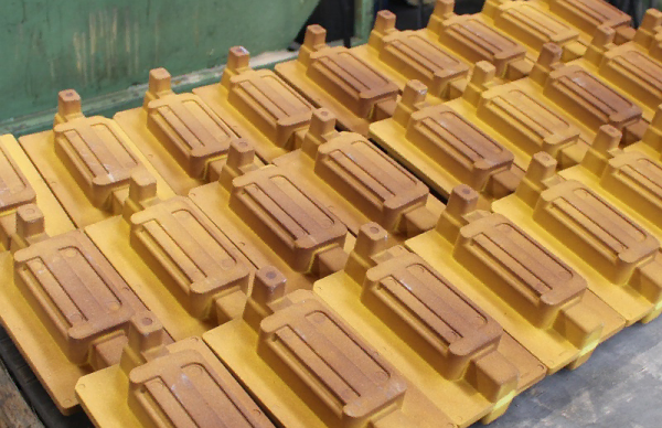
Machine Tool Arbors & Arbor Adapters - slitting saw arbor
A side milling cutter or end mill is used in side milling to shave thin layers of material from the side of a workpiece. This is the way to go for flat or contoured surfaces. Xometryâs very own Aaron (our marketing SVP) explains more about this milling process in the below video.
Face milling is beloved in the manufacturing world because it can be used to make accurate and smooth surfaces, even on larger pieces. It can make pockets and steps in metal by flattening the material and smoothing out the top. A face mill has cutting edges on its face, which is the part that looks like a disk, and these cutters work by shaving off material from a workpiece horizontally until it reaches the depth required (this will be preset by you). This image explains how it works:
Millingmachine
Shoulder milling removes material from the side of a workpiece (the âshoulderâ or âsidewallâ) with different cutting tools, like end mills, to make flat, 90-degree angles, like steps.
Due to the close types of definitions both parameters have, it is possible to confuse them with each other. Some machinists would also refer to this parameter as the difference between speeds and feeds. There are quite a few practical factors that serve as the difference between feed rate and cutting speed. Examples of such factors include:
The cutting temperature is a crucial factor that proves a difference between feed rate and cutting speed. This is because the higher cutting temperature can hamper parameters such as the part’s tool life and surface finish. The extent of the effect of both parameters on cutting temperature and tool life differentiates them from each other. It has a comparatively lower effect on the cutting temperature and tool life than cutting speed for feed rate. Hence, the difference between feed rate and cutting speed is the extent of their effect on cutting temperature and tool life.
Cutting speed is generally defined as the relative velocity between the surface of the workpiece and the cutting tool. Some experts also define it as how fast the workpiece moves past the cutting edge of the tool. Machinists measure it in meters per minute (m/min) or feet per minute (ft/min). The cutting speed is a quite important factor in the determination of other parameters of CNC machining, such as cutting temperature, power consumption, tool life, etc. Its influence in these parameters serves as a significant difference between feed rate and cutting speed.
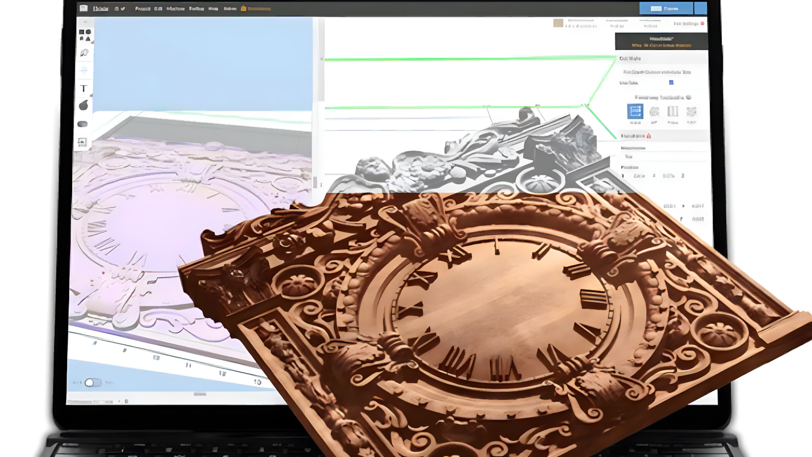
If you have to make complex shapes and profiles on a surface, profile milling will be your best friend. It uses a tool with multiple cutting edges to make curves and angles and also has a ball tip that moves around, smoothing everything out. It sometimes (but not always) uses multiple axes to make the cuts. Getting an axis to cooperate in manual milling is, putting it mildly, impossible, so the process often is used with CNC (computer numerical control) machines. Profile milling is used to make dies, molds, and other parts with more detailed surfaces, like this:
Any cut width that is less than half the diameter causes chip thinning. Chip thinning is a manufacturing defect where the chipload (amount of material cut by the tool in one revolution) is reduced. Chip thinning could lead to a longer lead time; hence it is important to avoid it. In addition, increasing the feed rate will help reduce the effects of chip thinning, hence, increasing productivity and tool life.
Feed rate is the distance which the cutting tool during one spindle revolution. It is also defined as the velocity at which the cutter is advanced against the workpiece. It is measured in either inch per revolution or millimeters per revolution (ipr or mpr) for turning and boring processes. However, machinists use the inches per minute or millimeters per minute (ipm or mpm) for milling processes. In calculating the feed rate, the machinist considers the number of flutes (or teeth) the cutting tool has and calculates the feed rate for each tooth.
Step millingtools
Youâll find that most milling types are self-explanatory with exactly what they do or how they work in their name, but hereâs a little more info on each one.
It might not have a very interesting name, but plain milling is still a useful manufacturing method. Itâs pretty basic, removing material from a surface using a flat, horizontal cutting tool, and it is used for making square or rectangular features. Hereâs what that looks like:
Xometry provides a wide range of manufacturing capabilities, including all the types of milling mentioned in this article, as well as 3D printing, laser cutting, CNC machining, and much more. If you want to learn more about machining or request a free no-obligation quote, reach out to a Xometry representative today.
In geometry, a generatrix is a point or surface that generates a new shape when moved along a given part. The given path through which the generatrix moves is the directrix. In machining, the basic goal is to create geometrical surfaces with aesthetically pleasing finishes and higher accuracy. Hence, these two parameters are required in machining processes. The difference between speeds and feeds is that the cutting speed provides the generatrix while the feed motion provides the directrix.
Types ofmillingprocess
The feed rate also affects the same factors that the cutting speed influences. The only difference is that its effects are to a lesser extent. However, the feed rate is important in the final aesthetic look of the machined part (i.e., the surface finish of the machined part). Hence, its optimization is also quite important in CNC machining processes. To determine its optimum value, machinists consider factors such as the ones below:
There are different lathe tools used for various CNC machining. Each of these tools is also made with different materials, hence possessing different hardness properties. The cutting tool material will have a significant impact on the cutting speed used in a machining process. If the cutting material is of high strength, the machinist can utilize a high cutting speed to a little detriment. However, softer cutting tool materials will tend to wear out quickly with higher cutting speeds. This will lead to shorter tool life.
Straddle milling involves mounting two milling cutters on an arbor and positioning them next to each other to create parallel slots, grooves, or surfaces on your chosen material. Because it has two cutting tools, it can essentially finish a piece in half the time. We see this process used often for keyway milling and machining flats on opposite sides of a shaft.
Form milling makes contoured and detailed shapes on a surface with either a specialized milling cutter in the exact shape or profile you want or generic cutting tools (the latter is a somewhat repetitive process, similar to profile milling). Itâs used a lot in automotive, aerospace, and mold-making, and many times with a CNC machine.
Millingprocess
Angle milling makes beveled edges and angled features on parts. You can use specialized tools with this process, like tapered milling cutters that are cone-shaped or parallel-faced cutters that are flat but can be adjusted at a tilt to get the angle. To get the right tilt, youâd have to use a tilting arbor or four (or more) axis machine.
As you may have guessed, this milling method has been specifically designed to make gears and gear teeth (like the toothed wheels found in car engines or clocks). Itâs done with gear hobbing cutters, or milling cutters, which remove material to make the gear teeth. For simple gears, manual machines are used, but for complex ones, manufacturers tend to go the CNC route.
Determining the optimal feed rate and cutting speed might be the factors that enhance your CNC machining process to get an adequately machined part. However, there is no need for you to worry about any of these production issues when you outsource to RapidDirect. With our experienced machinists and CNC machine programmers, you will always get the best-machined part every single time you work with us. So, reach out to RapidDirect today for all your CNC machined needs.
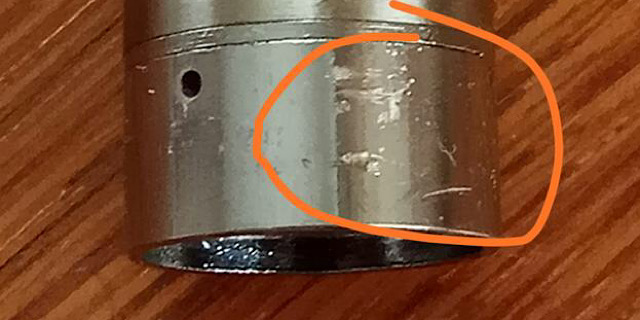
Scallop marks are also known as feed marks. These marks always accompany CNC machined prototypes and parts, and they are the main cause of surface roughness. The feed rate has a direct influence on the scallop marks present on any part. Hence, the higher the feed rate, the higher the degree of scallop marks and surface roughness. However, cutting speed does not affect scallop marks; hence it does not affect surface finishes.
Step millingtechniques
When designing the parts for CNC machining, it is important to consider these parameters. This is because they ensure the optimization of different parts of the CNC machining process. While cutting speed is more important in optimizing factors like tool life and power consumption, the feed rate is vital in determining the machining time and roughness of the finished area. This article will compare feed rate vs. cutting speed and explain how to derive each of them.
The extremely high level of precision needed within the aerospace industry makes CNC machining a suitable manufacturing process for the sector.
ManualMilling
One of the most important factors that determine cutting speed is the hardness of the material being cut. The harder the material, the slower the cutting speed, and vice versa. For example, machining materials like steel will require a lower cutting speed compared to aluminum.
The content appearing on this webpage is for informational purposes only. Xometry makes no representation or warranty of any kind, be it expressed or implied, as to the accuracy, completeness, or validity of the information. Any performance parameters, geometric tolerances, specific design features, quality and types of materials, or processes should not be inferred to represent what will be delivered by third-party suppliers or manufacturers through Xometryâs network. Buyers seeking quotes for parts are responsible for defining the specific requirements for those parts. Please refer to our terms and conditions for more information.
Saw milling works with a large, thin, and round cutting tool that has lots of teeth (like a circular saw blade). This fairly quick and easy process is also known as âslittingâ because it makes thin slits in a material. The blade of the tool can cut straight down in a vertical line or move along the surface for different types of cuts.Â
CNC machining is a subtractive manufacturing process that involves shearing away material chips until the final product is achieved. So first, the machinists need to know the amount of material the machine will shear off in one revolution and the speed at which the CNC machine will move. Here is where the difference between feed rate and cutting speed is important.
The term âmillingâ refers to the manufacturing process of using a circular cutting tool on the ends and sides of a material blank to make a finished part. Thatâs obviously just a very general summation; there are actually around 30 different types of milling operations, 15 of which (the most commonly used ones) weâll go over in this article.Â
If you want to produce high-quality machined parts with a sleek appearance, it’s essential to consider some critical factors related to CNC machining.
The spiraling threads you find on screws and bolts are made with thread milling. The tool has many cutting edges and is able to make threads in many different materials, in all different sizes, and can even tackle more complex designs. The thread milling cutting tool (which, by the way, is known for its durability and accuracy) rotates around the material along the thread path to cut the threads. Its capabilities are pretty much limited to making threads, but it does make them exceedingly well. Hereâs a picture of a thread made by thread milling:
ManualMillingMachine for sale
Gang milling is a little more aggressive, requiring you to mount several cutters on a single arbor. This allows you to cut multiple surfaces or features using a single pass. This is a good method to use if you want to keep productivity high and not have to spend lots of time setting up and handling several individual machines. Itâs great for mass production of identical parts, but would be overkill for low-volume needs.
Step millingmachine
The tool used in end milling has cutting edges on both its end and sides and can make things like slots, pockets, and contours. This method is very common because it is versatile. Itâs a little like a drill bit that can cut straight down (plunging) but it can cut sideways, too. The below diagram will give you an idea of how it works.
It is necessary to ensure that the cutting speed is optimum so that the CNC machining process will give the best part. However, it is possible to predict the optimum cutting speed for a particular CNC machining process by considering other factors. Examples of such factors include:
Slot milling makes slots (like grooves or trenches) in any size with a slot cutter which looks like a circular saw blade. This will cut into the sides of the materials to do the job, but you can also use an end mill that cuts on its side and face. It basically carves out a channel in the material, making things like the slot your keys go into (keyways) and other grooves, like this one:
How long the machinist wants the tool to last is another factor that is important in determining the cutting speed. This will include considering variables such as how much the tool cost and the cost of the tool compared to the quantity of parts being produced. If variables like this are favorable, then a high speed might be feasible for use.
CAM (computer-aided manufacturing) milling can make parts that most humans would find impossible to create by hand. Itâs an automated process, with the cutting tool being controlled by a computer. Human effort is only needed to design the digital blueprint for the part with exact instructions on how to make it in the language that it can understand (donât worry, there are tools for this) and then feeding it to the computer and switching it on.
This picture shows all the parameters involved in the determination of cutting speed and feed rate. You’ll notice that the spindle speed is the foundation of determining both the cutting speed and feed rate. Also, the feed rate involves two formulas before arriving at the final answer. First, you have to determine the feed per tooth. That value is then used to determine the feed rate of the cutting tool.


 0086-813-8127573