
Metala Wine » In Stock | Cellarit - metala stock
Did you know that the chips your end mills make get thinner if you reduce the cut width below half the tool’s diameter? Here’s a graphical depiction of this strange phenomenon, which is called “radial chip thinning”:
Recall that Niagara Speeds & Feeds Chart. It calls out the soft and hard grades of the workpiece material, and the surface speeds vary quite a lot between the two. But, this is another oversimplification due to the shortcomings of trying to present this sort of information on paper. The truth is that there are probably thousands and thousands of different workpiece materials to consider. And it isn’t just two ranges.
CA Residents: Prop 65 Warning(s)Many metalworking products contain chemicals or metals included in the latest Prop 65 warning. Exposure may cause cancer and reproductive harm. KBC is currently gathering required California Prop 65 warnings for our customers. For more information go to www.P65Warnings.ca.gov
Being able to do so cheaply and in far less time than it’ll take you to punch the numbers up in your spreadsheet is nearly priceless. If you haven’t already, take our G-Wizard Feeds and Speeds Calculator for a free 30-day spin. It takes care of every one of the pitfalls we’ve discussed and does a whole lot more. You won’t be disappointed, I promise!
For example, suppose that the drawing depicts a round insert viewed from the side, perhaps for a button cutter. Or a ballnose endmill tip. Yes, you’re starting to see.
Cutting speedcalculator
The answer is a good Feeds and Speeds Calculator will automatically identify the “Sweet Spot” where the power and allowable feeds and speeds maximize your Material Removal Rate.
That just leaves the Feedrate, but it’s pretty easy too. See our free simple turning speed and feed calculator for more. In fact, we have several free simple speeds and feeds calculators:
The simple formulas (and calculators) don’t work for every cutter type. How about saws? Slitting saws, slotting saws, and keyseat cutters all use a particular and unique set of calculations for their feeds and speeds. I’ll bet you use more tool types than simple end mills. Do your feeds and speeds solutions work for all of them?
Back-solving can be very important where machine limits are encountered. Sometimes we need to work backwards from a limit to see how it affects all the other values in the calculation. But, making formulas work in reverse, especially when we have a large and complex network of intertwined formulas is not easy. It requires very sophisticated math to make it all work out.
Feeds and speeds are the essential parameters that determine how a particular cutter will cut through the particular type of material found in the workpiece being machined.
I manually bumped the chip load down from the chip thinning-adjusted value G-Wizard would normally give. Now further, let’s suppose I decide to run things even more conservatively, so I take the feed rate down to 1/10 what it was. I’m only going to move at 4 inches per minute. Now G-Wizard is giving me a warning:
Notice the SFM range runs from 800-2000 on “Soft Grade” aluminum. That’s a factor of over 2x! If you guess run and find yourself running 2x faster than the tool should be run, guess what that’s going to mean for your tool life? Not good, right? Now there are a bunch of rules at the bottom that call for you to modify both the surface speed and the feed based on:
That much is true, and you’ll need to speed up your feed rate to compensate for the chip thinning if you want to keep your productivity up. However, chip thinning taken to the extreme can be very hard on tool life.
High Performance Inserts ; P · P · Steel ; M · M · Stainless Steel ; K · K · Cast Iron ; N · N · Non-Ferrous Materials ; S · S · High-Temp Alloys ...
Today, it’s hard to be competitive without using HSM. Even hobbyists have ready access to this valuable technique with Fusion 360. But, don’t use conventional feeds and speeds with HSM. It changes things on so many levels as my article and video on HSM explain.
– You can rely on data from the Tooling Catalog feeds and speeds chart. That data is important, but used by itself, it’s also loaded with limitations. For example, a feeds and speeds chart is a 2-dimensional table. It can only cover 2 variables.
A Harvey Performance Company ... Tool # 16448-C3 ... Dovetail Cutters, Specialty Profiles.
Harbor Freight is America's go-to store for low prices on power tools, generators, jacks, tool boxes and more. Shop our 1500+ locations. Do More for Less at ...
Our G-Wizard Feeds and Speeds Calculator covers 60 variables! When was the last time you looked through 30 charts to figure out recommended cutting speeds? You basically can’t do it, which is why:
You may need to adjust even when comparing Feeds and Speeds on two different industrial machines. This is true for all sorts of reasons such as:
Dec 25, 2019 — The flat head bit that came with the cordless drill has been great, made this a lot easier. in that it basically turned the drill into a powered screwdriver.
For example, if you’re running a surface speed of 800 surface feet per minute, and a tool diameter of 1/2″, your spindle speed (RPM) should be:
If you haven’t guessed by now, Simple Formulas are not all that great when it comes to Feeds and Speeds. Even spreadsheets, however complex you try to make them, are very limited.
Having good Feeds and Speeds is absolutely critical to successful machining–the cutting process of your machine tool will fail without them.
For example, they might tell you the numbers and then let you know that there’s a better way. They might remind you of some other considerations, for example, that the cut might be likely to rub, or that those parameters are a risk for tool deflection or a myriad of other things.
Less Depth of Cut means you can afford to be more aggressive. But, even correcting for that, what are we supposed to do when Axial Depth is say 0.75 Tool Diameters? They don’t say.
But all coolant is not equal. For example, the coolant needs to be aimed properly. They make technology in the form of Programmable Coolant Nozzles to facilitate proper aim. Even better, there is technology to put the coolant right down at the bottom of the cut where it can do the most good. This is called Through Spindle Coolant because it uses passages to direct the coolant through the spindle, into the tool, and out at the very bottom of the cut.
What is the Feed Rate Formula? Feed Rate Formula: Feed in ipm = Spindle RPM x Feed Per Tooth x Teeth in Cutter What is the Cutting Speed Formula? Cutting Speed Formula: Cutting Speed in RPM = (Surface Feet Per Minute x 3.82) / Tool Diameter in inches What is Chip Load Formula? Chip Load Formula: Chip Load (IPT or Inches Per Tooth) = ( Feedrate (Inches Per Minute) / RPM) / Cutting Edges
Our Feeds Calculation is then 6112 * 0.001 * 4 = 6.112 * 4 = 24.448 inches per minute as our calculated feed rate. Exceeding that feed rate will likely jam the cutter with too many chips and potentially snap it off. You don’t want to slow down the feed rate too much because we want to avoid rubbing at all times.
– You can build or borrow a spreadsheet. This is the least popular for reasons I’ll discuss. Basically, it’s a lot of work for a lot of limitations.
Coolant. Every CNC’er is familiar with it. But did you know its two most important purposes aren’t cooling? That’s right. The two most important purposes are chip clearing and lubrication. If we can’t clear the chips well enough from a cut, eventually they’ll pack up in the flutes of our cutter. They’ll jam, and not long after, the cutter will break. Ouch! We all hate when that happens.
Tool Meterial compensation can be done in the manufacturer’s tables for surface speed and chipload. But like so many things, there are a lot of exceptions where just following the simple math will get us into trouble.
CA Residents: Prop 65 Warning(s)Many metalworking products contain chemicals or metals included in the latest Prop 65 warning. Exposure may cause cancer and reproductive harm. KBC is currently gathering required California Prop 65 warnings for our customers. For more information go to www.P65Warnings.ca.gov
– By far the most popular option is to use a Feeds & Speeds Calculator such as our G-Wizard. Good feeds and speeds can do things that simply are not possible any other way, so it’s not surprising that the most powerful tool is also the preferred tool. If you’re ready to accept a Feeds and Speeds Calculator and want to move on and learn other things, click here.
Formula cutting speedin mm
Here’s the reality: Manufacturer’s Tooling Catalogs are limited by the format in what they can present. Tables are only good for showing 2 dimensions. They add rules like the ones described to try to make things more flexible and fit the cutting physics better. But, the actual cutting physics is quite complex.
There are variances in every job and if you’re locked into just a few standard cuts, you’re missing out on the possibilities. BTW, one of the reasons CAM does such a lousy job is it takes the approach of databasing standard cuts. Every job is different.
Cutting speed formulafor turning
Here’s another one. Suppose you have a Face Mill with a diamond-shaped insert. It presents a 45-degree edge to the cut instead of a 90-degree square shoulder. That 45 degrees is called the lead angle, and it affects your Feeds and Speeds quite a bit.
Feed rateformulafor milling
Steve Craig is an inventor, artist, designer, photographer, builder, and maker of interactive art machines for kids. His creations include a crane, ...
CA Residents: Prop 65 Warning(s)Many metalworking products contain chemicals or metals included in the latest Prop 65 warning. Exposure may cause cancer and reproductive harm. KBC is currently gathering required California Prop 65 warnings for our customers. For more information go to www.P65Warnings.ca.gov
One of Niagara’s rules for adjusting speeds and feeds is when the Axial Depth is between 0.25 to 0.5 Tool Diameters, use 80% of the lowest SFM range. But when Axial Depth is equal to or greater than Tool Diameter use 80% of the highest speed range. Now for starters, it sounds to me like they have that backwards.
– About the same number use Machinery’s Handbook. It’s pretty antiquated, especially for CNC applications. You can do better.

Feeds corresponds to the feed rate, while Speeds corresponds to the Spindle Speed. Feed rate is typically measured in some length value (inches or mm) per unit of time (minute). So, for example, IPM (Inches Per MInute) is the most common Imperial Measure. The Spindle Speed is measured in rpm’s.
Well, the expert will. Formulas won’t. But somewhere in between, great software can remember all that and try to offer it up to you at just the right moment.
Ask any good expert the answer to a question, especially something like an exact feeds and speeds scenario, and they’ll give you a good answer. But, they’ll very likely give you more than just that answer.
Formula cutting speedchart
You need to smoothly adjust your surface speed and chip load for every possible point on the 2 dimensions that make up Cut Depth and Cut Width. There’s no way that can even be shown on paper charts.
And don’t even get me started with CAM software. So many CAM packages now purport to do Feeds and Speeds, but under the covers, they’re just running simple cutting speed formulas. You can do a lot better. And, you should.
Even a spreadsheet, as powerful as they are, has a hard time with back-solving. If you’re going to be able to handle feeds and speeds problems that require back-solving, you’re not going to be able to use simple cutting-speed formulas or even a spreadsheet. You will need software that can do it directly.
The Cutting Speed Formula may be simple once you have all the parameters, but finding the proper values for the parameters is a lot harder than it looks. I know many of you are leaning forward about now and thinking something like, “Now Bob, it’s just not that hard to look up the manufacturer’s recommendations for the cutter.” It isn’t, but those recommendations aren’t that helpful because they give you big broad range of values in many cases. Take this speeds & feeds chart from Niagara Cutter:
– You can rely on sound or feel. This requires quite a lot of experience and even though it has its devotees, it basically doesn’t work. If it did, you could buy “ear training” CD’s for machinists and Boeing would require you to pass a feeds and speeds by ear audio test before they would hire you.
SFM: Surface Speed (Surface Feet per Minute). This comes out of the manufacturer’s tooling catalog or generic charts and is based on the tool material. workpiece material, and the particular model of the tool.
One of the great wonders, if you think about it, for hobbyists is they can buy and use the same cutters as professionals. That’s pretty awesome because it makes it that much easier for the hobbyist to succeed. But, same cutter or not, if you place the cutter in a tiny little hobby CNC machine versus an expensive and heavy industrial CNC machine, it won’t perform the same.
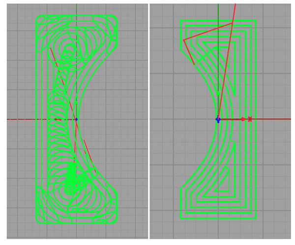
You can have similar chip thinning effects there. What about the speed of a ballnose that’s cutting less than half the diameter deep? That’s an interesting case because it means the tool has an effective diameter of potentially a lot smaller tool. Take a 1/2″ ballnose and cut 1/8″ deep and the effective diameter of the ballnose is now 0.433″, not 0.5″.
– You can rely on standard cuts that worked in the past or rules of thumb. This method is pretty popular, but it sure is limiting. After all, are all of the pockets you cut the same depth? Do you know all the many conditions baked into the rule of thumb and do they match your specific cutting process?
It has to be a calculation. Many manufacturers realize this and wind up telling the machinist that the catalog values are just a recommendation and that the machinist will need to use their judgment to decide exactly where on the range of values they should be for a particular cut.
Cutting speed formulafor drilling
– Amazingly few use their CAM software, even though most CAM has provision for it. The reason is simple. As we uncovered in our CAM Software surveys, most CAM software does a truly lousy job with feeds and speeds. It’s pretty easy for you to do better.
Ideally, every single alloy and condition (heat treatment or other hardening) of workpiece material would have its own speeds and feeds chart. That’s the only way to accurately capture that information. What we’re looking at is a Material Database, not a simple tooling brochure. Having a good one makes a huge difference in machining quality.
In the first 5 lessons you learned the basic terminology and behavior of Feeds & Speeds. By now you’re probably way past ready to start figuring feeds and speeds.
Once again, the simple cutting speed formulas are not helpful. They’re mute about these things. But, these are things that are well understood and can be factored in.
OK, for cutting parameters let’s keep the 6112 RPM from above, make our recommended chip load 0.001″ and assume we have a 4 flute cutter.
Bob is responsible for the development and implementation of the popular G-Wizard CNC Software. Bob is also the founder of CNCCookbook, the largest CNC-related blog on the Internet.
None of that happens because you can only hear bad feeds and speeds. You can’t hear somewhat bad and you sure can’t tell the difference between ok and awesome feeds and speeds.
Dec 16, 2022 — Stainless and alloys like chainsaw bars are made of work harden. So if you let the bit slip across the surface you'll harden the metal to more ...
Formula cutting speedcalculator
Please take a look at the screenshot above where G-Wizard has three tips for us. It wants us to use Climb Milling, it reminds us to use coolant or mist to lubricate when we’re cutting aluminum (otherwise chips can weld to the cutter), and it warns us we’re in danger of rubbing.
Your machining quality is extremely dependent on having good feeds and speeds, so understanding the pitfalls is just as important as making the calculations.
Remember that chip thinning diagram at the top of the article? As I mentioned, it depicts an endmill looking straight down the spinning axis. But the geometry matters for other cases too.
That’s all very easy, right? And, for a fair number of machinists, they think that’s all they need to figure the Feeds and Speeds for their cutters. For some things like compensating for Tool Material and Coating, the simple formulas do a good job.
High Speed Machining (HSM) is nothing short of magic when it comes to speeding up jobs and even, in many cases, improving tool life at the same time. However, there is no simple cutting speed formula available to give proper feeds and speeds for HSM. Before there were good HSM Feeds and Speeds Calculators like G-Wizard, you had to just look at a bunch of scenarios others published and try to pick one close to your situation.
Thought Catalog is a digital magazine based in Williamsburg, Brooklyn. Over 30 million readers every month turn to us for inspirational, honest, and heartfelt ...
Join 100,000+ CNC'ers! Get our latest blog posts delivered straight to your email inbox once a week for free. Plus, we’ll give you access to some great CNC reference materials including:
FPT: Feed per Tooth (Chipload). This comes out of the manufacturer’s tooling catalog or generic charts and is based on the tool material. workpiece material, and the particular model of tool. Note that the chipload will be the expected chip thickness of each chip being sliced off the part. This is subject to some fiddling when chip thinning occurs.
The simple cutting speed formulas all assume square endmills, yet there are so many cutters that aren’t square at all. The calculations have to be adjusted, often in quite complex ways, to account for the differences.
The reason? Let’s imagine a new machinist. They’ve got a lightweight CNC machine, they’re just starting, and they want to take it easy. So, they keep the Cut Width very light. Let’s say only 10% of the cutter width. Here’s what the Feeds and Speeds look like without the chip thinning adjustment:
The practical ramifications of all this mean that if you prefer to go with the basic formulas for speed recommendations, perhaps because it seems easy, you will deal with reduced tool life and material removal rate.
You can do one better than that even by cranking the pressure of the coolant way up. All of this can profoundly affect the cut if your machine is equipped with such options, but the normal cutting speed formulas say absolutely nothing about the effect of coolant.
Chip thinning can drive down chip load so low that the tool begins to rub instead of cutting. If you want to read more about radial chip thinning and rubbing, try my article on the subject that’s part of our Free Feeds and Speeds Course. I even did a video on chip thinning for Cutting Tool Engineering.
People want things their way. It’s just human nature. And when you’re talking Feeds and Speeds, there’s a lot of adjustment. There’s really not just one answer until you consider those adjustments. This is particularly true when we think about roughing versus finishing and the tradeoffs between aggressive material removal rates, surface finish, and tool life.
Solid carbide tap drill 2,5-10,2mm TIN (for M3-M12), 7-piece · Drill bit for extracting broken-off taps · For drilling stellites and heat-treated steels (58 – ...
(800 x 3.82) / 0.5 = 3056 / 0.5 = 6112 RPM. Exceeding this maximum speed for your milling operation will likely overheat your tool which drastically reduces tool life.
Most CNC Lathes can maintain a constant surface speed (CSS). This constant speed is Surface Feet or the metric equivalent. This greatly simplifies cutting speeds because you just enter the constant surface speed and the lathe dynamically varies spindle speed to keep the cutting matched to that CSS number.
You get the idea. The cutting speed formulas don’t say much of anything about what to do to compensate for these differences, or what to do when a limitation is encountered. What do we do if the machine’s minimum rpm is much greater than the rpms recommended by the cutting speed formulas? How can we compensate for the lack of rigidity on a lightweight machine?
Do you ever go through tooling catalogs and read the Technical Information in the back? They’re chock full of great tips and techniques. Except, who can ever remember them all?
In the diagram, you’ll look straight down the axis of the endmill and compare two cuts. The blue shows how much thinner shallow-cut chips are versus full-width (red segment). This may seem pretty harmless. At worst, it seems like using these thinner cuts may be leaving money on the table.
Here’s another head scratcher. Suppose your Industrial CNC has a pronounced torque curve on the spindle. If you run the feeds and speeds simple formulas predict you’re way off the power peak. You know you’ll do better if you run where the power is, provided the feeds and speeds for that area are still fast enough. But how do you figure that out?
According to Kaplan the answer is glycine b/c it has the least steric hinderance. The Kaplan book states that only proline is an α-helix breaker.
Cutting speed formulaPDF
Cutters are not cheap and neither is your time. Being able to get not only better performance but longer life from your cutters is worthwhile–proper cutting speed matters!
RPM: Revolutions per minute. The rotational speed of the tool (spindle speed when milling and drilling) or workpiece (turning).
The controller uses the tool position in X to determine workpiece’s outer diameter (or inner diameter) and thereby calculate spindle speed. It will ensure that the given surface speed is automatically used no matter what diameter is being turned.
Feb 22, 2022 — ... 76815, 76816 and 76817 for ... Without appropriate diagnosis codes supportive of medical necessity, ultrasounds for procedural codes 76811, 76812, ...
This article gives you all the cutting speed formulas you need for basic feeds & speeds, but it also shows you the pitfalls of using them.
A fair amount of additional calculation is being done there, but by the way, it’s still not enough because the values are not interpolated. With a dedicated feeds and speeds calculator like G-Wizard, their internal models and calculations to deal with actual machining circumstances are quite sophisticated by comparison.
We thought it was worth asking, “How do machinists determine Feeds and Speeds?”, so we surveyed our readership and here’s what they said:


 0086-813-8127573