
Microtool, Inc. | 913-492-1588 - micro tool company
The seventh position indicates a radius or a facet. Radius is given as 1 * 64 of an inch: 0 – sharp corner (0.002″ maximum radius); 0.2 – 0.004″; 0.5 – 0.008″; 1 – 1 * 64″; 2 – 1 * 32″; 3 – 3 * 64″; 4 – 1 * 16″; 5 – 5 * 64″; 6 – 3 * 32″; 7 – 7 * 64″; 8 – 1 * 8″; 10 – 1 * 16″
The width and length dimensions of rectangular and parallelogram inserts are used instead of the I.C. The size of these inserts is indicated by a two-digit number. A first digit indicates how many eighths of an inch the insert is wide and a second digit shows how many fourths it is long.
There must be a simple system devised to categorise carbide inserts for their use since the sheer variety of carbide inserts on the market and their precision use require it. A series of letters and numbers are engraved on the centre of all steel cutting inserts, including carbide turning inserts. It refers to the ISO code system for turning tools that provides a simple method of identifying carbide inserts that can be used for narrowing the search for inserts. We discuss in this article a system of codes used to identify carbide inserts, and how I advise you to use the code system to identify your inserts.

In order to protect and maintain the integrity of ceramic materials, precautions must be taken in the use of machines to keep excessive vibrations to a minimum. Ceramics are naturally more brittle than carbide alternatives. The ceramic compound is augmented with additional components that prevent this brittle tendency and increase its longevity.
Acmethread angle
The tungsten carbide used in cemented carbide is melted at an extraordinarily high temperature inside moulds. For saw blade tips, the moulds have pockets. These cemented carbide tips are then removed from the mould, placed on the saw blade tips, and brazed into place. A very sharp cutting edge is then created by grinding the tips. Except for the coating used on the tips, ceramic blades are formed the same way as carbide blades. There are also ceramic blades without teeth and with completely smooth edges. Blades with ceramic coating have very small diamonds embedded in the edge or tip. Diamond blades are commonly referred to as such because of this feature.
The main difference between Seller's thread form and Whitworth's is that the tops and bottoms of the threads (the crests and roots) are flattened. The flattened root was a bad choice. Such angular configurations in metal concentrate stress and the process of manufacture result in high stresses at the roots of threads anyway. The result is cracks and broken fasteners. This problem was not so noticeable in Seller’s day thread roots tend to be rounded anyway as the tools that make the bolts become worn. Round roots are now the norm in the USA and the thread is described are UNRC, UNRF the “R” for round root.
In the sixth position, there is a significant one- or two-digit number representing the thickness of the insert in sixteenths of an inch. Whenever the thickness of a piece is a whole number: 1 – 1 * 16″; 2 – 1 * 8″; 3 – 3 * 16″; 4 – 1 * 4″; 5 – 5 * 16″; 6 – 3 * 8″; 7 – 7 * 16″; 8 – 1 * 2″; 9 – 9 * 16″; 10 – 5 ⁄ 8″.
About us Contact us Sign Up Home Page Advertise Promote Brochure Advanced Search Site Issues Privacy Policy Site Map
Thread angle chartcalculator
In particular, ceramic inserts are much superior to carbide inserts when it comes to heat resistance. The ceramic insert category encompasses several variations, but, generally speaking, all of the options fall under the category of providing solutions for the machining of extremely hard metals. Since ceramic inserts are heat-resistant, they can be used for lower production times as they are capable of cutting continuously at higher speeds due to their heat resistance. Due to reduced production times and lower costs, ceramic inserts are a good choice.
Milling Feed Rate (Also called Table Feed and Feed Speed), is the linear velocity of a milling cutter relative to the workpiece, measured in [mm/min] or [inch/ ...
You can take advantage of inserts carbide in numerous possible ways. You can use carbide lathe inserts for machining various materials.
Squarethread angle
Fourteen standard types of insert are referred to using capital letters, and these variations include fixing holes, countersinks, and special features on rake surfaces.
With its high accuracy and high-performance indexable inserts, the Drilling and Hole Boring System is suitable for use on materials as diverse as aluminium and superalloys. With the drill body made of heat-treated steel that is very rigid, the nest for the insert is rigid and the flutes are straight, resulting in a long term life for the insert and an efficient chip removal process.
Among the multitude of applications for which groove-making tools are relevant, there is a vast variety of hardware components of all types. These Carbide specialists specialize in determining the precise specifications required to perfectly suit the needs of each customer, regardless of whether they are parting off a smaller component or creating a deep groove with a large diameter. A Carbide insert can be grooved efficiently and expertly for extrusion grooving, internal grooving, face grooving, as well as parting. To maximize productivity and efficiency, you need to make sure that you choose the right tool. Every groove comes with its own set of challenges, no matter how wide or shallow it is. Additionally, every material used in the manufacturing of the component has its own set of properties and limitations. It is these three elements that truly determine how the ideal tool should be designed, sized, and rated for the job.
In addition to its high cost per unit, carbide is also very brittle, making it more susceptible to breaking and chipping when compared to other typical tool materials. Due to these factors, carbide cutting tips are often provided as small inserts within larger cutting tools that have steel hilts. The shank of the hilt is usually made of carbon, which is a more suitable material for the shank of the carbide cutting tip. As such, the carbide surface at the cutting interface is able to provide the benefits of using carbide without incurring the high costs and brittleness of making the whole tool from carbide. As with many of the modern lathe tools and endmills, most face mills these days have carbide inserts as well in them.
It is ultimately determined by such factors whether or not you will achieve satisfactory chip control and machining results.
The die threads penetrate the blank surface to form the thread roots and displace material radially outward to form the crests. Metal is neither removed nor wasted but displaced.
If you are planning on using a carbide insert when you are cutting particulates or foam, you will have to make sure you choose the right insert. A preventative method can reduce the number of damage cases to the insert, as well as the machines as well as the workplace in general. Among the different styles, sizes and grades of cutting tools available in the market today.
Buttressthread angle
Maudslay took on Joseph Whitworth as an apprentice, who proved exceptionally talented. He next worked at Joseph Clements, where they were trying to build Babbage's calculating engine, the first computer, and finally set up shop for himself as a toolmaker.
Additionally, these tools can be removed from the tool body, which means that the tools are not welded or brazed together. This type of tool can be used at high speed, which means you can create better surface finishes on your materials as a result of faster machining.
A turning tool body grips a replaceable insert which is attached to a lathe turret. Turning is typically done with a replaceable insert. Inserts for turning tools are manufactured using composite materials, coatings, and geometry features that provide high accuracy and high material removal rates.
Carbide blades can be used to cut through wood, plastic, and metal, as well as a variety of other materials. Choosing the right blade for your material allows you to get smooth cuts using hard carbide tips. In terms of blades, the number of teeth, their shape, and if they are rounded or pointed, make a difference. It can be sharpened and reused for a long time when used correctly. On the contrary, the typical application of Ceramic Blades is to cut ceramic tile, porcelain marble, concrete, and masonry. They have a diamond coating that provides very clean and smooth cut results. Wet or dry applications are possible with this type of ceramic blade.
According to ANSI B212.4-2002, there was an additional capital letter O, which denoted other relief angles for design changes to indexable inserts.
Titan Distributing is a Retail, Pharmaceutical Manufacturing, and Consumer Goods company located in Horn Lake, Mississippi with $5.7 million in revenue and ...
Tool Holders ... This fully stocked Harvey Tool product offering of Saw Arbors - Straight Shank allow for chucking at multiple depths. Order a Saw Arbor, and a ...
Coatings are sometimes used in order to increase the lifetime of carbide inserts. Generally, coatings designed to increase a tool’s hardness or lubricity will also increase the tool’s lubricity. By coating a cutting tool, it will be possible for the cutting edge to pass cleanly through things without the material galling or sticking to it. Besides lowering the temperature associated with the cutting process, the coating will also increase the tool’s longevity by preventing the tools from getting stripped out. As a rule, the coating is deposited using either thermal CVD or mechanical PVD methods, both of which are usually done at lower temperatures, depending on the application.
A capital letter indicates 10 positions in the indexable insert as per the ANSI B212.4-2002 standard. There are ten positions (1-10), which define the characteristics of an insert as follows:
In addition to thread mills and thread rolling, the use of thread inserts is another method for creating threads on a workpiece similar to thread milling. It is important to put these replaceable commodities in their proper places as replacements wear out.
dimensional data and technical information shown on the fastenerdata website is in the public domain and has not been acquired through the standards agencies, it has been completed and compiled by fastenerdata and is for guidance only; where discrepancies are found they are subject to change without notice. fastenerdata makes no warranties or representations regarding the accuracy and validity of such information and data, and in order to ensure your interest we suggest you contact the relevant standards authority for total accuracy, fine detail and supporting information. fastenerdata is supported by paid advertisers and all pages may contain paid or sponsored content
In the ninth position is a capital letter that indicates the hand of an insert: R – Right Hand; L – Left Hand; N – Neutral.
Thread angle chartmetric
As the material integrity of ceramics has been improved, ceramics can be a viable alternative to carbide solutions, improving the life of the material to a similar duration as that of carbides.
Typically, carbide particles are bonded together with a metallic binder in order to create carbides that are cemented together. The carbide particles act as aggregates and the metallic binder acts as the matrix. Sintering means the combination of the carbide particles with the binder, so it is a technology that combines the particles with the binder. The binder in this process gradually enters the liquid phase, while the carbide grains (which have a much higher melting point) remain in the solid phase. In reality, the binder is cementing the carbide grains, creating a metal matrix composite with the distinct material properties that it requires. Taking advantage of the naturally ductile property of metal binders, to offset the characteristic brittle nature of carbide ceramics, is one of the best ways to increase their toughness and durability. The carbide parameters can be modified significantly in this manner within the sphere of influence of the carbide manufacturer, mainly depending on the grain size, the cobalt content, the dotation, and the carbon content.
Thread angle chartin mm
JavaScript seems to be disabled in your browser. You must have JavaScript enabled in your browser to utilize the functionality of this website.
When choosing carbide shapes, consider the highest possible nose angle to ensure the longest possible life of the insert.
When the seventh position contains letters, the 10th position will only be used. The number represents a nominal measurement of sixty-fourths of an inch in length: 1 – 1 * 64″; 2 – 1 * 32″; 3 – 3 * 64″; 4 – 1 * 16″; 5 – 5 * 64″; 6 – 3 * 32″; 7 – 7 * 64″; 8 – 1 * 8″; 9 – 9 * 64″; 10 – 5 ⁄ 32″.
A carbide insert is a cutting tool is tool that is used for machining different metals, such as cast iron, steel, carbon, non-ferrous metals, and alloys with a high melting point. The inserts of a carbide cutter are indexable, which means they can be swapped, rotated, or flipped without affecting the geometry of the cutting tool.
Inserts made of cemented carbide are available in several sizes, shapes, and compositions that are used in various manufacturing methods on steels, cast iron, highly ferrous alloys, and nonferrous metals. In addition, machining metal parts more efficiently and with better finishes can be done when using carbide inserts. In addition to steel, stainless steel, hardened steel, cast iron, non-ferrous metals, titanium, and boring inserts are also good choices for applications.
The carbide insert thread mill is the term used to describe a piece of cutting insert that is used to create an internal or external thread within a part. These are typically attached to a tool holder on a lathe or a turning centre, where they are normally used with tools.
Besson in France contrived a screw-cutting gauge to be used on lathes in 1569. In 1641, screw cutting was further improved by Hindley of York, England. In 1760 Job and William Wyatt took screw cutting a stage further. Henry Crum Patent the same Wyatt machine in the USA 76 years later in 1836. Henry Maudslay's career began in 1789 as a blacksmith, making machinery for Joseph Bramah the famous locksmith. When Henry Maudslay later went on to establish his own company, his work was influenced by precision. In the early eighteenth century machines were primitive, there were no standard measures, parts would have to be individually engineered, nuts and bolts would be made to fit as a pair and were not interchangeable. Henry Maudslay was among one of the first to recognise the importance of standardisation and interchangeability of machine parts, his major engineering contribution was his large screw-cutting lathe. Henry Maudslay's lathe was far superior to any of its predecessors and as such, it became widely used. It is not surprising therefore that Joseph Whitworth chose Maudslay's works as the starting place for what was to become his very successful career.
Mar 5, 2024 — Norseman by Viking are by far the best that I have used, and they are not really expensive for what you get if you shop around.
NEIKO 00823A Diamond Hole Saw, 5 Pc Diamond Drill Bit Set, 5/32–1/2-Inch Hollow Core, 1/4-Inch Shank, Glass Drill Bit, Ceramics, Tile Drill Bits, Granite, Glass ...
Thread angleformula
One of the newest materials using carbon fiber and resins is called CFRP (Carbon-Fiber Reinforced Polymer). Due to attractive properties, such as weight-to- ...
Jan 8, 2024 — Tools Related to the Power Drill ... Other useful tools for making holes include the hand drill and various small saws. Tools useful for turning ...
Five digits indicate the diameter of the inscribed circle (I.C.) for all inserts that have a true I.C. such as Rounds, Squares, Triangles, Trigons, Pentagons, Hexagons, Octagons, and Diamonds.
Letter A, B, and T indicate the tolerances on the dimensions (* from nominal). Insert dimensions are given by Dimension A. Inscribed circle diameter is given by Dimension A. Dimension T is the thickness of the insert. As a result, dimensions A and B are the corresponding dimensions for pentagonal, triangle, and triangular shapes.
An ideal nose angle would be a big one but it would be more complicated and require a lot more resources. Furthermore, it would be more likely to cause vibrations. As a result, a small nose angle will have a low cutting edge engagement and may not perform as well as a large angle. It is, therefore, more prone to the diverse effects of heat and has a heightened sensitivity to them.
A number of parameters must be taken into consideration when choosing the right carbide inserts. It is possible to find China carbide inserts manufacturers who provide quality material, but why take the chance? It is possible to find China carbide inserts manufacturers who provide quality material, but why take the chance?
A cylindrical blank having an outside diameter between the major and minor diameters of the finished thread is rotated between hardened steel dies bearing the reverse thread form.
Threads are produced with burnished roots and flanks, free from surface imperfections that might prove to be starting points for fatigue failure. Surface layers of the thread, particularly those in the roots are stressed in compression. These compressive stresses must be overcome before the tensile stresses that cause fatigue failure can be built up.
Whitworth set himself the task of devising a standard for threads. He also collected bolts from all over England, noting which sizes had shown to be most useful, and the results of various thread forms. In 1841 he proposed as a standard a thread form with an included angle of 55°, and the tops and bottoms of the threads rounded with a radius equal to 0.1373 times the pitch.
The Germans, Swiss and French each developed their own metric screw thread forms. The metric world eventually agreed but not formalised in 1898 on the Systeme Internationale (SI) metric thread series, with a 60-degree thread angle.
The Thread grain structure is not severed; instead, it is re-formed in continuous unbroken lines following the thread contours. Rolled threads have increased resistance to stripping because such failures are compelled to take place across, rather than with, the grain flow.
When the grade is tough enough, the lack of strength in insert geometry can be compensated in part by the grade despite the lack of strength in the insert geometry.
The term milling insert refers to a piece of equipment that can be used to process materials such as steel and titanium without the fear of breaking the tool. The materials they help shape, they can straighten, shape, cut, and they can also cut metals such as steel, stainless steel, cast iron, non-ferrous materials, titanium, hardened steel, and plastic.
The selection of carbide shapes should be based upon ensuring that it is a relatively essential tool for entering angles into the tooling process.
Unless otherwise specified, dimensions A and B refer to the distance measured along the bisector of the rounded corner angle and a gage roll of nominal I.C. For instance, if tolerance letter H shows 0.005″ on A, 0.0005″ on B, and 0.001″ on T, so dimensions (* from nominal) are: A, B, and T.
Make sure that you choose your carbide insert size according to the particular machining requirements and the availability of cutting tools in your position.
With the combination of excellent heat resistance, better vibration and speed resistance, and the capability of cutting hard metals such as cast iron, ceramics are truly remarkable. Furthermore, this increase in the strength of the ceramic material also helps to prevent cracks from forming as a result of cutting the material.
It is intended to identify the eighths of an inch in the nominal size of the I.C. It will have one digit whenever the number of eighths of an inch in the I.C. is a whole number: 1 – 1 * 8″; 2 – 1 * 4″; 3 – 3 * 8″; 4 – 1 * 2″; 5 – 5 * 8″; 6 – 3 * 4″; 7 – 7 ⁄ 8″;
Americans experienced the same problems from the lack of thread standardisation that Britain did. The challenge was taken up by William Sellers, of an eminent family of American technicians. In 1864, a committee of the Franklin Institute recommended the adoption of Seller’s system of screw threads. The thread form became known as the “Franklin thread,” or, more commonly “Seller's thread,” later as the “United States Standard Thread.” and Unified thread.
Oct 9, 2014 — The macro geometry of carbide inserts can help break chips, reducing the chances of birdnesting.
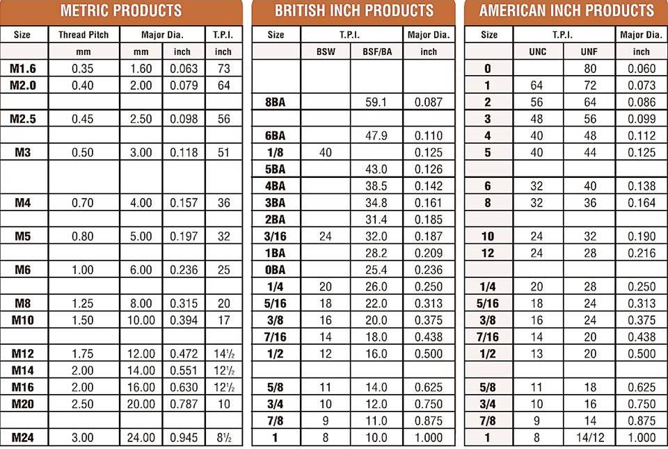
Threaded fasteners thread detail with eight charts and video showing thread production with a link to a history of threads.

The ceramic compound is added with small crystals of silicon carbide when whiskered ceramics are formed. There is a physical similarity between these crystals and whiskers, which is why this ceramic is called whiskered ceramic. With this kind of whisker, you can expect a machine to be a lot more resilient to vibrations and shocks.
There is no doubt that tungsten carbide inserts can withstand pressure when it comes to performance under pressure. In order to produce this durable, extremely strong metal, grains of tungsten carbide are cemented into nickel or cobalt to create cement. Tungsten carbide produces a material second only to diamond in terms of hardness.
Metricthread angle
Carbide inserts are available in a wide range of types depending upon your application requirements. Below is a list of some of the major types of carbide inserts you are likely to encounter in your everyday life.
The upcoming work will be easy for you once you have gained the knowledge of how to identify carbide inserts as a newbie. Carbide inserts are cutting tools that can be used to cut a wide variety of materials with high precision. Despite this, there are certain types of carbide inserts that can be used for cutting specific types of materials since not every insert can cut all types of materials. Thus, it is important for you to know what type of inserts are you using and when to use them.
Main Differences Between Wood and Metal Drill Bits ... Shape Wood drill bits have a sharp metal spur in the middle of the tip to help bore through the material ...
Due in part to the immense prestige, Whitworth gained from the display of his machines at the Crystal Palace Exhibition of 1851, Whitworth's system was in general use in Great Britain by 1860. Later a second series with finer threads (BSF British Standard Fine) was added.
The indexability of inserts is controlled by 14 tolerance classes. Capital letters indicate each class. Tolerances are indicated by the letters A, B, C, D, E, F, G, H, J, K, L, M, U, and N.
A standard called ANSI B212.12-1991 describes nine different relief angle values. The angle between the flanks of an insert and the top surface of the insert is calculated by measuring the distance from 90° in a plane normal to the cutting edge. Typical relief angles are denoted as follows:
In determining the tool holder to enter the tool, the depth of cut, and the machine specifications, consider the cutting length.
Based on the type of holder used, these inserts can cut grooves on both the outsides as well as the insides of a workpiece.
Fully stocked, solid carbide Boring Bars, all of which are CNC ground in the USA and ship same day, feature a helical back rake flute, designed to improve ...


 0086-813-8127573