
Milling Speed and Feed Calculator - rpm sfm calculator
ISOcarbideInsertchart
Pneumatic clamps attain their gripping force from the power created by a compressed gas (usually air). These systems are generally bulkier and are used for smaller workpieces that require less room on the worktable. Power clamping offers a few advantages over conventional clamping. First, these systems can be activated and deactivated quickly to save on changeover time. Second, they place uniform pressure on the part, which help prevent errors and deformation. A significant disadvantage they pose is the cost of a system but this can be quickly offset by production time saved.
Locating and supporting pieces should be made of a hardened material to prevent wear and allow for several uses without the workpieces they support falling out of tolerance. Supports and locators should also be standardized so that they can be easily replaced.
Supports do exactly what their name suggests, they support the workpiece during the machining process to avoid workpiece deformation. These components can double as locators and also come fixed, adjustable and integral, or assembled. Generally, supports are placed under the workpiece during manufacturing but this also depends on the geometry of the workpiece, the machine being operated and where the cutting tool will make contact. Supports can come in different shapes and sizes. For example, rest buttons are smaller support components used in series either from underneath the workpiece or from the sides. Concurrently, parallel supports are placed on either side of the part to provide general support.
First of all, let’s start by counting the number of cutting edges useful for our machining; the trigonal insert with its 6 cutting edges would be the master. The more cutting edges, the more pieces produced. Moreover, since the purchase cost of both inserts would be the same, the cost per cutting edge would be considerably in favour of the W-type insert; therefore, it will be cheaper per cutting edge. The W-type insert would definitely be the winner so far.
Tombstones: Large vertically oriented rectangular fixtures that orients a workpiece perpendicular to the worktable. Tombstones also have two sides to accommodate multiple parts.
A jig is a work holding device that holds, supports and locates a workpiece and guides the cutting tool into a specific operation (usually through the use of one or more bushings). A fixture is essentially the same type of device, but the main difference is that it does not guide the cutting tool into a specified operation. Fixtures are typically used in milling operations while jigs are generally used in drilling, reaming, tapping and boring. Jigs and fixtures are more precise relative to standard cnc workholding devices, which leads to tighter tolerances. They can also be indexable, allowing them to control the cutting tool movement as well as workpiece movement. Both jigs and fixtures are made up of the same basic components: fixture bodies, locators, supports, and clamps.
ISO insertchart
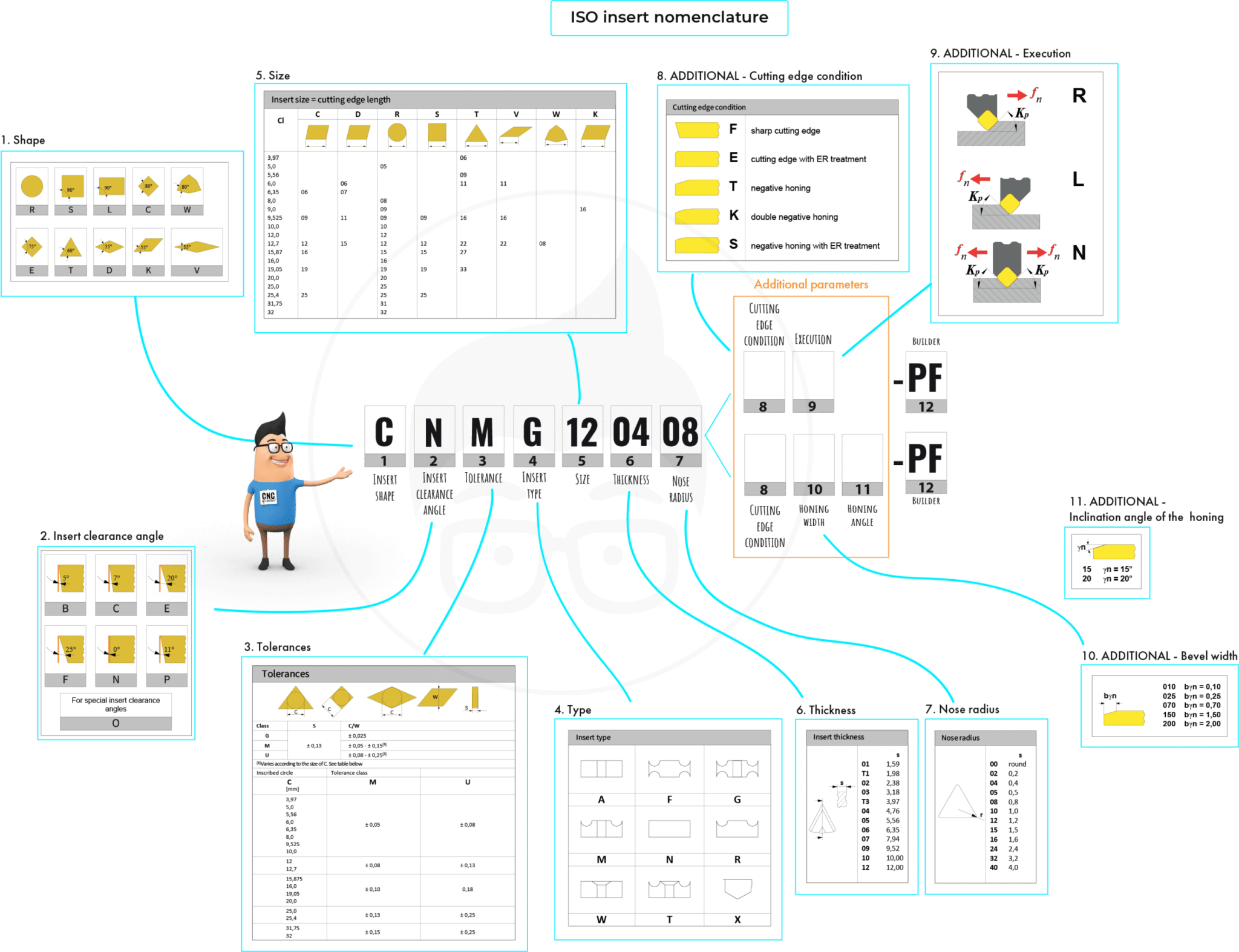
The first letter of the code is perhaps the most important one, that is the one that every turner must surely know because it defines the shape of the insert. In this lesson we have seen them all, although as we have said, in reality the most common shapes are as follows:
But does this way of thinking fit well with our chip volume and productivity? Is this really the most economical way? Of course, we would say yes if we stopped at this level. But we like to go into each topic in depth, so let’s think about it.
Millinginsertspecification
Look at how the inserts are mounted on their respective tools; we should notice that the W-shaped insert would offer a slot with a more open contact angle due to its shape.
Clamps should be placed above the locations of supports to allow the force of the clamp to pass into the support without deforming the workpiece. Clamps, locators and supports should also be placed to distribute cutting forces as evenly as possible throughout the part. The setup should allow for easy clamping and not require much change over time
Locators are characterized by four criteria: assembled, integral, fixed, and adjustable. Assembled locators, can be attached and removed from the fixture, which is contrary to integral locators that are built into the fixture. Fixed locators allow for no moving components, while adjustable locators permit movement through the use of threads and/or springs, and can adjust to a workpiece’s size. These can be combined to provide the appropriate rigidity-assembly convenience ratio. For example, a V-locator fixture is the combination of assembled and fixed locators. It can be secured to a fixture but has no moving components.
Because of its versatility and not only because of the number of operations it can perform but also because of the number of possible applications, from roughing to finishing, the C-type insert is undoubtedly the most widely sold and used insert in machine shops all over the world. It could be said that the C shape combined with its 95° lead angle has made the fortune not only of the insert manufacturers but also of us operators and workshop technicians, who have solved many problems with the use of this tool. In addition, the C shape placed on a different tool with a different lead angle would have a way of working with the so-called 100° recovery angle. In this way, the C-type insert would have 4 cutting edges instead of 2, making it one of the most affordable inserts.
Ideal workholding devices have easily repeatable setups. For this reason, some machines have standard workholding devices. Vises are generally used with milling machines while chucks or collets are used when running a lathe machine. Sometimes, a part may need a customized cnc workholding setup in order to secure the piece properly during machining. Fixtures and jigs are examples of customized devices.
ANSIinsert nomenclature
Faceplates: Typically used in lathe operations, where components are secured to the faceplate and then mounted onto the spindle.
Angle plates: Two plates perpendicular to each other but some are adjustable or customized to change the angle of the workpiece.
Sign up to receive a monthly recap of: – The latest machining solutions – Machining tips and tricks – A recap of our most popular posts
Used with recovery angles, it would certainly not be able to perform countless movements on the workpiece or remove large amounts of material. But within its field of application it would remain useful, also because the recovery angle assumes that the insert works at an angle between the cutting edges of 100°, so it is also very strong. This solution is successfully used in various sectors, for example when machining the surfaces of forged parts, roughing eccentric components where the interrupted cut affects the life of the insert. The first cut is often made in this way in order to improve and optimise production costs.
Machinists have a number of variables to consider when setting up devices for a machining operation. When it comes to cnc workholding, there are some major differences between holding a loosely toleranced duplicate part with a 10-minute cycle time and holding a tightly toleranced specialized part with a 10-hour cycle time. Determining which method works best for your machining job is essential to maintaining an efficient operation.
Carbideinsertidentification chart PDF
The C-type insert, on the other hand, has a much better positioning from this point of view, since two of its sides are all positioned in the insert slot. This aspect becomes important when we have to start using the inserts in roughing operations when depth of cut and feed rates are high. The fact of having better stability in the case of the C insert is a fundamental advantage for cutting edge life and machining success.
In our opinion, it should be used, for example, on machines where the working data are not so demanding. Its operations could be finishing and semi-finishing on materials that are not particularly difficult to machine.
Let’s take a closer look at some practical aspects of the C and W shape inserts. Let’s compare them on the assumption that they have the same nose radius, the same solid carbide grade and identical chipbreaker geometry.
Hydraulic Systems create a gripping force by attaining power from compressing a liquid. This type of power clamp is generally used with larger workpieces as it usually takes up less space relative to pneumatic clamps.
As a member of Harvey Performance Company’s New Product Development team, Robert strategized new products to introduce with each new catalog released by Harvey Performance Company’s collection of brands.
Turning insertIdentification chart
The design of the fixture or jigs should maximize the amount of operations that can be performed in one orientation. During the machining operation, the setup should be rigid and stable.
Workholding can be accomplished in a number of different ways and accomplish the same task of successfully gripping a part during a machining operation with the end result being in tolerance. The quality of this workholding may differ greatly as some setups will be more efficient than others. For example, there is no reason to create an elaborate jig for creating a small slot down the center of a rectangular brick of aluminum; a vise grip would work just fine. Maximizing the efficiency and effectiveness of an operators’ cnc workholding setup will boost productivity by saving on changeover, time as well as cost of scrapped, out of tolerance parts. print
Insert nomenclaturechart
C and W have different shapes – the first trigonal and the second rhomboidal – but both, once placed on the respective tool, tackle the machining with the same 95° tool cutting edge angle and therefore with a 5° lead angle. From the point of view of versatility, so the number of possible operations, both tools would be similar. Therefore they would be able to carry out the exact same machining operations for us operators: turning of various types, shouldering, chamfers and radius.
It is probable that the W-type insert will fail when heavily loaded due to the micro-vibrations created by the precarious fixing. Consequently, it is no longer so certain that we can use all 3 of its cutting edges, contrary to what happens with the C-shaped insert where we can certainly use both cutting edges.
ISO insert nomenclaturepdf
Clamps are devices used for strengthening or holding things together, and come in different shapes, sizes and strengths. Vises and chucks have movable jaws and are considered standard clamps. One atypical example is the toggle clamp, which has a pivot pin that acts as a fulcrum for a lever system. One of the more convenient types is a power clamping system. There are two type of power clamping methods: hydraulic and pneumatic.
www.harveytool.com www.helicaltool.com www.micro100.com www.titancuttingtools.com www.corehog.com www.valorholemaking.com
In today’s lesson we looked at the first part of the ISO insert nomenclature for mechanically fixed inserts. To be precise we looked at the first 4 letters.
Among the various shapes, we find exactly in the centre the C and W shapes. Both have an angle between the cutting edges of 80° and both, for one reason or another, are among the most popular.
First of all, I would like to remind you that you can download the scheme of the ISO insert nomenclature. Keep it handy during today’s lesson and the next one, by clicking on the icon at the bottom right of the video. It will also come in handy on the machine. ISO insert nomenclature In today’s lesson we looked at the first part of the ISO insert nomenclature for mechanically fixed inserts. To be precise we looked at the first 4 letters. The first letter of the code is perhaps the most important one, that is the one that every turner must surely know because it defines the shape of the insert. In this lesson we have seen them all, although as we have said, in reality the most common shapes are as follows: As we said in the lesson, the choice of shape influences the strength of the insert and its versatility in making profiles. Among the various shapes, we find exactly in the centre the C and W shapes. Both have an angle between the cutting edges of 80° and both, for one reason or another, are among the most popular. C and W in comparison Let’s take a closer look at some practical aspects of the C and W shape inserts. Let’s compare them on the assumption that they have the same nose radius, the same solid carbide grade and identical chipbreaker geometry. C and W have different shapes – the first trigonal and the second rhomboidal – but both, once placed on the respective tool, tackle the machining with the same 95° tool cutting edge angle and therefore with a 5° lead angle. From the point of view of versatility, so the number of possible operations, both tools would be similar. Therefore they would be able to carry out the exact same machining operations for us operators: turning of various types, shouldering, chamfers and radius. So which one are we going to use? First of all, let’s start by counting the number of cutting edges useful for our machining; the trigonal insert with its 6 cutting edges would be the master. The more cutting edges, the more pieces produced. Moreover, since the purchase cost of both inserts would be the same, the cost per cutting edge would be considerably in favour of the W-type insert; therefore, it will be cheaper per cutting edge. The W-type insert would definitely be the winner so far. But does this way of thinking fit well with our chip volume and productivity? Is this really the most economical way? Of course, we would say yes if we stopped at this level. But we like to go into each topic in depth, so let’s think about it. Look at how the inserts are mounted on their respective tools; we should notice that the W-shaped insert would offer a slot with a more open contact angle due to its shape. The C-type insert, on the other hand, has a much better positioning from this point of view, since two of its sides are all positioned in the insert slot. This aspect becomes important when we have to start using the inserts in roughing operations when depth of cut and feed rates are high. The fact of having better stability in the case of the C insert is a fundamental advantage for cutting edge life and machining success. It is probable that the W-type insert will fail when heavily loaded due to the micro-vibrations created by the precarious fixing. Consequently, it is no longer so certain that we can use all 3 of its cutting edges, contrary to what happens with the C-shaped insert where we can certainly use both cutting edges. In our opinion, it should be used, for example, on machines where the working data are not so demanding. Its operations could be finishing and semi-finishing on materials that are not particularly difficult to machine. Because of its versatility and not only because of the number of operations it can perform but also because of the number of possible applications, from roughing to finishing, the C-type insert is undoubtedly the most widely sold and used insert in machine shops all over the world. It could be said that the C shape combined with its 95° lead angle has made the fortune not only of the insert manufacturers but also of us operators and workshop technicians, who have solved many problems with the use of this tool. In addition, the C shape placed on a different tool with a different lead angle would have a way of working with the so-called 100° recovery angle. In this way, the C-type insert would have 4 cutting edges instead of 2, making it one of the most affordable inserts. Used with recovery angles, it would certainly not be able to perform countless movements on the workpiece or remove large amounts of material. But within its field of application it would remain useful, also because the recovery angle assumes that the insert works at an angle between the cutting edges of 100°, so it is also very strong. This solution is successfully used in various sectors, for example when machining the surfaces of forged parts, roughing eccentric components where the interrupted cut affects the life of the insert. The first cut is often made in this way in order to improve and optimise production costs.
First of all, I would like to remind you that you can download the scheme of the ISO insert nomenclature. Keep it handy during today’s lesson and the next one, by clicking on the icon at the bottom right of the video. It will also come in handy on the machine.
As we said in the lesson, the choice of shape influences the strength of the insert and its versatility in making profiles.


 0086-813-8127573