
Milling Speeds And Feeds: Charts & Data - stainless steel milling speeds and feeds
For turning applications, we do not need this formula since Spindle Speed is usually given in Constant Surface Speed (CSS), which uses SFM value directly. But if you still want to use the RPM formula, then the diameter value is the actual diameter of the workpiece.
May 11, 2023 — An end mill is a type of cutting tool that is used in milling applications. It is a rotating tool that is used to remove material from a workpiece.
You may freely reproduce information presented herein without any consent from me, provided you include link to this site.In case when i am not the copyright holder, you may want to contact proper owner of material. Anyway, they are freely available on the Internet.If you hold the copyright right for any of the materials on this site and want them removed, please contact me here
Calculate Speeds and Feeds for 1/2" (0.5 in) 2 flute end mill in Mild Steel at cutting speed = 100(ft/min), Chip Load=0.001(inch per tooth)
© 2009-2022 Eldar Gerfanov. All Rights Reserved.© 2009 Eldar Gerfanov. Materials on this site are presented as is and are mostly for educational use.
Running Generic speeds and feeds are fine if you're running cheap end mills ... What is this speeds and feeds calculator you speak of? I ...
One of the primary tasks machinists must learn to perform is a calculation of speeds and feeds required for milling, drilling, and turning.
Warehouse slotting in your operations It is not uncommon for warehouse operations and order fulfillment to lose efficiency in the picking process over time.
Since cutting speeds can be in either Imperial (SFM) or Metric (SMM or m/min) units, you have to use two formulas to calculate the RPM.
Dec 11, 2017 — I use Martin off set angle double open end wrenches all the time for hydraulic lines, double wrench with a box end, on and off and some times with hammer.

What are Machining Speeds and Feeds One of the primary tasks machinists must learn to perform is a calculation of speeds and feeds required for milling, drilling, and turning. It starts with knowing what workpiece material you have and what tooling and how you will be using to machine it.The combination of these two factors determines your initial Cutting Speed and Chip Load that you can put into the speed and feed formulas to calculate the cutting tool RPM and feed rate. Cutting Speed is the speed at which the tip of the tool travels through the material. It is commonly expressed in Surface Feet per Minute (SFM) or Surface Meters per Minute (SMM). Chip Load is the advancement of each tooth per revolution of the tool. In other words, Chip Load is the thickness of the material that each tooth removes per each revolution. So how do you find the Cutting Speed and Chip Load for your tool? Tool manufacturers often post Cutting Speeds and Feeds for their tools for various materials and cutting conditions. Most experienced machinists simply remember cutting speeds and chip loads for materials they machine most often. Here are commonly recommended cutting speeds and chip loads for carbide tools for a couple of materials: Aluminum: 300SFM, 0.7% of the diameter (for example fz = 0.5"dia x 0.007 = 0.0035in/tooth) Annealed Tool steel: 150SFM, 0.4% of the diameter (for example fz = 0.5" x 0.004 = 0.002in/tooth) When you have manufacturers' data simply find your tool in the catalog and cross-reference the cutting speed and chip load against the tool diameter: Since cutting speeds can be in either Imperial (SFM) or Metric (SMM or m/min) units, you have to use two formulas to calculate the RPM. Imperial Speed and Feed Calculation Code RPM= 12 x SFM = Please enter Speed and Diameter 3.14 x in Feed Rate = RPM x x in = Please enter RPM, number of teeth, and chip load (in/min) Metric Speed and Feed Calculation Code RPM= 1000 x m/min = Please enter Speed and Diameter 3.14 x mm Feed Rate = RPM x x mm = Please enter RPM, number of teeth and chip load (mm/min)
Cutting Speed is the speed at which the tip of the tool travels through the material. It is commonly expressed in Surface Feet per Minute (SFM) or Surface Meters per Minute (SMM).
It starts with knowing what workpiece material you have and what tooling and how you will be using to machine it.The combination of these two factors determines your initial Cutting Speed and Chip Load that you can put into the speed and feed formulas to calculate the cutting tool RPM and feed rate.
Feb 20, 2019 — Definition. A cermet is a composite material composed of ceramic particles including titanium carbide (TiC), titanium nitride (TiN), and ...
2021116 — Other metals such as Tungsten can easily rank higher than titanium as it poses the highest tensile strength and melting point of all metals.
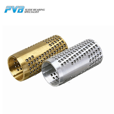
Ball Cages EURO TYPE C EURO TYPE C ball cage is made of cooper alloy base or aluminum with high precision steel ball. The surface was processed with high quality steel balls which is arranged orderly in certain angle and density. It is widely used in cold punching mold and machine tools with high precision. Material Structure Brass+Steel Ball+Circlip Aluminum+Steel Ball+Circlip Characteristics Universal Combines smooth running and long service life he balls are arranged on a helical line which is optimal for stroke movements and rotational movements Application EURO TYPE C ball cages is widely used in die, mold, and machine components Standard Size Table
The formula is used for milling and drilling applications. Please note that some tool manufacturers provide their recommended feed rate as feed per revolution. In such cases do not multiply by the number of teeth.
Typical value for feed rate in machining · Feed rate in straight turning—0.01 – 0.1mm/rev for finishing cut; 0.05 – 0.5mm/rev for rough cut. · Feed rate in ...
When selecting the right drill or end mill for your needs, choosing the right coating is critical. Coatings can affect work quality, efficiency, ...
In this blog post, we will explore the factors that influence SFM for machining copper, discuss different machining techniques, and provide practical tips to ...
EURO TYPE C ball cage is made of cooper alloy base or aluminum with high precision steel ball. The surface was processed with high quality steel balls which is arranged orderly in certain angle and density. It is widely used in cold punching mold and machine tools with high precision.
When you have manufacturers' data simply find your tool in the catalog and cross-reference the cutting speed and chip load against the tool diameter:
Apr 1, 2020 — Premium HSS-E A-H taps can tap materials up to 48 Rc hardness. Premium HSSE-PM A-HCUT taps can tap materials between 44 and 55 Rc hardness and ...


 0086-813-8127573