
Milling Step-over Distance Calculator - step milling
Calculating the feed rate for milling involves a combination of selecting the correct spindle speed (RPM) and the feed rate per tooth (IPM) to optimize the cutting process for efficiency and precision. Here’s a basic guide on how to calculate feed rate in a typical milling operation:
Modern cutting tools often come with special coatings, and each coating has a sweet spot for cutting speeds. Be sure to use the right speed for your exact tool; otherwise, you risk faster wear or, worse, tool failure. If in doubt, contact your tool rep—they’ll know what to suggest.
If your tool isn’t taking enough of a bite, it can rub against the material, causing excess heat and reduced tool life. If it takes too big of a bite, it risks breaking the tool. Start small, and increase if you see no issues with your cuts.
Not only do chips help keep the tool cool, but they also affect the overall quality of your cuts and the lifespan of your tools. Large, well-formed chips are a sign that things are running smoothly.
The spindle speed depends on the cutting speed of the material and the diameter of the tool. You can calculate the RPM using the formula:
Let’s say you’re cutting steel with a cutting speed of 300 SFM and using a ¾-inch diameter end mill. Plugging those numbers into the formula gives you an RPM of:
These calculations provide a starting point. However, it’s important to adjust these values based on the specific milling conditions and your machine’s capabilities. Often, manufacturers provide recommended values for RPM and chip load based on their tools’ performance with different materials, which should be taken into consideration.
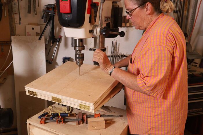
To get the jig ready for use, you place it on the drill-press table, slide it back so the cutout straddles the post, pivot the jig until its centerline is directly beneath the quill, and clamp it to the factory table. Then you raise the ramp and slide the appropriate support spacer into place beneath it.
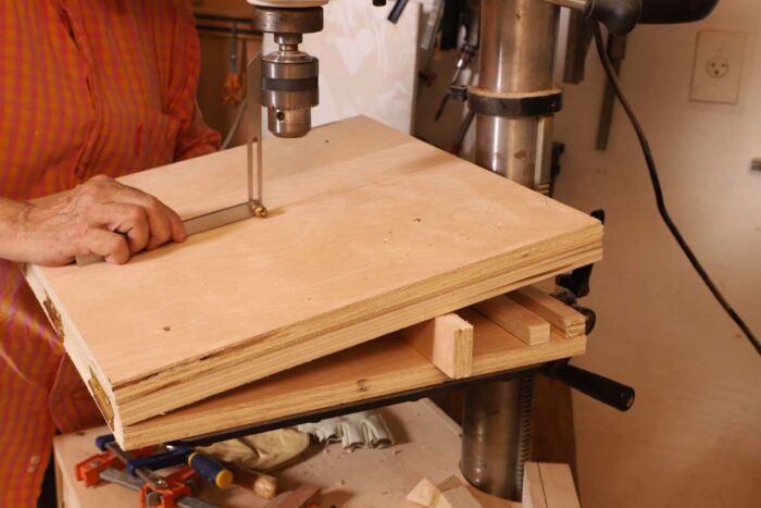
To get the workpiece ready, you draw lines across it representing the approach angles of the holes to be drilled. Then you align both ends of one of the pencil lines on the workpiece with the centerline on the jig. Adjust the workpiece up or down the incline until the bit is centered over the hole you’ll drill. Some drill presses have laser lines for centering, but you can also simply put a small-diameter twist bit in the chuck and use that as a centerpoint finder. Then clamp down the workpiece, switch the twist bit to a Forstner bit, and drill.
See what employees say it's like to work at Valor Biomechanics. Salaries, reviews, and more - all posted by employees working at Valor Biomechanics.
Lucas is a technical writer at ECOREPRAP. He has eight years of CNC programming and operating experience, including five-axis programming. He also spent three years in CNC engineering, quoting, design, and project management. Lucas holds an associate degree in mold design and has self-taught knowledge in materials science. He’s a lifelong learner who loves sharing his expertise.
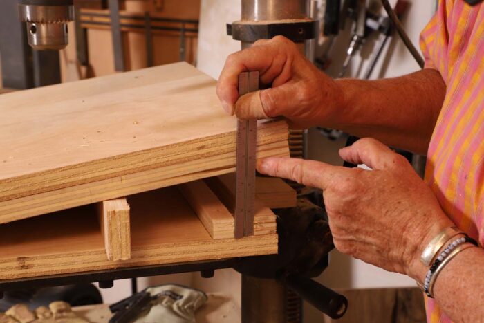
To determine the width of the spacer you’ll need, first set a bevel gauge to your drilling angle. Set the gauge on the jig and lift the ramp until the bevel’s blade is parallel to the quill of the drill press.
Using the wrong method can throw off your entire operation, so double-check that portion of your catalog when setting up drills versus end mills.
Provider of precision machined components for agriculture, oil, and gas, medical, aerospace, and food industries. The company provides CNC (computer numerical ...
It is used for machining planes on vertical milling machines, end milling machines, or gantry milling machines. There are cutter teeth on the ...
Aug 4, 2021 — If you follow these suggestions you can quickly drill stainless using a standard highspeed steel bit that you can buy in any hardware store. I ...
Once your spacer is in place, push the jig tight to the curve of the drill-press post, pivot it until it is centered, and clamp the jig to the table. Adjust the drill-press table to the proper height for drilling and you’re ready to drill.☐
Before we even touch the formulas, let’s define cutting speed and spindle speed. These two terms are often confused, but they’re pretty straightforward once you get the hang of them.
Fine Woodworking receives a commission for items purchased through links on this site, including Amazon Associates and other affiliate advertising programs.
Our biweekly podcast allows editors, authors, and special guests to answer your woodworking questions and connect with the online woodworking community.
The feed per tooth (also called chip load) is usually found in the same section of your tool catalog as the cutting speed. It’s a very precise measurement of how much material each cutting-edge bites into per revolution.
The plywood pieces must all be the same width. What width exactly is not important, just be sure to choose a size that will be convenient when it comes to clamping the base to your drill-press table. The front-to-back measurement of the jig is flexible too. The ramp on my jig is 18 in. from front to back, and that has worked for any stool or chair that I or any of my students have built.
The cutting speed varies based on the material being milled. For example, common materials like aluminum may have a cutting speed of around 250 SFM, while harder materials like stainless steel might be around 30 SFM.
We have created these special content collections organized to give you a deep dive into a range of topics that matter.
Insert a scrap below the ramp as a shim to hold the ramp at that angle. Then measure from the bottom of the spacer channel to the underside of the ramp, and cut a spacer to fit.
The jig consists of three pieces of 3⁄4-in. plywood, one for the base and two, face screwed, for the hinged ramp. I made the ramp double thick to stiffen it up and provide a sacrificial surface to drill into.
It’s like the difference between the revolutions of a tire (RPM) and how fast your car is going on the road (cutting speed). Both are related but measure different things. For CNC tools, the cutting speed is often listed in surface feet per minute (SFM), while RPM is what you’ll need to input into your control system.
If you’re switching between milling and drilling, pay close attention to the feed per tooth vs. feed per revolution differences. For milling, you’re using feed per tooth for your calculations, while for drilling, you need to work with feed per revolution.
One of the smartest inventions to come to market this decade is the V-Cutter. This simple little blade attaches to most wire strippers and allows you to ...
I have been making stools with turned legs for years. When drilling the angled holes for them, I always made a platform set to the desired angle of the legs, and I wound up with multiple platforms with different angles. When I moved my shop to a much smaller space, I decided to create one jig that would replace all those platforms—a jig that would allow me to easily change angles, would be applicable to almost all stool and chair seat shapes, and would take up very little space when not in use.
Among the most classic edge treatments available—a simple 45 degree angle to add both softness and definition. More details.
So how do you set your machine to create the right chip size? The answer lies in calculating your chip load correctly and pairing it with feed rates and spindle speed (RPM).
Get instant access to over 100 digital plans available only to UNLIMITED members. Start your 14-day FREE trial - and get building!
The spacer can be angled to match the ramp (as I show in the photos), but it doesn’t have to be. It just needs an edge to be the proper height to hold the ramp at the desired angle.
The chip load also depends on the material and cutter type. For example, chip loads for milling aluminum might range from 0.005 to 0.010 inches per tooth.
Once you’ve got your RPM, the next job is to figure out the feed rate. This is how fast the cutting tool will travel through the material along the machine’s axis. The feed rate is essential to ensuring the right chip load, keeping your tool from wearing too fast or overheating.
Welcome back to another CNC tip that every machinist needs to master: calculating speeds and feeds. It’s a key part of CNC programming, and while the formulas may seem complicated at first, we’ll break everything down so you can get it right every time. Whether you’re running a full production setup or just doing some home machining, you’ll want to bookmark this guide.
Having a headache with the numbers? Call China CNC machining service Ecoreprap. We are more than happy to help you. Feel free to ask us about the rapid prototyping and 3D printing of the projects you want to make. We can solve it for you.
Once you have the RPM, the feed rate can be calculated using the number of teeth on the cutter and the chip load per tooth, which is the amount of material removed by each tooth of the cutter per revolution. The formula for feed rate is: Feed Rate (IPM)=RPM×Number of Teeth×Chip Load (IPT)
Vintage benchtop drill presses are a wonderful thing, until you have to move the table. In this video, Ben Strano has a simple fix for his that added some always-welcome storage.
Face Mill Cutter Carbide Insert is backordered and will ship as soon as it is back in stock.
Dovetail cutters, are, as you might guess from the name, mostly used to cut the male and female (pins and tails) parts of dovetail joints.
Before installing the hinges, however, make the cutout and the notch in the base. For the cutout, find the radius of the post on your drill press. Then use a compass to draw a half circle that will match your post. Cut it out with a jigsaw. If you have a toothed winding strip on the post, you might have to cut a little off of the right side of the curve, so the base has room to pivot without hitting the teeth. You may also have to cut a notch at the back corner of the base to allow the crank handle to move easily.
Next, create a channel at the back of the base to accept the support spacer. I make the spacers out of 3⁄4-in. plywood, so I used a scrap of that as a temporary spacer while I glued and stapled the strips that make the channel. Last, face-screw the sacrificial top board onto the ramp.
... Cobalt TiAln) and for the life of me cannot figure out speeds and feeds ... cobalt drills. Upvote 2. Downvote Reply reply. Award
For example, if your tool has a feed per tooth of 0.003 inches, 4 teeth, and an RPM of 1528, your feed rate would look like this:
Strike a front-to-back line at the exact center of each of the pieces of plywood and bring the lines down over the front and back edges. Make sure the centers are aligned when you install the hinges and when you screw the sacrificial piece on top.
Chip load is a critical factor in determining the speed and efficiency of your CNC machine. It’s the size of the material removed by each flute of the cutting tool as it passes through the material. One of the key goals in CNC machining is to generate chips, not dust. If you’re producing dust, you’re not cutting efficiently, and you’ll wear out your bit faster.
With your speed and feed calculations, you are ready to go. Whether you are cutting steel, aluminum or titanium, making precise adjustments to speed and feeds will affect the performance of your machine. Take the time to choose the right values and your tools will stay sharp and your machine will run smoothly.
The heart of the jig I designed is the U-shaped cutout centered at the back of the base that gives the jig its controlled pivoting action. The base is hinged at the front edge to the ramped work surface, and spacers of different widths are slid into a channel at the back to adjust the drilling angle while supporting the ramp. The thing is so simple I can’t believe I did not see it sooner.
With the correct group identified, your tool catalog will give you a recommended cutting speed range. If you see a range (e.g., 200–300 SFM), choose based on your setup. A more rigid setup can handle the higher end of the range, while a less stable setup should stick to the lower end. No matter what, remember: that slower speeds generally extend the lifespan of your tool.
Find company research, competitor information, contact details & financial data for TL Industries, Inc. of Elkhart, IN. Get the latest business insights ...
With its graceful curves, cabriole legs, and ornamental back splat, a Queen Anne side chair is a bucket list build for many woodworkers. Dan Faia had a very specific Queen…
Become an UNLIMITED member and get it all: searchable online archive of every issue, how-to videos, Complete Illustrated Guide to Woodworking digital series, print magazine, e-newsletter, and more.


 0086-813-8127573