
MLCS Tapered Countersink Drill Bits with Stop Collars - tapered countersink bit
Lathe machine threadingformula
Aug 23, 2021 — I guess if you actually set out to do this with things you can order post-world war II you'd end up using a broaching tool instead. UPDATE ...
• Back (Top) Rake: The backward slope of the tool face away from the nose. This angle may be about 20 degrees and is provide for in the tool holder. Back rake permits the chips to flow away from the point of the cutting tool.
AN ILLEGAL XML CHARACTER hex-char WAS FOUND IN AN SQL/XML EXPRESSION OR FUNCTION ARGUMENT THAT BEGINS WITH STRING start-string.
• Side cutting edge angle: The angle which the cutting edge forms with the side of the tool shank. This angle may be from 10 to 20 degrees depending on the material being cut. If angle is over 30 degrees, the tool will tend to chatter.
RajkotLathe MachineThreadChartpdf Download
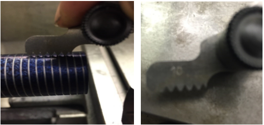
Thread cutting on the lathe is a process that produces a helical ridge of uniform section on the workpiece. This is performed by taking successive cuts with a threading toolbit the same shape as the thread form required.
1. For this practice exercise for threading, you will need a piece of round material, turned to an outside tread Diameter.
5. Grind the end cutting angle so that it form an angle a little less than 90 degrees with the side cutting edge. Hold the tool so that the end cutting edge angle and end end relief angle of 15 degrees are ground at the same time.
Lathe machine threading chartpdf free download
The properties that each of these materials possess are different and the application of each depends on the material being machined and the condition of the machine.
Rajkotlathe machinethreadchart
13. Feed the compound in .005 to .020 inch for the first pass using cutting oil. As you get near the final size, reduce the depth of cut to .001 to .002 inch.
Cutting tools used on a lathe are generally single pointed cutting tools and although the shape of the tool is changed for various applications. The same nomenclature applies to all cutting tools.
Oldlathe machine threading chart
Jul 31, 2024 — For most situations, cobalt is going to offer an intermediate option when compared to high speed steel and solid carbide options. The image ...
2. Hold the tool bit at the proper angle to grind the cutting edge angle. At the same, tilt the bottom of the tool bit in towards the wheel and grind 10 degrees side relief or clearance angle on the cutting edge. The cutting edge should be about .5 inches long and should be over about ¼ the width of the tool bit.
8. Move cross feed to the back tool off the work, move carriage to the end of the part and reset the cross feed to zero.
Aug 10, 2023 — This article aims to provide an in-depth understanding of slotting and its fundamental role in inventory management and fulfillment centers.
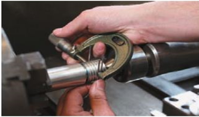
7. Move the threading tool up to the part using both the compound and the cross feed. Set the micrometer to zero on both dials.
• End cutting edge angle. The angle formed by the end cutting edge and a line at right angle to the centerline of the tool bit. This angle may be from 5 to 30 degrees depending on the type of cut and finish desired. For roughing cuts an angle of 5 to 15 degrees, angle between 15 and 30 degrees are used for general purpose turning tools. The larger angle permits the cutting tool to be swivelled to the left when taking light cuts close to the dog or chuck, or when turning to a shoulder.
Proper performance of a tool bit depends on the clearance and rake angles which must be ground on the tool bit. Although these angles vary for different materials, the nomenclature is the same for all tool bits.
2016105 — In pop culture, the movie and novel series "The Maze Runner" used the word "shank" in a different sense. In this context it means "someone who ...
20221117 — A carbide-tipped masonry drill bit is the best option for drilling angle iron. Ensure that the drill bit has an 80-degree sharpened tip. Using ...
• Side Rake Angle: The angle at which the face is ground away from the cutting edge. This angle may be 14 degrees for general purpose tool bits. Side rake centers a keener cutting edge and allows the chip to flow away quickly. For softer materials, the side rake angle is generally increased.
8. Grind a slight radius on the point of the cutting tool, being sure to maintain the same front and side clearance angle.
11. Take a scratch cut on the part without cutting fluid. Disengage the half nut at the end of the cut, stop the lathe and back out the tool using the cross feed. Return the carriage to the starting position.
Center and spotting drills are traditionally used to make a conical hole for a lathe center in order to make a starting point for a standard twist drill, ...
Concrete Finishing · Cutting · Demolition · Dewatering · Drain Cleaning · Drilling · Lighting · Threading. Batteries, Chargers & Power ...
MetricLathe Machine Threading Chartpdf
The workpiece is mounted to the headstock spindle in a chuck and the headstock spindle is locked after the workpiece is accurately setup. The hand reamer is mounted in an adjustable reamer wrench and supported with the tailstock center. As the wrench is revolved by hand, the hand reamer is fed into the hole simultaneously by turning the tailstock handwheel. Use plenty cutting fluid for reaming.
6. Nose radius: The radius to which the nose is ground. The size of the radius will affect the finish. For rough cut, a 1/16 inch nose radius used. For finish cut, a 1/16 to ⅛ inch nose radius is used.
Manufacturing Processes 4-5 Copyright © by LamNgeun Virasak is licensed under a Creative Commons Attribution 4.0 International License, except where otherwise noted.
• Side Relief (clearance) angle: The angle ground on the flank of the tool below the cutting edge. This angle may be from 6 to 10 degrees. The side clearance on a tool bit permit the cutting tool to advance lengthwise into the rotating work and prevent the flank from rubbing against the workpiece.
Metriclathe machine threading chart
Reamers are used to finish drilled holes or bores quickly and accurately to a specified sized hole and to produce a good surface finish. Reaming may be performed after a hole has been drilled or bored to within 0.005 to 0.015 inch of the finished size since the reamer is not designed to remove much material.
6 days ago — Response time may take up to 72 hours. If you are ... Go meet their pets. Tazewell Animal Protective Society, 100 TAPS Lane, Pekin, IL 61554
Jun 1, 2024 — Climb milling can put a greater strain on the tool due to the pulling force exerted by the rotating tool. This can lead to tool deflection and affect ...
2. Using either a parting tool or a specially ground tool, make an undercut for the tread equal to its single depth plus .005 inch.
3. While grinding tool bit, move the tool bit back and forth across the face of the grinding wheel. This accelerates grinding and prevents grooving the wheel.
The hole to be reamed with a machine reamer must be drilled or bored to within 0.010 inch of the finished size so that the machine reamer will only have to remove the cutter bit marks. Use plenty cutting fluid for reaming.
4. The tool bit must be cooled frequently during the grinding operation by dip into the water. Never overheat a tool bit.
Lathe machine threading chartpdf
• End Relief (clearance) angle: the angle ground below the nose of the tool bit which permits the cutting tool to be fed into the work. This angle may be 10 to 15 degrees for general purpose cut. This angle must be measured when the tool bit is held in the tool holder. The end relief angle varies with the hardness and type of material and type of cut being taken. The end relief angle is smaller for harder materials, to provide support under the cutting edge.
To cut a correct thread on the lathe, it is necessary first to make calculations so that the thread will have proper dimensions. The following diagrams and formulas will be helpful when calculating thread dimensions.


 0086-813-8127573