
nglos324 - workhardening - work hardening
RPMBritton sd
The carbide strips are recessed slightly down into the stainless steel for added protection. This way the strips will not be knocked off, or be under pressure when clamping a blade in the file guide. This also ensures there is less pressure on the carbide strip when clamping in a blade as they back onto a shoulder of steel.
For general purpose machining, use a recommended feed rate of .005 – .020 inches per revolution for roughing and a .002 – .004 inches per revolution for finishing.
rapid precision.ca
Subscribe to content that's 50% shop class, 50% feature film. Brian walks through building, wiring, tuning, and using the grinder; and regularly produces content on his other projects.
Aug 27, 2021 — BEST DRILL BITS FOR HARDENED STEEL OR STAINLESS STEEL: ... Cobalt drill bits are best suited for use on hard to machine metals, including hardened ...
Have you noticed that when you take a very small cut on the lathe .001 to .002 that the finish is usually poor, and that on the rough cut you made prior to this very light cut, the finish was good? The reason for this is: some tool pressure is desirable when making finish cuts.
Mar 9, 2022 — To get good quality holes in wood, it is important to choose the right drill bit for wood · In softwoods, spade bits are most effective. · The ...
The face is protected by two carbide strips, which only diamond or other exceptionally hard tools will scratch. These are 78 HRC and very hard but: ceramic belts can and will damage carbide. This tool is for use with hand tools, or normal aluminum oxide belts if using a grinder. The carbides are 3.9mm thick and can be replaced if required.
Speeds and feeds are the way to control the forces on the tool as it mills through a material. Ultimately, optimizing your speeds and feeds will result in ...
Example: Material = Aluminum 3” Cutter, 5 Teeth Chip Load = 0.018 per tooth RPM = 3000 IPS = 0.018 × 5 × 3000 = 270 Inches Per Minute
This is the first file guide in the world with screw-on carbides that cannot come off. We made it using stainless steel that will not rust, as well as being non-magnetic so steel dust won't stick to it as you grind. We think this is a good version of a file guide and you can now grind matching plunge lines, as well as get those really crisp blade to guard fit-ups with less hassle.
A lathe work cutting speed may be defined as the rate at which a point on the work circumference travels past the cutting tool. Cutting speed is always expressed in meters per minute (m/min) or in feet per minute (ft/min.) industry demands that machining operations be performed as quickly as possible; therefore current cutting speeds must be used for the type of material being cut. If a cutting speed is too high, the cutting tool edge breaks down rapidly, resulting in time lost recondition the tool. With too slow a cutting speed, time will be lost for the machining operation, resulting in low production rates. Based on research and testing by steel and cutting tool manufacturers, see lathe cutting speed table below. The cutting speeds for high speed steel listed below are recommended for efficient metal removal rates. These speeds may be varied slightly to shift factors such as the condition of the machine, the type of work material and sand or hard spots in the metal. The RPM at which the lathe should be set for cutting metals is as follows:
This power couple designed and prototyped by Bjorn of Nordic edge is the new standard in achieving consistent, repeatable results.
Whenever possible, only two cut should be taken to bring a diameter cut. Since the purpose of a rough cut is to remove excess material quickly and surface finish is not too important. A coarse feed should be used. The finishing cut is used to bring the diameter to size and produce a good surface finish and therefore a fine feed should be used.
It has been my experience to take at least three cuts. One to remove excess material quickly: the rough cut, one cut to establish finish and to allow for tool pressure, and one to finish the cut.
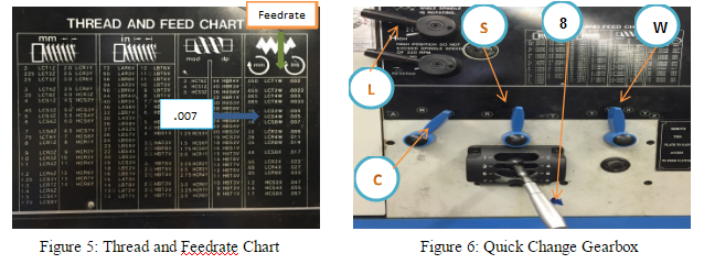
The feed of on lathe, or the distance the carriage will travel in on revolution of the spindle, depends on the speed of the feed rod or lead screw. This is controlled by the change gears in the quick-change gearbox. This quick change gearbox obtains its drive from the head stock spindle through the end gear train. A feeds and thread chart mounted on the front of the quick-change gearbox indicates the various feeds and metric pitches or thread per inch which may be obtained by setting levers to the positions indicated.
To offset these problems, the carbide cutting tip itself is often in the form of a small insert for a larger tipped tool whose shank is made of another material ...
Dremel 911 7/16 In. (11.1 mm) Aluminum Oxide Grinding Stone.
This pro tool will give you nothing but consistent, repeatable results. Easily adjust & lock in your angle, and knock out perfectly matching bevels and plunge lines.
Shop eBay for great deals on Carbide Insert Boring Bar Insert Industrial Indexable Inserts. You'll find new or used products in Carbide Insert Boring Bar ...
Promotions, new products and sales – directly to your inbox. Don't worry, we don't spam. Your info is protected and will never ever be shared with any 3rd party.
The Carbide File Guide is solid stainless steel, and will not rust when dunked in water during grinding as you keep the blade cool. Metal dust will not stick to this non-magnetic steel.
Text Twist Solver Word Finder unscrambled the words from letters, ETSHOW. 102 words & anagrams were found by unscrambling ETSHOW.
6. As the softness of the material decreases, the cutting speed increases. Additionally, as the cutting tool material becomes stronger, the cutting speed increases.
Tap Drill Sizes for Thread Forming Taps. Cold Forming Taps for Internal ... 40. 5. 1.825. 1.85mm. 3. 1.802. 1.8mm. M2.5x.45. 6. 2.319. 2.35mm. 3. 2.277. 2.3mm.
The leader in performance motorcycle parts for Harley-Davidson® motorcycles and the powersports industry.
Keep up with the House team's daily projects and random mail calls in the workshop. This is where you'll find behind the scenes content and get early access to promo codes & giveaways.
rapidprecision.net
Your order will ship USPS Priority within 3 business days. Shipping turnaround may extend to 4-5 business days during peak/holiday weeks.
4. What would the RPM be if we were turning a 1.00” diameter workpiece made out of mild steel, using Carbide cutting tool?
The lathes are designed to operate at various spindle speeds for machining of different materials. There speeds are measured in RPM (revolutions per minute) and are changed by the cone pulleys or gear levels. One a belt-driven lathe, various speeds are obtained by changing the flat belt and the back gear drive. One the geared-head lathe speeds are changed by moving the speed levers into proper positions according to the RPM chart fastened to the lathe machine (mostly on headstock). While shifting the lever positions, place one hand on the faceplate or chuck, and form the face plate slowly by hand. This will enable the levers for engage the gear teeth without clashing. Never change speeds when the lathe is running on lathers equipped with variable speed drivers, the speed is changed by turning a dial of handle while he machine is running.
The idea itself was good, I just thought we could come up with a better version. After a lot of work and prototyping, we came up with the Nordic Edge file guide.
Manufacturing Processes 4-5 Copyright © by LamNgeun Virasak is licensed under a Creative Commons Attribution 4.0 International License, except where otherwise noted.
This bevel jig is designed for use with a file guide, so there is no stopper bolt supporting the blade spine. If you're using this without a file guide, clamp the blade securely to the bevel jig with 2 G-clamps or similar. It is 150mm wide with two slots for the Carbide Faced File Guide (not included).
7.W = Select Feed Ranges and change to W on this lever (See Figure 3) Before turning on the lathe, be sure all levers are fully engaged by turning the headstock spindle by hand, and see that the feed rod turns.
RPMManufacturing
In order to eliminate this time loss, we can, and should, use recommended metal-removal rates that have been researched and tested by steel and cutting-tool manufactures. We can find these cutting speeds and metal removal rates in our appendix or in the Machinery’s Handbook.
The recommended feeds for cutting various materials when using a high speed steel cutting tools listed in table below. For general purpose machining a .005 – .020 inch feed for roughing and a .012 to .004 inch feed for finishing is recommended.
We can control the feed on an engine lathe by using the change gears in the quick-change gearbox. Our textbook recommends whenever possible, only two cuts should be taken to bring a diameter to size: a roughing cut and a finishing cut.
Shop Thread Forming Tap: #4-40 UNC, 2B Class of Fit, Bottoming, High Speed Steel, Bright Finish at MSC Direct top provider of high quality products.
The success of our DIY Grinders group is proof that collaboration is king. So we just launched one for forges -- this is your friendly space to learn and share ideas with us and the "hive mind".
The feed of a lathe is the distance the cutting tool advances along the length of the work for every revolution of the spindle. For example, if the lathe is set for a .020 inch feed, the cutting tool will travel the length of the work .020 inch for every complete turn that work makes. The feed of a lathe is dependent upon the speed of the lead screw or feed rod. The speed is controlled by the change gears in the quick change gearbox.
To operate any machine efficiently, the machinist must learn the importance of cutting speeds and feeds. A lot of time can be lost if the machines are not set at the proper speed and feeds for the workpiece.
5. Roughing cuts (0.01 in. to 0.03 in. depth of cut) for most aluminum alloys run at a feedrate of .005 inches per minute (IPM) to 0.02 IPM while finishing cuts (0.002 in. to 0.012 in. depth of cut) run at 0.002 IPM to 0.004 IPM.
4. Feed rate and cutting speed are mostly determined by the material that’s being cut. In addition, the deepness of the cut, size and condition of the lathe, and rigidity of the lathe should still be considered.
This file guide will enable you to precision-file both sides of the blade dead-even, using files or your grinder. The benefits are blade bevels starting perfectly even, and stick tang shoulders being dead square and even for perfect bolster fit.
If you were cutting thread all day long: day in and day out. You might set the lathe up for only two cuts. One cut to remove all but .002 or .003 of material and the last cut to hold size and finish. This is done all the time in some shops today.


 0086-813-8127573