
NOAA Chart 11480: Charleston Light to Cape Canaveral - 11480
How to cutan objectinhalfin Fusion 360
Jun 9, 2021 — Drilling is the process of penetrating through the ground and extracting rocks from various depths beneath the surface for confirming the geology beneath.
CVE-2021-27347. Publication date 10 June 2021. Last updated 24 July 2024. Ubuntu priority. Medium. Why this priority? Cvss 3 Severity Score. 5.5 · Medium.
... INFO. End Mills. End Mill SizesSpeeds And Feeds ChartsSpeeds And Feeds Calculator. Burs. BLOGCONTACT. ▷ Search for Products. New Account | Login. fake ...
Fusion 360 cutbody with another body
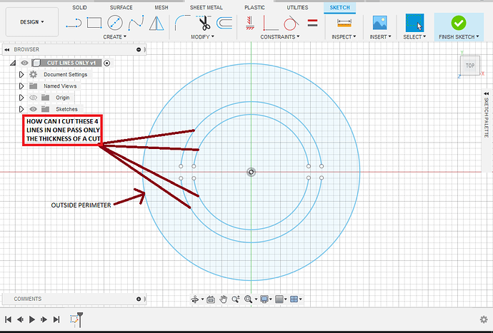
Trying to figure out how to make a single pass cut in Fusion360. Every time I extrude in the pic attached it will not extrude the lines only the outside perimeter… Any advice? see attached Untitled1022×693 103 KB
I have a video on here of doing exactly that I’m not at my computer right now or I would link it but if you search “loom” in the magnifying glass up above there was a video where I was helping someone with a telephone image that had some single line cutting involved but also a body.
Fusion 360split body for printing
IAMTHEONEWHOKNOCKS.dxf (211.6 KB) Iamtheonewhoknocks.nc (205.1 KB) (edit : switched operation order ) this cut file is at 50 ipm but with the incorrect kerf it likely will turn out odd.
The Picatinny rail, also known as a MIL-STD-1913 rail, is a military standard rail system that provides a mounting platform for firearm accessories.
202263 — Second Letter Stand for Relief Angle of Insert · C Means 7 Degrees – D means 15 Degree – N Means 0 Degree (see Chart Below) · N is also called ...
Company Profile at Drillpoint Resources · Experience: Drillpoint Resources · Location: Fort Worth · 90 connections on LinkedIn. View Drillpoint Resources' ...
DNMG-331-PM 55 Degree Negative Rake Coated Carbide Insert I.C. is 3/8". L is 29/64". S is 3/16". d is 0.15". r is .0157". ISO insert number is DNMG110404PM.
There is a type of extrude that will “extrude” a line but with this type of extrusion does not become a three-dimensional body it becomes a two-dimensional surface.
Fusion 360 cutbody with sketch
If you need anything else send me a message. I’ll be home ain’t going nowhere got the covid figured I’d try to work on this while I feel like crap and stuck in the house. Thanks for the help. Really need to learn how to do this thing with the lines…
How to cuta sketchin Fusion 360
This information is not intended as an offer to sell, or the solicitation of an offer to buy, a franchise. It is for information purposes only. An offer is made only by Franchise Disclosure Document (FDD). Currently, the following states regulate the offer and sale of franchises: California, Hawaii, Illinois, Indiana, Maryland, Michigan, Minnesota, New York, North Dakota, Oregon, Rhode Island, South Dakota, Virginia, Washington, and Wisconsin. If you are a resident of, or wish to acquire a franchise for a Matco Tools distributorship to be located in, one of these states or a country whose laws regulate the offer and sale of franchises, we will not offer you a franchise unless and until we have complied with applicable pre-sale registration and disclosure requirements in your jurisdiction.
Fusion 360 cutbody with plane
Get Canada Nickel Company Inc (CNC-V:Canadian Ventures Exchange) real-time stock quotes, news, price and financial information from CNBC.
How to cuta square holein Fusion 360
The reason for this is extrusion takes a two-dimensional profile and makes it a three-dimensional body where a line is one dimensional piece of geometry and extruding it would only make it a two-dimensional surface.
I would normally use a body for the outer cut geometry and all the inner cuts I would use the sketch geometry to create tool paths.
Screenshot_20220126-1713471020×1820 91.2 KB The line weight of the tool path doesn’t properly represent the kerf width of the tool in these shots. But it is a complete tool path and it will attempt to cut that geometry at 14 and 1/2 in.
Sep 28, 2024 — Often it's challenging to find a single open-source data catalog tool that is capable of addressing all challenges your data team faces. We ...
@TinWhisperer I got that drawing to work, unfortunately that is just something I drew up to get an idea how it works. The drawing I am actually working on is not cooperating for me and I can’t figure out why… followed your video in the other post the same way I did the one above… don’t get it tried multiple time with no luck… Here is the one I am working on attached BBSIGN v1.f3d (222.0 KB)
Extruded .125 mild Steel I use 0 side and top offset Everything under feed at 50 inches per minute Select always inside Tolerance .0004 Sideways comp left Compensation type in computer Finishing overlap 0 Outer corner mode roll around corners Preserve order yes Talked to leave zero Smoothing zero Feed optimization zero Nozzle down yes stay down distance 24 in Cut stock clearance .015 Force retract for inside cut no Stay down feed rate 50 in Leading entry checked lead in radius 0 Lead in sweep angle 90 Leading distance zero Lead out exit no Pierce clearance .015
How toextrudecut in Fusion 360
May 26, 2022 — Probably not much, inserts for stainless tend to have a sharper edge and more positive edge geometry. Often you will find the inserts dual ...
I also had to do it in two operations there’s just too much complex geometry that needs to have cutting on one side and then if you try to line cut on top of that that needs to be cut on center it just becomes messy. Possible but messy.
Thank you again, I will hopefully get some time to work on it this weekend. I know it’s tight but I have cut things like this before with success. I got the tool path to generate on the face, just could not get it to allow me to do the thin lines and lettering. Hopefully this will work for me much appreciated obviously a guru you are… Thanks again!


 0086-813-8127573