
Now carrying Olson Manufacturing Putters! - olson putter company
Once cooled, the column shaft was clamped into the vise of a Bridgeport mill. The end result (following several attempts—all with more annealing) was a small dent in the hardened shift lever using a 1/8-inch bit. That ‘dent’ measured approximately 0.010-inch deep. It wasn’t looking good.
Hence, feed rate and cutting speed parameters are paramount to machining operations. Feeds and speeds differ in machining because cutting speed produces the generatrix while the feed rate produces the directrix.
Although the same factors affect the cutting speed and feed rate, their effects are less pronounced. The feed rate is paramount to the final aesthetic appeal of the finished parts. Thus, feed rate optimization is critical in CNC machining processes.
Deep bow to this advice. Unfortunately, I went through the same struggles as this gentlemen, trying to drill a broken tap into a hole. The granite drill bit mounted on a Dremel went through the tap like butter.
Feed rateformula formilling
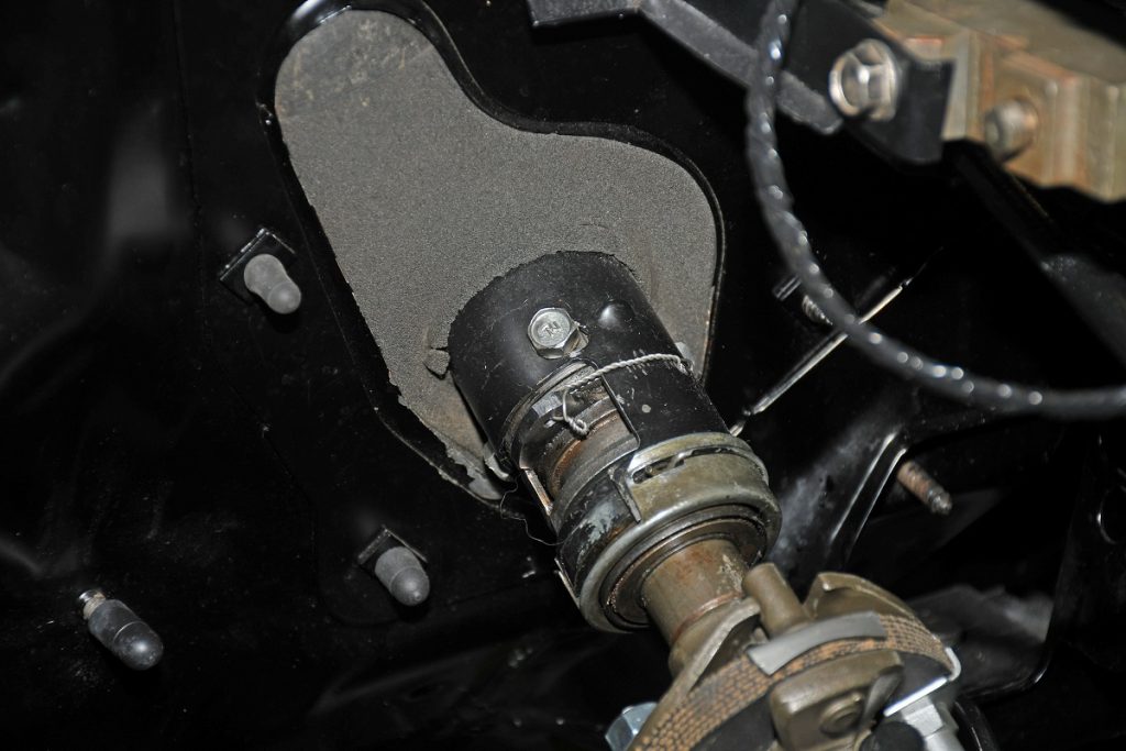
I needed to drill a hole through hardened steel—in this case, the piece of steel was what was left of the lower shift lever on a steering column.
Millingformulas PDF
The cutting tool compresses the surface of the workpiece when machining and shears a thin layer of material as a chip. The relative velocity between the CNC tool and the workpiece is required to transfer the intended compressive force. The cutting velocity produces the primary relative velocity, which helps envisage the material removal.
Aside from the feed rate, the cutting tool geometry can affect a machined part’s surface finish. If the geometry permits, a higher value for the tool geometry would be advisable. CNC tools with more cutting edges shear less material per pass. Hence, they can handle higher feed rates. As such, ensure the tool’s geometry is utilized to attain an optimal feed rate.
Another factor determining optimal cutting speeds is how long the machinist wants the CNC cutting tool to last. This often includes evaluating variables like the tool’s cost and cost compared to the quantity of parts fabricated. While higher cutting speeds might be feasible for use, provided these variables are favorable, softer cutting tool materials will lead to premature tool wear.
Ensuring optimum rotational speed in CNC machining processes is essential to attain the best results. However, it is feasible to determine the optimum cutting speed for a specific CNC machining process by examining other factors. These factors may include:
Worked great on my cast iron piece. Had no luck w titanium or conventional carbide tipped bits that I tried and broke or dulled. Even tried Dremel with diamond cutting tips to no avail. The stone/tile worked great, following the drill bit mfr instructions to use hammer drill at high, not low, speed- which was totally different than what I’ve read widely. Thank you so much for this valuable tip.
Typical CNC machine tools possess a feed-by-feed rod within the minimum and maximum feed rate limits. Beyond the limit is impermissible for these machine tools, and only limited feed rate options within the permissible limit can be applied for conventional lathe machines. As such, maintain the permissible feed rate based on the machine’s capability and as the tool manufacturer specifies.
CNC machining, a popular subtractive manufacturing process, utilizes programmed codes, such as G-, F-, S- and M-codes, to control machine functions. These programmed command codes dictate necessary cutting parameters such as cutting tool movement, RPMs, feed rates, and spindle speed.
Therefore, the machinists would have to run the tool with the available machine’s maximum speed while maintaining the required chip load for the diameter. Consequently, you can achieve optimal parameters at the machine’s top speed.
Higher feed rates result in high cutting force and high vibrations experienced during machining. Each CNC machine tool has operational limits and capabilities based on its rigidity, power, and torque. Hence, it would be best to choose the feed rate based on the absorption and transmission of high forces and vibration of the machine tool.
Tablefeedformula
The feed rate generally involves a linear motion (i.e., the distance covered in a line). However, there are certain situations when the feed rates are regarded as being in an arc or circular interpolation path (inner or outer diameter). There is an increase in the angle of engagement on a tool, which results in a non-linear path as the depth of the cut increases. The tool’s engagement is higher for internal corners than external corners.
Despite being intertwined in machining operations, feed rate, and cutting speed are two distinct motions in CNC machining. Here are some key differences between these parameters:
The steering column was a three-on-the-tree assembly converted to a floor shift application with a new bowl, but parts of the shifter linkage remained. The idea here was to trim the remnants off and then drill a hole in what was left so that it could be safety-wired shut.
Thank you sir for your effort to make this blog. I went to HD and got some carbide tip masonry bits for stone and glass and though they don’t last more than four cuts each, if you get the four pack of 1/8″- 5/16″ you can stretch the life of each bit to get around four full 5/16″ holes in 1/4″ hardened steel ‘T’ Rails . Four 5/8″ holes makes one full corner of a Deer Fence. This was a prayer come true for me, literally. God bless.
The primary objective of machining operations is to maximize the material removal rate without sacrificing tool life and the quality of finished parts. However, there are cases where you can increase the feed rate for higher productivity and cycle time at the expense of superior surface quality. Nevertheless, you can maintain a balanced speed and feed rate to achieve cost-effective production.
From AT-Machining, I’m a CNC Machining Expert in this field for more than 20 years. We offer cost-effective machining services from China. Ask for a quote for your ongoing or upcoming projects now!
Depending on the raw material, you must consider the milling tool diameter and surface feet per minute (SFM) to determine the cutter speed in RPM. However, the calculated speed may be unfeasible, especially with smaller tooling and certain materials.
Worked like a charm. Nothing made a dent in the hardened galvanised steel. I had to drill 22 holes and still going strong.
The way the feed rate and cutting speed influence cutting temperature is another essential difference between these parameters. The workpiece and cutting tools can be damaged when exposed to excess heat during CNC machining.
You have to follow two methods to achieve the final feed – the first method is to determine the feed per tooth, while the second method involves determining the feed rate of the tool using the feed per tooth.
Millingspeeds and feeds Chart
Another synchronous motion (feed motion) must be provided to the CNC tool or workpiece along the required direction to envisage the material removed from the total workpiece surface. The feed rate, cutting tools’ simultaneous actions, and feed rate will fulfill the basic requirements of the machining process.
The cutting speed substantially impacts the cutting temperature because higher cutting speeds lead to increased temperatures, while slower cutting speeds ensure moderate temperatures. Conversely, the feed rate possesses a comparatively lower impact on the cutting temperature and CNC tool life.
Generally, an increase in feed rate for all cutting speeds and depths of cut causes an increase in cutting force. Besides, cutting force increases as the tool wears since a worn cutting tool has less efficient teeth (cutting edge). Hence, it would be best to mitigate excessive tool wear and adjust feed accordingly to ensure consistent cutting force and extended tool life.
The tool material (Cermet, Ceramic, HSS cutting tool, etc.), the blank material (Stainless Steel, Mild Steel, Aluminum, Wood, etc.), and other cutting parameters like CNC machine characteristics and surface finish will determine feed rate variation. The feed rate determines the machined product’s physical appeal; hence, the feed rate’s optimization is essential in CNC machining processes. Machinists calculate the feed rate by considering the number of flutes or teeth on a CNC cutter and calculating each tooth’s feed rate.
Cut width or radial depth of cut (RDOC) is the span along the surface of the workpiece that the CNC tool engages in a single pass. Typically, chip thinning occurs when any cut width is less than half the diameter. It is a common manufacturing defect where there is a reduced chip load or material the cutter removes in one revolution. Since chip thinning could result in extended lead time, it is essential to prevent it. Besides, increasing the feed rate will help mitigate the effects of chip thinning, increase productivity, and extend the tool’s lifespan. However, you can adopt a higher cutting speed to resolve chip thinning.
I searched the internet for answers. I found a bulletin board post where someone said a masonry drill bit would work perfectly for my dilemma. I bought a masonry bit. Unfortunately, that didn’t work either.
[…] Drill bit hunt for hardened steel work: https://www.onallcylinders.com/2020/01/31/hunting-for-a-drill-bit-to-drill-through-hardened-steel/ […]
Wayne Scraba is a diehard car guy and regular contributor to OnAllCylinders. He’s owned his own speed shop, built race cars, street rods, and custom motorcycles, and restored muscle cars. He’s authored five how-to books and written over 4,500 tech articles that have appeared in sixty different high performance automotive, motorcycle and aviation magazines worldwide.
Feed rate and cutting speed are paramount variables in optimizing the efficiency and quality of your CNC machining process. Comprehending these parameters helps machinists adjust them to attain optimized tool longevity, desired surface finish on machined parts, improved productivity, and overall CNC machining results. When it comes to CNC machine speed and feed rate optimization, there is no one-size-fits-all. Thus, variables such as depth of cut, surface finish, tool material, expected tool life, and workpiece material type determine the ideal configuration.
How about that! This worked for me. I had a sprocket I needed to open the rollpin size up to 3/16. None of my carbide or titanium bits would touch it.
He dragged a file across the linkage and quickly came to the conclusion that the steel was actually hardened (and not so much by me). Next, he annealed it with a TIG welder.
All of the screws on my ar15 are hardened steel and the torque screws wont come out I’m gonna try this and hopefully it works. Thankyou
Thank you! This is the info I was looking for after having unsuccessfully tried to cut through hardened carbon steel in every possible way. I also tried a plasma cutter on very low current in order to punch that damn hole, or at least the beginning of it, but no way – even a slightest steel residual in the hole basically makes it impossible to drill through it with every bit I own. I will try the granite bit for sure.
Finally, while rummaging through various drill bits at Home Depot, I spied a goofy-looking one with no flutes that is designed to drill through granite tile.
Found this post while researching drill bits that will go through metal. I had an experience like this yesterday. Tried every bit I had to no avail. Then I found this bit we used to drill through ceramic tile. It was really beat up and looked horrible but I tried anyway and it did the trick. Went where no bit had gone before. I need a new one because I have a lot more holes to drill and I messed that bit up drilling through the tile.
This guide explores an in-depth comparison of feed rate and cutting speed in CNC machines. Continue reading to learn their key differences and their critical roles in optimizing your CNC process to achieve optimal results!
Feed rateformula for turning
Even though this process is computer-controlled, the machinist must consider these variables when designing products for CNC machining processes. Feed rate and cutting speed help optimize different aspects of the CNC machining process. While the cutting speed optimizes the power consumption and cutting tool’s life, the feed rate controls the surface roughness of the finished products and the machining time.
You never tried the M42 8% cobalt drill bits ? This is the industrial standard for drilling hard steel. https://drillsandcutters.com/1-60-cobalt-steel-jobber-drill-set-60-pieces/?gclid=Cj0KCQiA4NTxBRDxARIsAHyp6gAVLrm4xT-K5i72Yj6M1rDntyFbCPrCl_pk-LA5LepPAb_2X7wN3JAaAtGIEALw_wcB
Machinists use various lathe tools for different CNC machining. Each tool has different hardness properties since they are created from varying material types. The cutting speed used in the CNC machining process will significantly affect the cutting tool material. The machinist can use a high cutting speed with slight effects if the cutting material possesses high strength. However, softer cutting tool materials will likely wear out quickly with higher cutting speeds, leading to shorter tool life.
I knew going in that by cutting (with a cut-off wheel) and grinding the linkage it would work harden. That didn’t seem to be too big of a problem because I could anneal it after trimming it to shape.
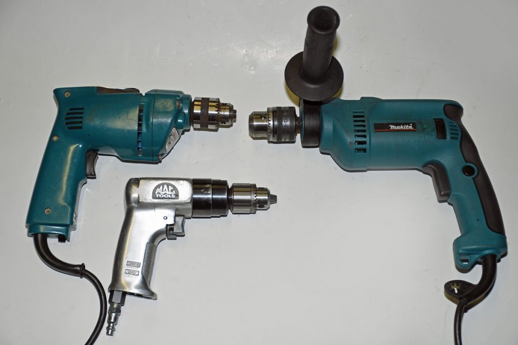
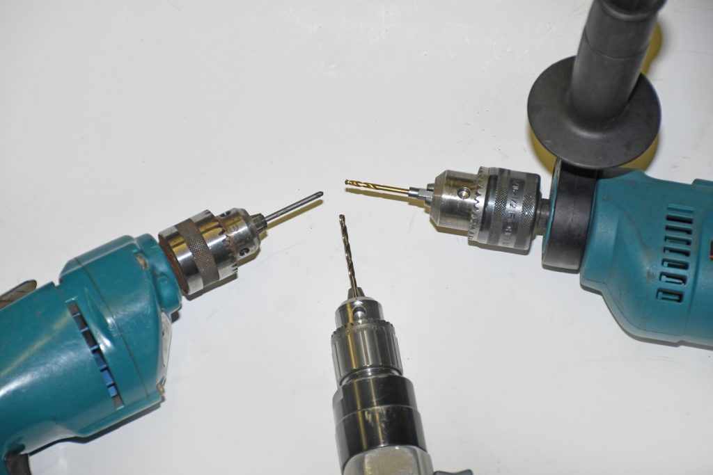
In the process, I tried pretty much everything in my tool chests. I tried to drill the hole with three different drills—a conventional 3/8-inch Makita variable-speed electric, a Mac Tools air-powered drill, and a ½-inch Makita hammer drill.
Cutting or surface speed is generally measured in ft/min (feet per minute) or m/min(meters per minute). Cutting speed is critical in determining other CNC machining parameters, including power consumption, cutting temperature tool life, etc. The values of cutting speeds of a milling machine vary based on different materials, including plastics, low-carbon steel, high-carbon steel, and aluminum. Machinists must operate other machine tools, such as knurling and threading tools, and lower cutting speed.
I highly recommend you try one if you have to drill through hardened steel. For a closer look at the drill bit selection I went through in the process, check out the accompanying photos.
Cutting speed formula
Feeding the material too slowly during CNC machining can cause rubbing instead of cutting, resulting in a poor tool life. Conversely, an extremely high feed rate or higher speed than the maximum RPM results in overheating or cutter breakage due to the excessive friction generated during machining. As such, it is essential to maintain optimal feed rates during various machining operations for the best tool life and surface roughness.
The feed rate is the distance a cutting tool covers during one spindle in revolution or the velocity at which the workpiece advances the milling cutter or vice versa. It can also be called the cutting tool engagement speed for milling operations. Machinists often measure it in millimeters/minute or inches/minute (mpm or ipm). Feed rate can be measured in millimeters/revolution or inches/revolution (mpr or ipr) for boring or turning operations.
Since I had a hammer drill, I figured I had nothing to lose. I was certain this would work. The guy at the tool supply shop agreed. After all, a hammer drill provides plenty of grunt. I bought and tried the fancy hammer drill bit. And it didn’t do any better than the others. Obviously, brute force wasn’t going to work either.
A crucial factor known as cutting temperature determines the differences between the feed rate and cutting speed. Higher cutting temperatures can adversely affect parameters, including surface roughness and tool life. However, since there is an extensive margin for error, the effects of speeds and feeds are not visible on softer materials such as aluminum or resin. Nevertheless, the poor effects of speeds and feeds are noticeable on harder materials like Inconel and titanium due to the limited error range.
Cutting force is a crucial determinant of a finished part’s quality. Hence, excessive cutting force can result in tool chatter, deflection, and vibration, adversely affecting the overall quality of the fabricated products, surface finish, and dimensional accuracy.
To attain a superior surface finish, it is advisable to employ lower feed rates for workpiece finishing while you consider a coarse feed rate for the rough cut. For instance, you can adopt 0.01 to 0.05 mm/rev for finishing operations and 0.1 to 0.3 mm/rev for roughing operations. Hence, the required surface roughness is calculated, and the feed rate is calibrated to meet the specifications.
Feedper tooth formula
Rapid tool breakage usually occurs due to slight differences between the feed rate and speed. Therefore, the feed rate and speeds are mandatory to achieve superior surface roughness on machined parts. The chatter marks will appear on the machined surface if the machine runs at a high spindle speeds and tool rate.
I would’ve thought of cobalt bits and a drill press first. Never thought about how hard tile is though. I’ll have to keep this in mind.
Thanks for sharing your journey in finding the right drill bit for hardened steel. It’s surprising that the solution was a bit designed for granite tile! Do you think the success of this drill bit is due to its specific design or the material it’s made from? And do you foresee any long-term wear issues with using it for hardened steel repeatedly?
You need not worry about machining intricacies such as feed rate and cutting speed when you partner with AT-Machining. As your trusted and experienced manufacturing partner, our expert teams leverage our manufacturing capabilities and state-of-the-art CNC facilities to deliver high-quality parts that meet your design requirements and standards. Don’t hesitate to contact us to speak to our professionals about your CNC machining needs!
Ever drill through porcelain tile? Decades ago I ruined a few bits doing that until using a diamond bit from Grainger. All I know is 1) LOW-MODERATE RPM on the drill of choice with Moderate to Heavy Force. 2) Did I mention LOW RPM (“feel out” your drill, bit and material and make adjustments) 3) Cup of WATER to dip the bit in every 5-10 seconds of drilling. Don’t wait for the smoke, Steam from the bit is ideal, just re-dip. I only use oil/lubricant in certain applications. 4) Keep debris out of the Hole with a small pick or canned air. 5) Start with a center punch to index the hole then ALWAYS make a Starter/Pilot Hole. 6) 5/16″ Hardened Steel Center Punch then 1/8″ Cobalt 135° pilot point bit, progress up 1/4″ etc… Mayhew Center Punch DeWalt Cobalt Alloy Steel Bit Pilot Point 135° (I also use High Carbide or Solid Carbide) DeWalt 3/8″ or 1/2″ Variable Speed Drill Get’s you through 95% of Hardened Steel ?
CNCfeed rateformula
However, the cutting speed does not impact scallops; hence, it doesn’t affect the surface finish. Meanwhile, the direct involvement of the feed rate influences the scallop marks on a workpiece surface.
Awesome info. I’ve been a heavy equipment mechanic for 40 years. Always great to learn more to make a job (and life) more easy ! Thanks for sharing.
The second bit I tried was titanium-coated. The guy at the tool supply shop said it would absolutely, positively, 100-percent drill through hardened steel. It even said so on the package. Both the tool guy and the package were wrong. It didn’t work.
Cutting speed describes the velocity between the workpiece’s surface and the CNC cutter. Machining experts define cutting speed as how fast the workpiece moves past the CNC tool edge. In other cases, it can described as the feet per minute or linear distance of meters per minute that the cutting tool engages the workpiece surface.
It is the carbide in tip of the tile-drill that makes the magic happen. That specific magic is being harder then the material to be cut.
Scallops, called feed marks, are surface irregularities in CNC machining. This surface irregularity occurs as tiny ridges that result in rougher machined surfaces. A low feed rate will mitigate feed marks and surface roughness and vice versa.
In CNC machining, speeds and feeds are paramount since they determine the rate at which the workpiece material is sheared and the amount of material removed. Besides, the speed and feed in machining significantly affect the tool’s life.
The hardness of the workpiece being cut is critical when determining the optimal cutting speed for a cutting process. Hardness refers to the resistance of a workpiece to deformation caused by indentation, scratching, and abrasion. The softer the material, the faster the cutting speed, and vice versa. For instance, you may require a faster cutting speed for CNC materials like aluminum, unlike steel, which may require a slower cutting speed since it is a harder metal.
Defining parameters such as feed rates and cutting speeds is paramount for optimal machining conditions. The chart above provides essential parameters to determine the feed rate units and cutting speeds of different machining operations. The spindle speed is the primary requirement for determining cutting speed and feed.
A generatrix in geometry refers to a surface, point, or line whose motion along a defined path creates a new shape. The directrix is the path the generatrix follows. Machinists denote a directrix by s or f and measure it in mm/rev or mm/min. On the other hand, a generatrix is denoted by Vc while it is measured in m/min or ft./min.
After that, my options were to package the part and send it to a specialty shop for EDM (Electrical Discharge Machining) to accurately arc-machine the hole for $200, or to buy different 1/8-inch drill bits and try again myself (using each of the three drills used before).


 0086-813-8127573