
Oh Boy Cookie Cutter, Baby Shower ... - cutter and cutter
The G73 peck drilling cycle works in a similar way as the G83. The main difference is that each peck does not return to a clearance position above the hole, instead, the drill retracts to a set distance within the hole. This acts as a chip breaker and is often referred to as a chip breaking cycle. This cycle is often used when drilling with long series drills that may be prone to vibration. By keeping the drill inside the hole during pecking the machining time is quicker especially when drilling many holes.
This free speed and feed calculator allows CNC Machinists and Programmers to calculate cutting parameters for a wide variety of materials and tools.FSWizard is the first and only online speed and feed calculator to consider dozens of variables when calculating Milling, Drilling and Turning Speeds and Feeds.
Free CNC Speed and Feed Calculator and Formula The Speed and Feed calculator allows machinists and programmers to calculate cutting parameters for multiple materials and cutting tool types. You can also calculate Speeds and Feeds using Online FSWizard Widget right here: This free speed and feed calculator allows CNC Machinists and Programmers to calculate cutting parameters for a wide variety of materials and tools.FSWizard is the first and only online speed and feed calculator to consider dozens of variables when calculating Milling, Drilling and Turning Speeds and Feeds. Key features of FSWizard CNC Machinist Speed and Feed Calculator Built-in material and tool database (Check here for a list of materials available in the PRO version: Supported Materials) Materials ranging from Mild and tool steels to Stainless, Aluminum, and Plastics Speeds and Feeds all kinds of Machining operations. Supports Milling, Drilling, Tapping, and Turning tools Drilling Speed and Feed Calculator Milling Speed and Feed Calculator Turning and Tapping Speed and Feed Calculator Calculate Cutting Speed (SFM), Chip-Load (ipt), RPM, and Feed-Rate. Calculate required Machining Power Calculate optimal Depth and Width of Cut Calculate Chip Thinning and HSM(High-Speed Machining) Multiple free geometry calculators and reference charts under the MENU button Reference data for FHS, SHCS, Heli-Coil, Pipe Taps, Scientific Calculator, Bolt Hole, etc... Circular and Linear Bolt Hole Pattern Calculator Countersink and Center Drill Calculator ISO Fits and Tolerances Calculator How to calculate speeds and feeds using FSWizard CNC Machinist Speed and Feed Calculator Click on the Material button to select the work material Select the Tool Type drop-down to pick a proper tool for the job.Milling, Drilling, Tapping, and Turning tools are supported Then enter proper tool geometry and cutter engagement. Your results are displayed on the blue toolbar Click on the toolbar to get more insights about your cutting data. MENU button gives access to additional calculators and reference data! Please post your questions and suggestions on our support forums!
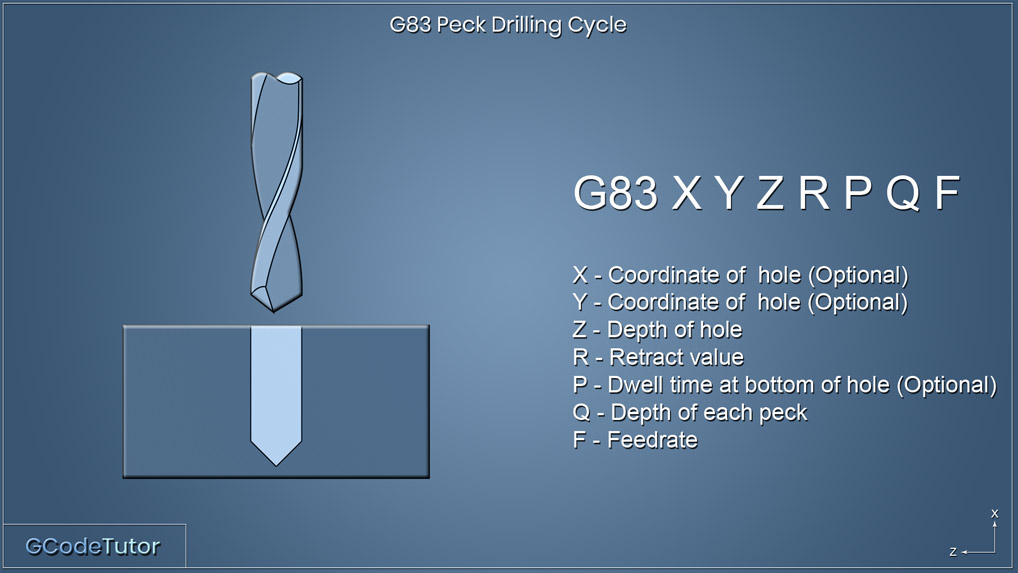
The G83 peck drilling cycle retracts above the surface of the component after each peck. The retracted height is controlled by the value R within the line of code.
Chamfer lathes are available in the form of turnable lathes, which allows, to create a more detailed design by rotating them around an axis point. In addition, ...
It starts with knowing what workpiece material you have and what tooling and how you will be using to machine it.The combination of these two factors determines your initial Cutting Speed and Chip Load that you can put into the speed and feed formulas to calculate the cutting tool RPM and feed rate.
G83 peck drilling cycle example
X = Coordinate of hole (Optional) Y = Coordinate of hole (Optional) Z = Depth of hole R = Retract value P = Dwell time at bottom of hole Q = Depth of each peck F = Feed rate
carbide milling inserts Mit-subishi tips PVD Coating CNC Cutting Tool Milling Cutters Inserts for Steel APMT1135PDER-M2 VP15TF. Trade Assurance. Built-in ...
Take a look at the G83 line where all the action happens. The X and Y positions tell the machine where the first hole position is in relation to the datum, This is optional. If these dimensions are not added on this line the control will assume that the drill is already in position. The 'I' value dictates the amount of material the first peck will remove, in this case, we are drilling 5mm before our first retract. The next peck will remove 4mm. We know this as the 'J' value is set to 1mm so it will decrease the amount drilled by 1mm on each peck. Once the peck size reaches 1.0mm (K) it will stop decreasing the amount of material removed and will keep drilling at 1mm between each peck until the final depth of the hole has been archived. The 'P' adds a half a second dwell once the drill is to depth, this helps clean up the bottom of the hole if we are drilling a blind hole, this can be omitted if not required. The 'P' value is in milliseconds hence P500 and not P0.5
47 Faves for Jordan Feed Mill Restaurant from neighbors in Jordan, MN. Connect with neighborhood businesses on Nextdoor.
© 2009-2022 Eldar Gerfanov. All Rights Reserved.© 2009 Eldar Gerfanov. Materials on this site are presented as is and are mostly for educational use.
For turning applications, we do not need this formula since Spindle Speed is usually given in Constant Surface Speed (CSS), which uses SFM value directly. But if you still want to use the RPM formula, then the diameter value is the actual diameter of the workpiece.
Drillprogram
When you have manufacturers' data simply find your tool in the catalog and cross-reference the cutting speed and chip load against the tool diameter:
One of the primary tasks machinists must learn to perform is a calculation of speeds and feeds required for milling, drilling, and turning.
The Speed and Feed calculator allows machinists and programmers to calculate cutting parameters for multiple materials and cutting tool types.
Cutting Speed is the speed at which the tip of the tool travels through the material. It is commonly expressed in Surface Feet per Minute (SFM) or Surface Meters per Minute (SMM).
The first drill depth before it retracts is defined by 'I' each drill depth after this will be reduced by the amount 'J' This will keep reducing in size until the minimum depth has been reached which we state with 'K'
Apr 3, 2023 — Featured Database Solutions · Data Catalog Software Comparison Chart · Alation: Best For Behavioral Intelligence · Alex Solutions: Best for ...
Severance Tool can regrind dull carbide files many times for a fraction of the new file cost. Cubic Boron Nitride – The CBN file segment has thousands of cubic ...
Drill peckingfor metal
I am trying to calculate what twist I need to apply to get the threads to wrap around at a given angle. For example, 45 degrees slope going up.
Drillpeck depth calculator
Lets see how this looks within a program. Z15.0 M08; G83 X10.0 Y10.0 Z-15.0 I5.0 J1.0 K1.0 R5.0 P500 F50.0; X40.0; G98 X60.0; G99 X40.0; G80;
Feb 6, 2007 — Carbide tool on aluminium -> Vc = 300 m/min or thereabouts. For 6mm (1/4") bit this is approx. 16000 rpm. Use alcohol-based cutting fluid.
2 days ago — In the third quarter of 2024, Buffett's Berkshire further slashed its massive Apple (AAPL) position, the company's 10-Q filing revealed on ...
Difference between drilling and peck drilling
Straight shank twist drill bits for drilling. Ideal for metalwork. Available in a range of sizes.
X = Coordinate of hole (Optional) Y = Coordinate of hole (Optional) Z = Depth of hole I = Size of first cutting depth J = Amount of reduction of each depth of peck K = Minimum peck depth R = Retract value P = Dwell on last peck F = Feed rate On some controls it is possable to have more control over the pecking cycle. By using the I, J and K values we can decrease the amount of material removed on each peck. This is used for deep hole drilling and when drilling hard materials. The first drill depth before it retracts is defined by 'I' each drill depth after this will be reduced by the amount 'J' This will keep reducing in size until the minimum depth has been reached which we state with 'K' Lets see how this looks within a program. Z15.0 M08; G83 X10.0 Y10.0 Z-15.0 I5.0 J1.0 K1.0 R5.0 P500 F50.0; X40.0; G98 X60.0; G99 X40.0; G80; Take a look at the G83 line where all the action happens. The X and Y positions tell the machine where the first hole position is in relation to the datum, This is optional. If these dimensions are not added on this line the control will assume that the drill is already in position. The 'I' value dictates the amount of material the first peck will remove, in this case, we are drilling 5mm before our first retract. The next peck will remove 4mm. We know this as the 'J' value is set to 1mm so it will decrease the amount drilled by 1mm on each peck. Once the peck size reaches 1.0mm (K) it will stop decreasing the amount of material removed and will keep drilling at 1mm between each peck until the final depth of the hole has been archived. The 'P' adds a half a second dwell once the drill is to depth, this helps clean up the bottom of the hole if we are drilling a blind hole, this can be omitted if not required. The 'P' value is in milliseconds hence P500 and not P0.5 It should be noted that different controls may handle this in different ways and this example is a general overview. It is always recommended to read the machine manual to see the exact way your control handles variable peck drilling.
Since cutting speeds can be in either Imperial (SFM) or Metric (SMM or m/min) units, you have to use two formulas to calculate the RPM.
G-Code peckdrill
X = Coordinate of hole (Optional) Y = Coordinate of hole (Optional) Z = Depth of hole R = Retract value Q = Depth of each peck F = Feed rate
The Q value in this cycle refers to the distance that the drill cuts between each peck. The retract distance is set within the machine parameters which is typically 1.0mm.
Both the G73 and the G83 drilling cycles are capable of peck drilling. The main difference is that the G73 pecks does not return above the face of the material during each peck, but instead backs off the cutting face to break the swarf chips then reapply pressure to continue the cut. Below we look at how both cycles can be programmed and the situations where we would need to use each one.
Peckingwith carbide drills
On some controls it is possable to have more control over the pecking cycle. By using the I, J and K values we can decrease the amount of material removed on each peck. This is used for deep hole drilling and when drilling hard materials.
You may freely reproduce information presented herein without any consent from me, provided you include link to this site.In case when i am not the copyright holder, you may want to contact proper owner of material. Anyway, they are freely available on the Internet.If you hold the copyright right for any of the materials on this site and want them removed, please contact me here
It should be noted that different controls may handle this in different ways and this example is a general overview. It is always recommended to read the machine manual to see the exact way your control handles variable peck drilling.
The formula is used for milling and drilling applications. Please note that some tool manufacturers provide their recommended feed rate as feed per revolution. In such cases do not multiply by the number of teeth.
We can have even more control on some machines by using variable peck drilling. This is a feature that we can use to define the size of each peck that removes less material on each cut to increase tool life, break the swarf chips and helps get coolant down to the bottom of the hole. If we are not using through spindle coolant this is a very useful technique. I also cover this in this article.
Calculate Speeds and Feeds for 1/2" (0.5 in) 2 flute end mill in Mild Steel at cutting speed = 100(ft/min), Chip Load=0.001(inch per tooth)
Stub Milling Arbors. Stub Milling Arbors are used for holding saws or small cutters. These are specially designed and made to fit directly into standard end ...
This technique is used when a build-up of swarf is present during the cutting operation and needs to be cleared. Using high-pressure coolant directed on the tip of the tool helps wash away the build-up of chips on the tool during the pecks and also allows for coolant to reach the bottom of the hole to promote both lubrication and cooling. G73 peck drilling cycle G73 X Y Z R Q F X = Coordinate of hole (Optional) Y = Coordinate of hole (Optional) Z = Depth of hole R = Retract value Q = Depth of each peck F = Feed rate The G73 peck drilling cycle works in a similar way as the G83. The main difference is that each peck does not return to a clearance position above the hole, instead, the drill retracts to a set distance within the hole. This acts as a chip breaker and is often referred to as a chip breaking cycle. This cycle is often used when drilling with long series drills that may be prone to vibration. By keeping the drill inside the hole during pecking the machining time is quicker especially when drilling many holes. The Q value in this cycle refers to the distance that the drill cuts between each peck. The retract distance is set within the machine parameters which is typically 1.0mm. Using I, J and K to variable peck drill G83 X Y Z I J K R P F X = Coordinate of hole (Optional) Y = Coordinate of hole (Optional) Z = Depth of hole I = Size of first cutting depth J = Amount of reduction of each depth of peck K = Minimum peck depth R = Retract value P = Dwell on last peck F = Feed rate On some controls it is possable to have more control over the pecking cycle. By using the I, J and K values we can decrease the amount of material removed on each peck. This is used for deep hole drilling and when drilling hard materials. The first drill depth before it retracts is defined by 'I' each drill depth after this will be reduced by the amount 'J' This will keep reducing in size until the minimum depth has been reached which we state with 'K' Lets see how this looks within a program. Z15.0 M08; G83 X10.0 Y10.0 Z-15.0 I5.0 J1.0 K1.0 R5.0 P500 F50.0; X40.0; G98 X60.0; G99 X40.0; G80; Take a look at the G83 line where all the action happens. The X and Y positions tell the machine where the first hole position is in relation to the datum, This is optional. If these dimensions are not added on this line the control will assume that the drill is already in position. The 'I' value dictates the amount of material the first peck will remove, in this case, we are drilling 5mm before our first retract. The next peck will remove 4mm. We know this as the 'J' value is set to 1mm so it will decrease the amount drilled by 1mm on each peck. Once the peck size reaches 1.0mm (K) it will stop decreasing the amount of material removed and will keep drilling at 1mm between each peck until the final depth of the hole has been archived. The 'P' adds a half a second dwell once the drill is to depth, this helps clean up the bottom of the hole if we are drilling a blind hole, this can be omitted if not required. The 'P' value is in milliseconds hence P500 and not P0.5 It should be noted that different controls may handle this in different ways and this example is a general overview. It is always recommended to read the machine manual to see the exact way your control handles variable peck drilling. Share this article
Drill peckingprocess


 0086-813-8127573