
Precision Carbide End-mills - end mill bit
Kennametal turninginsertnomenclature
The mathematical expression denoting one of several parameters that describe surface texture (same as average roughness Ra). Average roughness is the arithmetic average height deviation of the measured surface profile from the profile centerline. See surface texture.
Stack Exchange network consists of 183 Q&A communities including Stack Overflow, the largest, most trusted online community for developers to learn, share their knowledge, and build their careers.
Edmund Isakov, Ph.D., is a consultant, writer and frequent CTE contributor. He is the author of the books “Mechanical Properties of Work Materials” (Modern Machine Shop Publications, 2000); “Engineering Formulas for Metalcutting” (Industrial Press, 2004); “Cutting Data for Turning of Steel” (Industrial Press, 2009); the CD-ROM “International System of Units (SI)” (Industrial Press, 2012); and the software “Advanced Metalcutting Calculators” (Industrial Press, 2005). For more information, call (561) 369-4063 or visit www.edmundisakovphd.com.
I tried tapping by hand with a M5x0.8 tap, and it simply can't start. My taps are not high quality and my technique barely reaches newbie levels.
You will need a CNC milling machine, to perform this. Sandvik provides some information on the process (Not affiliated in any way). Thread milling also means that there's no risk of destroying the part with a stuck tap.
The seventh position indicates the cutting point configuration: a radius or a facet. In the case of a radius, the number indicates how many of 1 ⁄ 64 of an inch in the radius: 0 – sharp corner (0.002" max. radius); 0.2 – 0.004"; 0.5 – 0.008"; 1 – 1 ⁄ 64"; 2 – 1 ⁄ 32"; 3 – 3 ⁄ 64"; 4 – 1 ⁄ 16"; 5 – 5 ⁄ 64"; 6 – 3 ⁄ 32"; 7 – 7 ⁄ 64"; 8 – 1 ⁄ 8"; 10 – 5 ⁄ 32"; 12 – 3 ⁄ 16" 14 – 7 ⁄ 32" = 14; 16 – 1 ⁄ 4"; X – Any other corner radius.
The sixth position is a significant one- or two-digit number indicating the number of sixteenths of an inch in the thickness of the insert. It is a one-digit number when the number of sixteenths of an inch in the thickness is a whole number: 1 – 1 ⁄ 16"; 2 – 1 ⁄ 8"; 3 – 3 ⁄ 16"; 4 – 1 ⁄ 4"; 5 – 5 ⁄ 16"; 6 – 3 ⁄ 8"; 7 – 7 ⁄ 16"; 8 – 1 ⁄ 2"; 9 – 9 ⁄ 16"; 10 – 5 ⁄ 8".
There are 14 tolerance classes that control the indexability of the inserts. Each class is denoted by a capital letter. Letters for tolerances are A, B, C, D, E, F, G, H, J, K, L, M, U and N.
Milling insert specificationpdf
Tool that cuts a sloped depression at the top of a hole to permit a screw head or other object to rest flush with the surface of the workpiece.
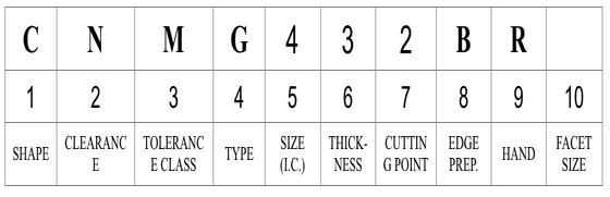
1. Shape2. Clearance3. Tolerance class4. Type5. Size6. Thickness7. Cutting-point configuration8. Edge preparation9. Hand10. Facet size
In case of a facet, two letters are used. The first letter designates the facet angle: A – 45°; D – 60°; E – 75°; G – 87°; P – 90°; Z – Any other facet angle. The second letter designates the facet clearance angle:
Milling insert specificationchart
Reminder: Answers generated by artificial intelligence tools are not allowed on Home Improvement Stack Exchange. Learn more
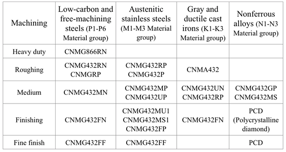
Inserts selection depends on workpiece material, chip control, surface finish, tool life, and the machine tool’s power and torque requirements. One of the commonly used indexable inserts for general turning is CNMG 432.
As part of the POC I've got a ball bearing with an extended flange on one side. There are two M5 threaded holes in this flange with grub screws, and they are about 120 degrees apart. I want to add a third hole to balance this out and provide a positive grasp on longer stock.
Space provided behind the cutting edges to prevent rubbing. Sometimes called primary relief. Secondary relief provides additional space behind primary relief. Relief on end teeth is axial relief; relief on side teeth is peripheral relief.
Carbideinsertidentification chart
An alternative idea (Kudo to @Sanchises) would be to make the bearing larger and insert an tube of mild steel, similar the entended flange bearing.
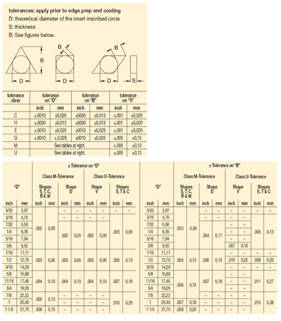
Tolerances on dimensions (± from nominal) are denoted by letters A, B and T. Dimension A is the nominal inscribed circle (I.C.) of the insert. Dimension T is the thickness of the insert. For pentagon, triangle and trigon shapes, dimension B is the insert height, i.e., the distance between one side and the opposite corner (Figure 2).
Conditioning of the cutting edge, such as a honing or chamfering, to make it stronger and less susceptible to chipping. A chamfer is a bevel on the tool’s cutting edge; the angle is measured from the cutting face downward and generally varies from 25° to 45°. Honing is the process of rounding or blunting the cutting edge with abrasives, either manually or mechanically.
Nine relief angle values have been described in ANSI B212.12-1991 standard. These angles are the difference from 90° measured in a plane normal to the cutting edge generated by the angle between the flank and top surface of the insert. Each relief angle is denoted by a capital letter as follows:
Milling insert specificationexample
There are 16 standard shapes of indexable inserts, and each shape is identified by a capital letter as follows (Figure 1):
Explanation: Enter each code position to decode the specific insert characteristics according to ANSI B212.4-2002 standards.
You can drill out the hole to a larger size, insert a piece of copper inside the main bore and then fill up the drilled hole with weld metal. TIG might be the best process, using rod suitable for mild steel. Once the hole is filled up with steel, drill the hole again and tap it in the usual fashion. The weld metal that fills the former hole won't be hardened steel.
Space provided behind a tool’s land or relief to prevent rubbing and subsequent premature deterioration of the tool. See land; relief.
I am trying to make an extended support for my tiny Sherline lathe, to turn items longer than the bed. Essentially it’s a steady-rest that bolts beyond the end of the bed.
You'll probably have to mill threads. This doesn't use a tap, but rather a cutting tool with the thread form. The cutting tool is smaller (in this case 3.8mm) than the hole, so it's inserted, and moved in a circular fashion to cut threads around the hole.
Milling insert specificationchart pdf
The 10th position is only used if there are letters in the seventh position. It will be a significant number representing the nominal sixty-fourths of an inch in length of the primary facet: 1 – 1 ⁄ 64"; 2 – 1 ⁄ 32"; 3 – 3 ⁄ 64"; 4 – 1 ⁄ 16"; 5 – 5 ⁄ 64"; 6 – 3 ⁄ 32"; 7 – 7 ⁄ 64"; 8 – 1 ⁄ 8"; 9 – 9 ⁄ 64"; 10 – 5 ⁄ 32".
My plan B is to drill the existing holes to 5mm and then epoxy a thin M5 locknut on the inside of the bore. This should work, because the forces will mostly be radially outward, but it will also take away from the limited through-hole space.
Milling insert specificationmetric
For all other polygons, dimension B is the distance, measured along the bisector of the rounded off corner angle and a gage roll of nominal I.C. size tangent to the two sides opposite the corner (Figure 2). For example, if a tolerance letter is H, tolerances on dimensions (± from nominal) are: 0.0005" on dimension A, 0.0005" on dimension B and 0.001" on dimension T.
Workpiece is held in a chuck, mounted on a face plate or secured between centers and rotated while a cutting tool, normally a single-point tool, is fed into it along its periphery or across its end or face. Takes the form of straight turning (cutting along the periphery of the workpiece); taper turning (creating a taper); step turning (turning different-size diameters on the same work); chamfering (beveling an edge or shoulder); facing (cutting on an end); turning threads (usually external but can be internal); roughing (high-volume metal removal); and finishing (final light cuts). Performed on lathes, turning centers, chucking machines, automatic screw machines and similar machines.
Angle of inclination between the face of the cutting tool and the workpiece. If the face of the tool lies in a plane through the axis of the workpiece, the tool is said to have a neutral, or zero, rake. If the inclination of the tool face makes the cutting edge more acute than when the rake angle is zero, the rake is positive. If the inclination of the tool face makes the cutting edge less acute or more blunt than when the rake angle is zero, the rake is negative.
Steelmilling insert specification
The fifth position is a significant one- or two-digit number indicating the size of the inscribed circle (I.C.) for all inserts having a true I.C. such as Round, Square, Triangle, Trigon, Pentagon, Hexagon, Octagon, and Diamond. This position designates the number of eighths of an inch in the nominal size of the I.C. It will be a one-digit number when the number of eighths of an inch in the I.C. is a whole number: 1 – 1 ⁄ 8"; 2 – 1 ⁄ 4"; 3 – 3 ⁄ 8"; 4 – 1 ⁄ 2"; 5 – 5 ⁄ 8"; 6 – 3 ⁄ 4"; 7 – 7 ⁄ 8";
Do I have to anneal/soften the flange somehow? I've removed the dust seals and disassembly looks risky with no obvious removal process.
Due to the magazine’s space limitations, the authors provide the following tables showing most popular Kennametal’s indexable inserts only for general turning of steel, cast iron, and nonferrous alloys. These tables don’t cover all Kennametal chip breakers. (Figure 4 and Figure 5 also show Kennametal Inc. insert identification system and chip breaker identification system respectively.)
1. Shape (e.g., A, C, D): 2. Clearance (e.g., A, B, C): 3. Tolerance Class (e.g., A, B, C): 4. Type (e.g., A, B, C): 5. Size Code: 6. Thickness Code: 7. Cutting-Point Configuration (e.g., 0, 0.5, A): 8. Edge Preparation (e.g., A, B, C): 9. Hand (R, L, N): 10. Facet Size: Decode Insert
About the Authors: Edmund Isakov, Ph.D., is a consultant, writer, and frequent CTE contributor. He is the author of four books “Mechanical Properties of Work Materials” (Modern Machine Shop Publications, 2000); “Engineering Formulas for Metalcutting” (Industrial Press, 2004); “Cutting Data for Turning of Steel” (Industrial Press, 2009); “International System of Units (SI)” the CD-ROM (Industrial Press, 2013); and the software “Advanced Metalcutting Calculators” (Industrial Press, 2005). For more information, call (561) 369-4063, or email: edmundisakov9701@comcast.net. Shi ‘Steve’ Chen is Manager Product Engineering Turning at Kennametal Inc. For more information, call (724) 539-5321, or email: Shi.Chen@Kennametal.com
It will be a two-digit number carried to one decimal place when it is not a whole number: 1.2 – 5 ⁄ 32"; 1.5 – 3 ⁄ 16"; 1.8 – 7 ⁄ 32"; 2.5 – 5 ⁄ 16".
American National Standard ANSI B212.4-2002 covers the identification system for indexable-type inserts for both single-point and multiple-point cutting tools. It was published on October 29, 2002. The earlier editions of the standard are:
It is a two-digit number carried to one decimal place when it is not a whole number: 1.2 – 5 ⁄ 64"; 1.5 – 3 ⁄ 32"; 2.5 – 5 ⁄ 32"; 3.5 – 7 ⁄ 32".
Replaceable tool that clamps into a tool body, drill, mill or other cutter body designed to accommodate inserts. Most inserts are made of cemented carbide. Often they are coated with a hard material. Other insert materials are ceramic, cermet, polycrystalline cubic boron nitride and polycrystalline diamond. The insert is used until dull, then indexed, or turned, to expose a fresh cutting edge. When the entire insert is dull, it is usually discarded. Some inserts can be resharpened.
The fourth position is a capital letter denoting differences in design of insert, such as the existence of fixing holes, countersinks and special features on rake surfaces. There are 15 standard types in design as follows (Figure 3):
According to ANSI B212.4-2002 standard, identification of the indexable insert includes 10 positions denoted by a capital letter. Each position (from 1 to 10) defines a characteristic of the insert in the following order:
On rectangular and parallelogram inserts, the width and length dimensions are used in place of the I.C. A two-digit number designates the sizes of these inserts. The first digit indicates the number of eighths of an inch in the width and the second digit indicates the number of fourths of an inch in the length of the insert.
Imaginary circle that touches all sides of an insert. Used to establish size. Measurements are in fractions of an inch and describe the diameter of the circle.
ANSI B212.4-2002 standard added one more capital letter O, which denotes other relief angles for new designs of indexable inserts.
I don't know if it fits in your project: you could also shrink-fit an ring of mild steel on the outside. In the ring you can easily make aligning threaded holes.


 0086-813-8127573