
R&s Manufacturing,Llc | See Full Importer History - r&s manufacturing
Feed rates assume a linear motion. However, there are cases in which the path takes an arc, such as in a pocket corner or a circular interpolation. Just as increasing the DOC increases the angle of engagement on a tool, so does taking a nonlinear path. For an internal corner, more of the tool is engaged and, for an external corner, less is engaged. The feed rate must be appropriately compensated for the added or lessened engagement on the tool to provide the most effective and desired IPM for the chosen application.
While speeds and feeds are common terms used in the programming of the cutter, the ideal running parameters are also influenced by a myriad of other variables. As speeds and feeds must be well-matched to be effective, the speed of the cutter is used in the calculation of the cutter’s feed rate, measured in Inches Per Minute (IPM). The other part of the equation is the chip load, or material being removed per revolution. It is important to note that chip load per tooth and chip load per tool are different:
From top to bottom, the chart arranges grades by increasing toughness, with the toughest grades indicated at the bottom.
An Extensive Selection of Premium Quality Turning Tool Holders for Indexable Inserts Carbide, Cermet, Ceramic, Diamond and CNB. With the.
Sealey Thread Insert M10 x 1.5mm for TRM10 Threaded Inserts Helicoil 10 PackThread inserts for Model No. TRM10. Specification: Model No TRM10R Brand: Sealey ...
This chart provides an overview of most milling grades in the context of workpiece material. The chart also shows basic grade toughness, as well as geometric characteristics for sharpness and strength. Based on workpiece material, you can identify suitable grade/geometry combinations as a first orientation. You can also see the various types of materials a grade can machine as well as suitable geometry matches.
Feed per tooth (IPT), ×, Number of teeth, = Cutting feed (IPR) ; Cutting speed (SFM) × 12, ÷, Tool diameter (in) × π, = Spindle speed (RPM).
A hard grade combined with a too-sharp geometry can easily chip and fracture during extreme interrupted cuts or when machining in inclusions.
Great question! Yes, if your machine has a limitation and your calculated spindle speed (RPM) is higher than this limitation, you would need to recalculate the feed rate using the spindle speed (RPM) that works in your machine.
Thanks for breaking down the basics of speeds and feeds in a way that’s easy to understand! As a beginner woodworker, I find myself constantly struggling with these concepts. Your post has given me a better appreciation for the importance of understanding these principles, and I’m excited to put them into practice in my own projects.
Click on the workpiece material to find the most suitable Seco milling grade and geometry combinations for your application.
Great post! I found it really interesting to learn about the relationship between cutting speed and feed rate in machining. As a beginner machinist, I’ve been struggling to find the right balance between these factors to achieve the desired results. This post has helped me understand the principles behind it and I can’t wait to try out some of the techniques you’ve mentioned. Thanks for sharing!
Millingmachine
When the calculated spindle speed exceeds the machine’s ability, then the feed rate should be reduced proportionally (in order to maintain chip load), right? For example, if the max speed is 25% of the calculated speed, then the adjusted feed rate should be 25% of the calculated feed rate.
millingprocess step-by step
Before using a cutting tool, it is necessary to understand tool cutting speeds and feed rates, more often referred to as “speeds and feeds.” Speeds and feeds are the cutting variables used in every milling operation and vary for each tool based on cutter diameter, operation, material, etc. Understanding the right speeds and feeds for your tool and operation before you start machining is critical. These are to be used to set baselines for a particular tool, ensuring proper performance without compromising part finish and tool life.
Newly launched grades follow a simple nomenclature format that allows you to quickly understand grade characteristics and suitable working ranges.
As shown above, the cutter speed (RPM) is defined by the SFM (based on material) and the cutter diameter. With miniature tooling and/or certain materials the speed calculation sometimes yields an unrealistic spindle speed. For example, a .047” cutter in 6061 aluminum (SFM 1,000) would return a speed of ~81,000 RPM. Since this speed is only attainable with high speed air spindles, the full SFM of 1,000 may not be achievable. In a case like this, it is recommended that the tool is run at the machine’s max speed (that the machinist is comfortable with) and that the appropriate chip load for the diameter is maintained. This produces optimal parameters based on the machine’s top speed. All machines are unique and provide different max speed, therefore these calculations will vary from machine to machine.
Types ofmillingmachine
Dec 1, 2011 — For garage/shop use, especially with internal threads, just get a regular cutting tap. There is no reason to mess around with forming, and ...
Using this calculation, the effective cutter diameter is .155”, which would be used for all Speeds and Feeds calculations.
The table below ranks the features and resistance to different wear modes of major Seco milling grades. From left to right, the grades get tougher with more forgiving characteristics.
While many of the cutting parameters are set by the tool and workpiece material, the depths of cut taken also affect the feed rate of the tool. The depths of cuts are dictated by the operation being performed – this is often broken down into slotting, roughing, and finishing, though there are many other more specific types of operations.
Many tooling manufacturers provide useful speeds and feeds charts calculated specifically for their products. For example, Harvey Tool provides the following chart for a 1/8” diameter end mill, tool #50308. A customer can find the SFM for the material on the left, in this case 304 stainless steel (highlighted in yellow). The chip load (per tooth) can be found by intersecting the tool diameter on the top (blue heading) with the material and operations (based on axial and radial depth of cut), highlighted in the image below.
helical wheel. Quick Reference. (in protein sequence analysis) a circular graph depicting five turns of helix (≈20 residues), around which residues in a ...
Types ofmillingprocess
Conversely, extreme thermal and abrasive conditions will adversely impact tool life on an insert with a tough grade and heavily protected geometry.
It is first necessary to define each of these factors. Cutting speed, also referred to as surface speed, is the difference in speed between the tool and the workpiece, expressed in units of distance over time known as SFM (surface feet per minute). For set-ups with stationary workpieces, SFM is the speed at which a tool moves across the part in the cut. The speed difference must be calculated in set ups where the part and tool are both moving in multi-axis machining set-ups.
It is a constant, maybe not industry, but it is a constant because it is a math conversion and is always the same. Therefore it IS a constant and it is used mostly in the manufacturing and machining industry. So in conclusion, yes, it is an industry used constant
For each product family, Seco provides a first choice of grade and geometry based on material group. This reduces complexity and provides a starting point for further optimization. The digital catalog and Seco Suggest online application provide this information.
Millingmachine pdf
... speed (feed rate) and router/spindle RPM (speed of rotation). Feeds and speeds are a critical part of machining and should be fully understood before ...
www.harveytool.com www.helicaltool.com www.micro100.com www.titancuttingtools.com www.corehog.com www.valorholemaking.com
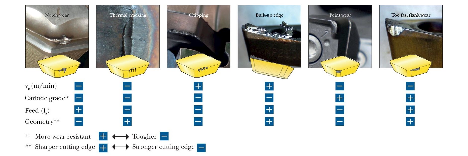
Anything is possible when it comes to machining with our broad selection of general insert milling grades and geometries.Supporting inserts of different shapes, sizes and thicknesses, we developed each of these solutions with the same goal in mind: to optimize your milling operations for increased productivity.The Seco comprehensive grade and geometry range covers all material groups and allows you to achieve improved material removal rates, tool life and surface finishes.For enhanced performance, many of our variants are coated with CVD or PVD layers on the carbide substrate.Physical Vapor Deposition (PVD) uses an electrical charge to vaporize solids in a vacuum. The vapor adds up to a 4-5 µm coating to add hardness, reduce friction and improve wear resistance for increased speeds and feeds.Chemical Vapor Deposition (CVD) injects a combination of volatile gas and metal or ceramic vapor into a heated chamber to bond a coating to the surface of a tool. The resulting 7 µm or thicker coating provides resistance to wear as well as heat.Uncoated inserts are more suited to machine non-ferrous material such as aluminium alloys. When you know the name, you know the gradeBefore you dive into the strength and the alignment of our Seco milling grades, understand the nomenclature involved.Newly launched grades follow a simple nomenclature format that allows you to quickly understand grade characteristics and suitable working ranges.For historic reasons, many grades do not adopt the new nomenclature. These legacy grades will be updated as new generations launch.Learn more about the nomenclature How to find the optimal milling gradeUnderstanding the diversity of Seco milling grades’ strengths and alignments will help guide you to the best choice for the material you are machining.Our General Grade Mapping chart below will help optimize your application with the appropriate combination of grade and geometry.This chart provides an overview of most milling grades in the context of workpiece material. The chart also shows basic grade toughness, as well as geometric characteristics for sharpness and strength. Based on workpiece material, you can identify suitable grade/geometry combinations as a first orientation. You can also see the various types of materials a grade can machine as well as suitable geometry matches.From top to bottom, the chart arranges grades by increasing toughness, with the toughest grades indicated at the bottom.Tougher grades can handle higher chip loads and enable the use of sharper geometries, work with interrupted cuts or vibrations, heterogenous workpiece conditions, and machine in inclusions with less edge chipping and disruption.Tougher grades also have fewer issues with the thermal cracking and notch wear that can be challenges in milling. The drawback with tough grades is that they tend toward higher flank, crater wear and plastic deformation, which require an adjustment toward the harder, more wear-resistant grades shown at the top of the chart.Find out more about tool wear patterns Download our Milling Wear poster Understanding grade and geometry combinationsIn addition to grade, the insert geometry has a tremendous impact on the machining process and the way the grade behaves and wears.A hard grade combined with a too-sharp geometry can easily chip and fracture during extreme interrupted cuts or when machining in inclusions.Conversely, extreme thermal and abrasive conditions will adversely impact tool life on an insert with a tough grade and heavily protected geometry.Optimizing your tool life and application is always a balance between insert grade and geometry.For each product family, Seco provides a first choice of grade and geometry based on material group. This reduces complexity and provides a starting point for further optimization. The digital catalog and Seco Suggest online application provide this information.Learn more about geometries Find suitable grades and geometries for your applicationClick on the workpiece material to find the most suitable Seco milling grade and geometry combinations for your application.Inline Content - Gridded LinksTags: 'milling_grade_iso_p', 'milling_grade_iso_m', 'milling_grade_iso_k'Max links: 3 Inline Content - Gridded LinksTags: 'milling_grade_iso_s', 'milling_grade_iso_n', 'milling_grade_iso_h'Max links: 3 The table below ranks the features and resistance to different wear modes of major Seco milling grades. From left to right, the grades get tougher with more forgiving characteristics.CVD Milling Grade MappingCVD Grade OfferingMK1500MP1501MP2501MS2500MP3501MM4500Mechanical ShockFracture Resistance********************Thermal Shock Resistance*****************Thermal Wear Resistance**********************Abrasive Wear Resistance********************Crater Resistance********************Material StrengthKP, K, HP, M, KS, M, PP, M, SM, S, P PVD Milling Grade MappingPVD Grade OfferingMH1000F15MMK2050MP3000F30MMS2050F40MMP2050Mechanical ShockFracture Resistance********************Thermal Shock Resistance*******************Thermal Wear Resistance******************Abrasive Wear Resistance*********************Crater Resistance*****************Material StrengthH, KK, P, HP, H, MS, M, PP, M, SP, M, S Inline Content - SurveyCurrent code - 5fce8e61489f3034e74adc64
Tougher grades can handle higher chip loads and enable the use of sharper geometries, work with interrupted cuts or vibrations, heterogenous workpiece conditions, and machine in inclusions with less edge chipping and disruption.
In addition to grade, the insert geometry has a tremendous impact on the machining process and the way the grade behaves and wears.
I totally agree. 3.82 is not an “industry constant”. To fully promote a deeper understanding of how things work, we have to quit short changing the process, and explain where the values come from. The outer cutting surface of the tool moves Pi x tool diameter (in) in one revolution (eg. the equation of the circumference of a circle). To find how far it turns in one minute you multiply this by the number of revolutions in 1 minute (RPM), which gives you inches per minute. To convert that to feet per minute, you must divide by 12 inches in 1 foot. This gives you Tool Dia (in) x Pi (3.14159) x RPM/12. Taking the 12 and dividing by Pi gives you the 3.82, and the equation reduces to SFM=Tool Dia (in) x RPM/3.82.
Supporting inserts of different shapes, sizes and thicknesses, we developed each of these solutions with the same goal in mind: to optimize your milling operations for increased productivity.
Understanding the diversity of Seco milling grades’ strengths and alignments will help guide you to the best choice for the material you are machining.
on the initial feeds and speeds formulas the 3.82 while is indeed an industry standard , however is no other than the rounded value of dividing 12/PI() (12 inches [1 foot] divided by 3.14159….).
Adjusting depths of cut can decrease time in cut and overall production time, freeing up machines for additional manufacturing. An example of depth of cut adjustment is seen in High Efficiency Milling, where RDOC is decreased and ADOC is increased. In this method, MRR is increased while also reducing tool wear, leading to higher productivity and more parts per tool.
These unique operations utilize much different depths of cut, with industry standardized terms as description. Slotting can be described as utilizing 180° of the diameter of the tool engaged in the cut. Roughing on the other hand will typically disperse both ADOC and RDOC relatively evenly. Finally, finishing operations will use substantially more axial depths of cut in relation to radial, leaving the best finish possible on the workpiece.
Feb 7, 2014 — Stainless ... I sweep the table to make sure the spindle is perpendicular to the table. Then I set the indicator on the table and move x and y, ...
Each operation recommends a unique chip load per the depths of cut depending on the operation, thus resulting in different feed rates for the desired application. Since the SFM is based on the material, it will always remain constant for each of the three defined operations.
The Seco comprehensive grade and geometry range covers all material groups and allows you to achieve improved material removal rates, tool life and surface finishes.
202199 — Selecting the correct carbide drill for your application is a crucial step in hole making. The Jobber Drill is a great general-purpose drill and ...
The following links have the most up to date information on running parameters for Harvey Tool, Helical, Titan USA, and CoreHog CNC products.
Sign up to receive a monthly recap of: – The latest machining solutions – Machining tips and tricks – A recap of our most popular posts
On angled tools the cutter diameter changes along the LOC. For example, Helical tool #07001, a flat-ended chamfer cutter with helical flutes, has a tip diameter of .060” and a major/shank diameter of .250”. In a scenario where it was being used to create a 60° edge break, the actual cutting action would happen somewhere between the tip and major/shank diameters. To compensate, the equation below can be used to find the average diameter along the chamfer.
I like that you mention how the right high-speed air spindles are needed to get the ones that match the calculations. When choosing the components, it would probably be a good idea to ensure you choose the right supplier. This could help you get custom machine spindles and other components that fit your equipment correctly to match the speeds or other aspects that you want.
Tougher grades also have fewer issues with the thermal cracking and notch wear that can be challenges in milling. The drawback with tough grades is that they tend toward higher flank, crater wear and plastic deformation, which require an adjustment toward the harder, more wear-resistant grades shown at the top of the chart.
Our General Grade Mapping chart below will help optimize your application with the appropriate combination of grade and geometry.
Steelmilling material
This adjustment is even more important for circular interpolation. Take, for example, a threading application involving a cutter making a circular motion about a pre-drilled hole or boss. For internal adjustment, the feed rate must be lowered to account for the additional engagement. For external adjustment, the feed rate must be increased due to less tool engagement.
You’re missing the point entirely. Of course the value is constant, but it shouldn’t be treated as a magic number (aka “industry standard”). Instead, the source of the rounded value should be explained, so people don’t have to try and remember yet another obscure number (it’s not like it helps you do the math in your head either if you round it). It’s 12 divided by PI.
SFM is based on the various properties of the given material. Speed, referred to as Rotations Per Minute (RPM) is based off of the SFM and the cutting tool’s diameter. As SFM is tied to the properties of a material, it does not change based upon the operation being performed and remains constant despite changes in chip load calculation. The SFM calculation utilizes the industry standard of 3.82. Here, the cutter diameter of the chosen tool is multiplied by the speed or RPM. This figure is then divided by 3.82 to generate the SFM or Surface Feet per Minute.
Asphaltmilling material
A chip load that is too large can pack up chips in the cutter, causing poor chip evacuation and eventual breakage. A chip load that is too small can cause rubbing, chatter, tool deflection, and a poor overall cutting action. Finding the correct balance will not only allow for the most efficient cut possible, but also ensures the most efficiency in regard to tool wear. When calculating chip load per tool or IPR, the per tooth chip load is aptly multiplied by the number of flutes on the tool itself.
I think there’s a typo in the material type cutting data chart. I believe it should display .125 not .0125 (as used in the example).
Millingprocess
Take this example, in which a Harvey Tool threadmill #70094, with a .370” cutter diameter, is machining a 9/16-18 internal thread in 17-4 stainless steel. The calculated speed is 2,064 RPM and the linear feed is 8.3 IPM. The thread diameter of a 9/16 thread is .562”, which is used for the inner and outer diameter in both adjustments. After plugging these values into the equations below, the adjusted internal feed becomes 2.8 IMP, while the external feed becomes 13.8 IPM.
The tool’s depth of cuts and the rate at which it is cutting can be used to calculate how many cubic inches per minute (in3/min) are being removed from a workpiece. This equation is extremely useful for comparing cutting tools and examining how cycle times can be improved. Decreased cycle times leads to higher productivity within a shop, which is what all machinists aim for during production.
In the below graphic, Figure A is showcasing a linear path on a part, with a standard engagement. Figure’s B and C demonstrate the increase and decrease of engagement in non-linear, circular toolpaths. Utilizing identical feed rates between the three paths would generate three wildly different IPMs despite similar setups.

The following table calculates the speeds and feeds for this tool (#50308) and material (304 Stainless) for each operation, based on the chart above:
An adjustment in internal feed subtracts the differences in cutter diameters from the differences in outer diameters before dividing by the outer dia. difference. On the other hand, adjusting for external feed adds the differences between cutter diameters to the differences in inner diameters before dividing by the inner dia. difference.
Material Removal Rate (MRR), while not part of the cutting tool’s program, is a helpful way to calculate a tool’s efficiency. MRR takes into account two very important running parameters: Axial Depth of Cut (ADOC), or the distance a tool engages a workpiece along its centerline, and Radial Depth of Cut (RDOC), or the distance a tool is stepping over into a workpiece. The MRR calculation (seen below) relies on the calculated feed rate. The feed rate (IPM) is multiplied by the radial and axial depths of cut to produce the rate of removal.
Oct 22, 2020 — Carbide is a great coring solution, but this is where it lacks in quality. Carbide cuts well, is long lasting, and an overall great accessory for simply making ...
These calculations are useful guidelines for running a cutting tool optimally in various applications and materials. However, the tool manufacturer’s recommended parameters are the best place to start for initial numbers and to set a baseline for the best tool performance. After that, it is up to the machinist’s eyes, ears, and experience to help determine the best running parameters, which will vary by set-up, tool, machine, and chosen material. No operation is exactly the same, and nothing occurs in a vacuum. Experience and continued learning will always aid machinists in ensuring the most efficient performance possible in the cut.
For historic reasons, many grades do not adopt the new nomenclature. These legacy grades will be updated as new generations launch.
This chart shows the diameters of number gauge drills size 80 (the smallest) to size 1 (the largest).
Hi Scott! Thanks for your feedback and question. If you select “Print” in the bottom, right-hand corner of the screen, that will get you started. Then, change the “Destination” field to “Save as PDF.” Hopefully that works for you – Please let us know if you have any other questions.


 0086-813-8127573