
Reed Mfg. Co. DEB4 - Deburr/Chamfer Tool for Plastic Pipe - plastic pipe chamfering tool
In conventional tapping applications, as with most machining applications, chip evacuation is a concern. This is especially true in blind holes, or holes with a bottom, as chips created at the very bottom of the hole oftentimes have a long distance to travel before being efficiently evacuated. With form taps, however, chip removal is never a concern.
Are you planning a general home renovation? Go ahead and check our stair calculator and the decking calculator – they may come in handy!
In manual mode, you can set the cutting speed (usually in surface feet per minute – sfm), and it will output the rotation speed in rotations per minute (rpm), therefore converting sfm to rpm. You can also set custom chip loads to calculate the feed rates. Let's look at each mode in detail next.
I have worked with formed threads on some of our assemblies and I’m not a fan. If the drilled hole is slightly too large, it seem that a double helix can form.
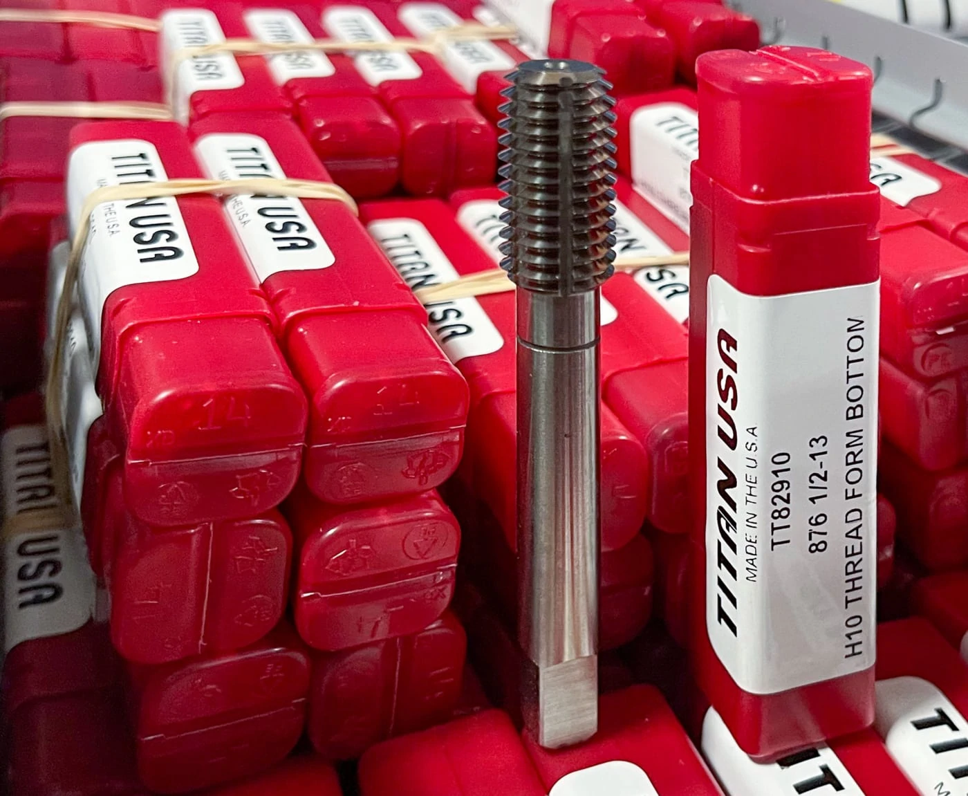
Yes Titan USA stocks STI Forming Taps as standards. Here is the link to the general purpose taps https://www.titancuttingtools.com/products/tapping/general-purpose-taps
The calculator will produce a recommended range of feed rates. Generally, it would be best if you started at the lower feed rate and slowly increase it from there. For an operation such as milling, the slower the feed rate (and cutting speed), the smoother the finish on the workpiece will be.
Eric, You have found what I believe is the greatest downside to thread form tapping. If all you ever do is run the machine that taps the hole it likely goes unnoticed but if you are involved in doing the assembly work that employs a formed thread where the tap drill / hole was slightly large you get what looks like a double helix. This apparent dbl. helix is the result of the thread crest being incomplete as there was insufficient material to upset and you actually end up with a slight trough or valley where the crest should be. The finer the thread the better roll taps work but if there is not enough material to complete the thread, they are a TERROR to assemble even for experienced operators.
Feed rate formula for turning
Thanks for the reply. My experience with roll tapped holes is on the user end only. I have never used a roll tap to thread a hole. The problem I was referring to was an improperly formed crest on the rolled thread. The displaced metal didn’t fully form into the crest but left, what looked like with an eye loupe, a second, smaller helical pattern on the incompletely formed crest. In the instance I’m primarily referring to, it even caused difficulty starting the screw. My guess as to why this happened is an oversized hole to start with leaving not enough metal to displace into the crest. Does this seem consistent with your experience in actually using roll taps to thread holes?
Let's go through an example of how to calculate speeds and feeds manually, using the speeds and feeds formulas discussed above. Your tool is half an inch in diameter and made of high-speed steel, and you are end-milling a block of aluminum. Looking up the average surface speed between the cutting tool and the aluminum, you find it to be 600 feet/min. Using the imperial speeds formula, you would perform the calculation:
Can thread forming taps be used to repair existing threads? Including threads in material that was powder coat painted after the original hole was taped.
Feeds and speedschart
Hi There, Excellent Blog, Thanks a lot for sharing about Thread Forming Taps. I have been looking for so long for this type of information. Keep Sharing….
Sign up to receive a monthly recap of: – The latest machining solutions – Machining tips and tricks – A recap of our most popular posts
Millingspeeds and feedsChart
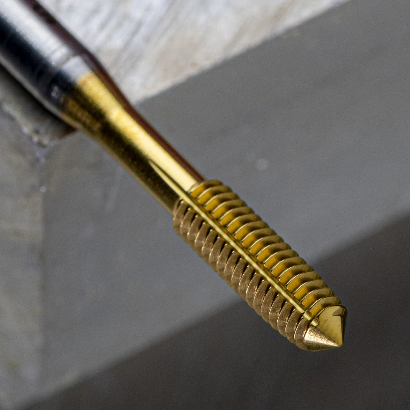
When using a Form Tap, chips are not formed, nor is any part material evacuated (Yes, you read that right). With thread forming, the tool is void of any flutes, as chip evacuation is not a concern. Form Taps quite literally mold the workpiece, rather than cut it, to produce threads. Material is displaced within a hole to make way for the threads being formed.
With the calculator mode set to manual mode, you need to enter the minimum and maximum surface speeds and chip loads. The specification sheet for the tool you are using may contain this data. Here's what you should do:
Cutting speed formula
Your article states: a ¼-20 roll tap requires a #1 drill size for 65% thread. What is a 65% thread ? Is a greater percent of thread possible or important ?
Ideally, you would also calculate the minimum and maximum speeds and feeds, so let's see how our calculator can work out everything for you in super-quick time.
All machine tool operations consist of a cutting tool (e.g., a drill bit) and the workpiece that is being machined to make something. So, if you're drilling a hole in a piece of wood, then the wood is the workpiece.
I learned quite a lot about thread-forming taps by reading this post. Thanks for publishing the post about unique facts of thread-forming taps. I will share the article with my colleagues.
Thread Forming Taps are incredibly efficient, as their tool life is substantial (Up to 20x longer than cutting taps), as they have no cutting edges to dull. Further, Thread Forms can be run at faster speeds (Up to 2x faster than Cutting Taps).
Next, enter the number of teeth the tool has to get the range of feed rates to use. The feed rates shown are for the average rotation speed. To calculate the feed rates at a different speed, enter the RPM into the custom rotation speed field. Similar to rotation speed, the slower the feed rate, the smoother the finish of the operation will be.
Looking to tap into fiberglass besides keeping tap cool and not use coolant. My plan is to use cooling air to keep tap cool. My question is being it’s a blind hole would it be best to form tap??? Tapped hole size being. 1 1/8-12 UNC-2B depth of thread is 1.250 deep.
Did you know that Thread Forming Taps require good lubrication? But why is that the case if chips are not being evacuated, and how does lubrication enter the part with such a limited area between the tool and the perimeter of the hole being threaded? Despite the fact that chips aren’t being formed or evacuated, cutting oils aid the Form Tap as it interacts with the part material, and reduces friction and heat generation. Lube vent grooves are narrow channels engineered into the side of Forming Taps that are designed to provide just enough room for lubricant to make its way into – and out of – a part.
As an example, a ¼-20 cut tap requires a #7 drill size for the starter hole, whereas a ¼-20 roll tap requires a #1 drill size for 65% thread.
With the tap drill formulas referenced (see below) … What “Class of fit” (Inch “H” value) (Metric “D” value) is this formula written for? If you have a low H or D the hole should be smaller. If you have a High H or D the hole should be larger.
1) the tap is programmed to go back into the same hole twice – leading to different start angles 2) (less likely) the tap is spinning within the collet during the tapping operation
Kennametalspeeds and feedschart
If you are using the metric system and have the surface speed VVV in meters per second and the diameter DDD in millimeters, the equation is:
Thread forming taps have no cutting and edge and do not produce chips. You should be able to chase an existing thread with this tool, although thread forming taps are not designed to remove burrs.
www.harveytool.com www.helicaltool.com www.micro100.com www.titancuttingtools.com www.corehog.com www.valorholemaking.com
Another interesting tidbit: A form tap may slightly raise (a couple thousandths of an inch) the area surrounding the top and bottom surfaces of the hole. A larger chamfer will help eliminate this raised area resulting a flatter, more even surface after form tapping. Or you can just stone or grind the surface after tapping if a larger chamfer is unacceptable.
The chip load depends on the characteristics of the tool and the workpiece material. For example, a tool drilling a hole into a soft workpiece material will have a higher chip load than a harder workpiece material.
Great question! The formula is for a standard tap, 1/4 – 20 H6 being the standard. For each H-limit above or below you would add or subtract .0005. For H7 it is +.0005, for H5 it is -.0005.
Physicist holding a 1st class degree and a member of the Institute of Physics. Creator of the UK vaccine queue calculator, and featured in many publications, including The Sun, Daily Mail, Express, and Independent. Tenacious in researching answers to questions and has an affection for coding. Hobbies include cycling, walking, and birdwatching. You can find him on Twitter @OmniSteve. See full profile
Drill Size = Major Diameter – [(0.0068 x desired % of thread) / Threads Per Inch]Drill Size (mm) = Major Diameter – [(0.0068 x desired % of thread x pitch (mm)]
If you are not sure how many teeth your tool has, look at it end-on and count how many sharp cutting edges there are around the circumference of the tool.
Feed rate formula for milling
These 8 unique facts about thread forming taps are very beneficial for us. Like cutting oils allow for reduced friction, how a simple formula can help you find the right drill size and the threads produced are stronger than conventional tapping threads.
Not all materials are well suited for Thread Forming Taps. In fact, attempting to use a tap in the wrong material can result in significant part and tool damage. The best materials for this unique type of operation include aluminum, brass, copper, 300 stainless steel, and leaded steel. In other words, any material that leaves a stringy chip is a good candidate for cold forming threads. Materials that leave a powdery chip, such as cast iron, are likely too brittle, resulting in ineffective, porous threads.
Continue reading to learn about machine tool operations and the two principal speeds and feeds formulas that power this calculator.
Thread forming produces much stronger threads than conventional tapping methods, due to the displacements of the grain of the metal in the workpiece. Further, cutting taps produce chips, which may interfere with the tapping process.
When selecting a Tap, you must be familiar with the following formula, which will help a machinist determine the proper drill size needed for creating the starter hole, before a Thread Forming Tap is used to finish the application:
Analyzing the equation, you might notice that π×D\pi \times Dπ×D is the formula for circumference of a circle. So we're dividing the speed at the circumference by the distance traveled during one rotation to get the number of rotations per minute.
Physicist at the Institute of Nuclear Physics in Kraków interested in magnetism and always ready to explain everything to everyone in simple terms. He is currently working on adding more scientific papers to his collection, accompanied by his son and another baby on its way. A perfectionist with an acute eye for detail, he has a unit converter in his brain and uses it to compare prices at the supermarket. Loves peace and quiet, especially during hiking. See full profile
Finally, it supports the turning operation where the cutting tool is stationary, and the workpiece rotates. This configuration is the essential operation of a lathe machine, which is used to create symmetric circular manufactured items.
The "speeds" part of the speeds and feeds calculator is the rotation speed of either the tool (e.g., for drilling) or the workpiece (e.g., for turning on a lathe). For a given tool and workpiece material, there is a range of recommended cutting or surface speeds between the two materials. Given the surface speed, you can calculate the spindle speed in revolutions per minute (RPM) using the following equation (when using imperial units):
Omni's speeds and feeds calculator helps you set the correct rotation speed and feed rate of your machine tool. It supports all of the following machine tool operations:
I’ve been programming for almost ten years, been using roll form taps for about 6 years and never once have seen a “double helix” from the minor diameter being oversize. Usually, a oversize minor dia. prior to tapping – will result in the pitch diameter and minor diameter being oversize after tapping (leading to the acceptance of a no-go thread gauge).
Drill Size = Major Diameter – [(0.0068 x desired % of thread) / Threads Per Inch] Drill Size (mm) = Major Diameter – [(0.0068 x desired % of thread x pitch (mm)]
Cutting speed chart
In preset mode, you can select the operation, tool material, size and number of teeth, and the workpiece material. The calculator contains a range of recommended cutting speeds for different materials, allowing it to calculate the rotation speeds. It also has the corresponding chip load data to calculate the feed rates.
Next, let's calculate the average feed rate at 4584 RPM4584\ \mathrm{RPM}4584 RPM, given that your tool has two teeth, and it has an average chip load when milling aluminum, which is 0.0040.0040.004 inches:
You will then see results for the range of speeds you should use. For the best outcome, start at the minimum speed and gradually increase it to the average figure. If you want a quick, but rough finish, carry on up to the maximum speed.
This would not be possible. Since you are reshaping the material and the material is now powdered coated, you will not have the required material to be able to form your new thread, and instead form your thread on the paint itself.
So it's a reamer speed and feeds, milling speeds and feeds, and drill feeds and speeds calculator (plus more) all rolled into one.
Use the preset mode to select from a range of tool and workpiece materials. Use custom mode if you know the surface speeds and chip loads.
A “double helix” condition could only be possible if the threads had multiple start angles. I’m not entirely positive why you would be noticing a “double helix” forming within your threads but my theories are
Are thread forming taps ok to use to chase threads in cast iron and aluminum? I am looking for something a bit better than thread chasers as far as quality.
Hello Eric. Yes that can happen, but it’s not really a problem of the forming taps. You could say forming taps require a tighter tolerance hole in that regard, but the hole should not be that much oversized anyway, even when using regular taps.
Great question! The percentage of thread refers to the percentage of height where basic thread height and external and internal threads are engaged. The percentage of thread is calculated by finding your total engaged length (EL) and your total overall length (OL). You then divide EL by OL and multiply by 100 to get your percentage, so your equation looks like this, Percentage of Thread = EL/OL*100. Some jobs require a certain thread percentage but if nothing is specified we suggest using between a 60%-75% thread percentage to help your tool last longer.
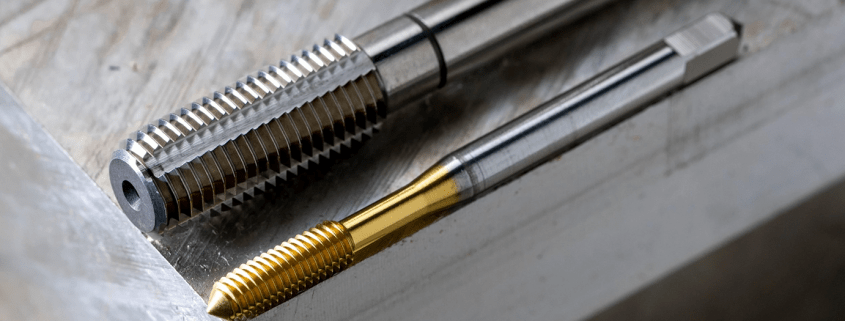
Unlike most CNC cutting tools, Thread Forming Taps, otherwise known as Form Taps, Forming Taps, or Roll Taps, work by molding the workpiece rather than cutting it. Because of this, Form Taps do not contain any flutes, as there is no cutting action taking place, nor are there any chips to evacuate. Below are 8 unique facts of Thread Forming Taps (and some may surprise you).
The term "feeds" refers to the feed rate or the relative linear speed between the tool and the workpiece. For example, for drilling, it is the speed at which the drill bit travels down into the workpiece material. The equation for the feed rate is:


 0086-813-8127573