
Riddle me this Pro-taper.... - Moto-Related - pro taper usa
NPTthread dimensions PDF
But if modeled threads are required you can create them using the Thread feature or the Stud Wizard feature (this is still a cosmetic thread) which was recently introduced to SOLIDWORKS. Here are some resources below you can reference at your convenience if you so desire.
NPTthread angle
National Pipe Thread Taper, commonly known just as NPT, is a U.S. standard for tapered threads used on threaded pipes and fittings. This standard is widely used all over North America. Pipe thread sizes are usually based on the inside diameter (ID) or flow size. The way to read an NPT size is the nominal inside diameter and the number of threads per inch. For example, if we have a 1/4-18 NPT, that means it is a 1/4 inch inside diameter and 18 threads per inch. If LH is added to the end, it means the pipe has a left-handed thread.
Thread Feature – https://help.solidworks.com/2024/english/SolidWorks/sldworks/c_thread_wizard.htm?id=c9372ae7ecdb4017a933e4aef6d6ac0d#Pg0

The next step is the End Condition which defines the total length of the thread, it can be left as the default value or customized to a specific distance. Another option that can be checked on is the cosmetic thread under the Options menu. It can be set to With or Without Thread Callout.
NPTthread full form
Creating Custom Thread Tool Profiles in Solidworks – https://support.hawkridgesys.com/hc/en-us/articles/4419921661197-Creating-Custom-Thread-Tool-Profiles-in-Solidworks
Thanks, but the title of this post is “creating NPT threads” which you have not done. You have created a callout for a thread.
NPTmeaning
For drilling tasks, we have a vast selection of twist bits, including split point, high-speed, and brad point bits. We also carry impact-rated drill bits, left-hand drill bits, screw extractor bits, and saw drill bits. Our woodboring bits are perfect for making precise holes in wood, while our masonry bits are ideal for concrete and brick.
Hi Nikki, the article is really helpfull and easy to understand. NPT standard actually is world wide used, no only for North american countries. But what about PT, Pipe Thread, used mostly in europe, is it possible make it in SolidWorks? and if is… can be made in inches and milimeters ?
For specialized tasks, we offer countersink drill bit sets, end mill sets, auger drill bits, and mortise and hinge bits. We also have a wide selection of hole saws and sets, including diamond grit, bi-metal, and carbon steel. Our abrasive attachments, such as cup brushes and abrasive wheels, are perfect for cleaning and sanding projects.
You’ll also find many Drill & Driver Bits products suitable for many DIY applications. All Harbor Freight Tools offer exceptional value, high-quality, and affordable prices.
If the With Thread Callout option is selected, the specific thread callout can be customized or left as default. Click OK to accept the Hole Wizard feature. In order to edit the callout, right-click and edit the Hole Thread feature embedded in the Hole Wizard feature.
I would recommend that you reach out to your local SOLIDWORKS Value Added Reseller (VAR) to see if they offer any consulting or mentoring services to help you with your sprinkler project.
At the bottom of the PropertyManager of the Hole Thread, the text can be edited to any note and can be later automatically imported in the 2D drawing of the model.
1/2nptthread dimensions in mm
NPTthread dimensions
The title of the post is “Creating NPT Threads in SOLIDWORKS Using the Hole Wizard Feature” (emphasis on Hole Wizard Feature). I get where you are coming from however I would make a comment.
Once we open up the Hole Wizard feature, select the Tapered Tap option in the Hole Type section. Set the standard to ANSI Inch, set Type to Tapered Tap Pipe Tap and in the hole specifications, select the desired size in inches.
Being from an area of Canada that is very heavily involved in the oil and gas industry, I end up talking about NPT fittings on a regular basis and I always get asked how to find the NPT thread in SOLIDWORKS. Luckily, the Hole Wizard feature inside of SOLIDWORKS already has the designated library of NPT sizes and we just need to look in the right place!
Npt threadingsizes
We generally wouldn’t recommend actually modeling those threads due to the performance degradation these small details can impart when used in larger assemblies, unless there is a need for the physically modeled threads (for example 3D Printing or FEA applications that require them) the call out it likely the best way to capture the details.
Good evening Madam. My name is Frederic FOE. I read your paper. And I am writing to ask your assistance. I am writing from Cameroon (Central Africa). I actually work on a M.Sc project aiming at improving a local model of agricultural sprinkler. The first task of my work will consist in producing a 3D printed model of my supposedly improved sprinkler. Then I will have to use Ansys Fluent to apply CFD on that model. As I don’t have any experience on neither 3D Printing or CFD, I need your help to advise me as I proceed. Would you help me review my 3D Model before I print It ? I am using Solidworks to Model the Sprinkler. I plan to use an online 3D printing Service and I don’t know which one to contact. Thanks for your assistance.
If there is no thread callout specified, another alternative can be used to show the NPT thread size on the drawing. Once the desired views have been added to the drawing, either use Model Items and check off Hole Callout or use the Hole Callout feature located in the Annotation tab of your drawing. The Hole Callout feature uses the geometry and information from the Hole Wizard to show the dimension. If the size of the thread is displayed with this method, you can notice in the example below, it displays the internal diameter of the through-hole as well as the NPT size.
NPTthread Chart
For any difficulty using this site with a screen reader or because of a disability, please contact us at 1-800-444-3353 or cs@harborfreight.com.
For more information on SOLIDWORKS tips or if you have any questions, contact us at Hawk Ridge Systems today. Thanks for reading!
1/8 in. - 3/4 in. #1 Titanium Step Drill Bit (13-Steps), #2 Titanium Step Drill Bit (6-Steps), and #3 Titanium Step Drill Bit (9-Steps)
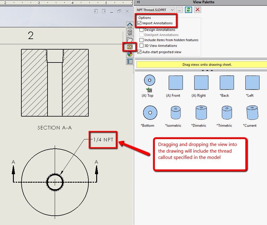
Once the 2D drawing is created, a view can be dropped into the drawing using the View Palette located in the Task Pane on the right-hand side of the user interface. With the option Import Annotations checked on, the thread callout mentioned above will show up with the view as it is dragged and dropped into the drawing.
Hello Nikki, I came across this article and however helpful, My SW2018 doesn’t have larger than 3″ in the Hole wizard for Pipe threads. I am faced with making an 5″ aluminum pipe Cap on the CNC Mill, that I am not able to find locally. and not sure how to draw this or program this when it comes to cutting the threads. I will be thread milling. Not sure what diameter, depth of thread, taper angle, and depth of the actual thread to program. I do know that 5″ is 8 TPI. So that part is clear. Any help appreciated. Thank you, Tryon
In the meantime, check out our other blogs/vlogs for more information on SOLIDWORKS Flow Simulation and 3D Printing. Here are a couple of links to get your started:
Drill and driver bits are essential tools for any carpenter, woodworker, or DIY enthusiast. At Harbor Freight Tools, we offer a wide selection of drill and driver bits to help you tackle any project with ease. Our driving and impact bits are designed to handle the toughest jobs and are available in a range of sizes and styles. We also offer quick-release bit holders, nut setters, and socket drivers to make your job easier.

Drill clean, straight holes every time with these 21 titanium drill bits from HERCULES™. The 135° StarterPoint™ limits walking for fast, straight holes, the variable helix flute clears material faster for better performance and the titanium coating improves performance, durability and stays sharper longer. Packed in a rugged high-impact heavy duty case that makes bit selection easy.


 0086-813-8127573