
Sandvik 6868346 TCMT Carbide Triangle Turning Insert - trianlge turning insert
On rectangular and parallelogram inserts, the width and length dimensions are used in place of the I.C. A two-digit number designates the sizes of these inserts. The first digit indicates the number of eighths of an inch in the width and the second digit indicates the number of fourths of an inch in the length of the insert.
Space provided behind the cutting edges to prevent rubbing. Sometimes called primary relief. Secondary relief provides additional space behind primary relief. Relief on end teeth is axial relief; relief on side teeth is peripheral relief.
1. Shape (e.g., A, C, D): 2. Clearance (e.g., A, B, C): 3. Tolerance Class (e.g., A, B, C): 4. Type (e.g., A, B, C): 5. Size Code: 6. Thickness Code: 7. Cutting-Point Configuration (e.g., 0, 0.5, A): 8. Edge Preparation (e.g., A, B, C): 9. Hand (R, L, N): 10. Facet Size: Decode Insert
ISOinsert chart
ANSI B212.4-2002 standard added one more capital letter O, which denotes other relief angles for new designs of indexable inserts.
Explanation: Enter each code position to decode the specific insert characteristics according to ANSI B212.4-2002 standards.
Insertnomenclaturechart
There are 16 standard shapes of indexable inserts, and each shape is identified by a capital letter as follows (Figure 1):
1. Shape2. Clearance3. Tolerance class4. Type5. Size6. Thickness7. Cutting-point configuration8. Edge preparation9. Hand10. Facet size
Millinginsertspecification
Find & Download Free Graphic Resources for Lathe Machine Vectors, Stock Photos & PSD files. ✓ Free for commercial use ✓ High Quality Images.
It will be a two-digit number carried to one decimal place when it is not a whole number: 1.2 – 5 ⁄ 32"; 1.5 – 3 ⁄ 16"; 1.8 – 7 ⁄ 32"; 2.5 – 5 ⁄ 16".
Inserts selection depends on workpiece material, chip control, surface finish, tool life, and the machine tool’s power and torque requirements. One of the commonly used indexable inserts for general turning is CNMG 432.
Carbide insertidentificationchartPDF
Replaceable tool that clamps into a tool body, drill, mill or other cutter body designed to accommodate inserts. Most inserts are made of cemented carbide. Often they are coated with a hard material. Other insert materials are ceramic, cermet, polycrystalline cubic boron nitride and polycrystalline diamond. The insert is used until dull, then indexed, or turned, to expose a fresh cutting edge. When the entire insert is dull, it is usually discarded. Some inserts can be resharpened.
2023121 — 304 Stainless Steel Machinability Chart ; Operations. Values ; Machinability. 40-45 % ; Turning. 550-600 SFM |160-180 m/min ; Milling. 300-330 SFM | ...
About the Authors: Edmund Isakov, Ph.D., is a consultant, writer, and frequent CTE contributor. He is the author of four books “Mechanical Properties of Work Materials” (Modern Machine Shop Publications, 2000); “Engineering Formulas for Metalcutting” (Industrial Press, 2004); “Cutting Data for Turning of Steel” (Industrial Press, 2009); “International System of Units (SI)” the CD-ROM (Industrial Press, 2013); and the software “Advanced Metalcutting Calculators” (Industrial Press, 2005). For more information, call (561) 369-4063, or email: edmundisakov9701@comcast.net. Shi ‘Steve’ Chen is Manager Product Engineering Turning at Kennametal Inc. For more information, call (724) 539-5321, or email: Shi.Chen@Kennametal.com
It is a two-digit number carried to one decimal place when it is not a whole number: 1.2 – 5 ⁄ 64"; 1.5 – 3 ⁄ 32"; 2.5 – 5 ⁄ 32"; 3.5 – 7 ⁄ 32".
2023810 — V · W · X · Y · Z · Resources · Fact ... Traditional medicine has a long history of contributing to conventional medicine and continues to hold ...
ISOinsertnomenclature pdf
The seventh position indicates the cutting point configuration: a radius or a facet. In the case of a radius, the number indicates how many of 1 ⁄ 64 of an inch in the radius: 0 – sharp corner (0.002" max. radius); 0.2 – 0.004"; 0.5 – 0.008"; 1 – 1 ⁄ 64"; 2 – 1 ⁄ 32"; 3 – 3 ⁄ 64"; 4 – 1 ⁄ 16"; 5 – 5 ⁄ 64"; 6 – 3 ⁄ 32"; 7 – 7 ⁄ 64"; 8 – 1 ⁄ 8"; 10 – 5 ⁄ 32"; 12 – 3 ⁄ 16" 14 – 7 ⁄ 32" = 14; 16 – 1 ⁄ 4"; X – Any other corner radius.
Tolerances on dimensions (± from nominal) are denoted by letters A, B and T. Dimension A is the nominal inscribed circle (I.C.) of the insert. Dimension T is the thickness of the insert. For pentagon, triangle and trigon shapes, dimension B is the insert height, i.e., the distance between one side and the opposite corner (Figure 2).
The fourth position is a capital letter denoting differences in design of insert, such as the existence of fixing holes, countersinks and special features on rake surfaces. There are 15 standard types in design as follows (Figure 3):
In case of a facet, two letters are used. The first letter designates the facet angle: A – 45°; D – 60°; E – 75°; G – 87°; P – 90°; Z – Any other facet angle. The second letter designates the facet clearance angle:
ANSIinsertnomenclature
Reel in your next saltwater trout with help from the Texas Rattlin' Rig Chatter Rattle Weights 2-Pack. Made of plastic, these weights feature a cylindrical ...
N7WR (2023 CIRRUS DESIGN CORP SR22T owned by SOUTHERN CARBIDE TECHNOLOGIES INC) aircraft registration information with aircraft photos, flight tracking, ...
For all other polygons, dimension B is the distance, measured along the bisector of the rounded off corner angle and a gage roll of nominal I.C. size tangent to the two sides opposite the corner (Figure 2). For example, if a tolerance letter is H, tolerances on dimensions (± from nominal) are: 0.0005" on dimension A, 0.0005" on dimension B and 0.001" on dimension T.
Nine relief angle values have been described in ANSI B212.12-1991 standard. These angles are the difference from 90° measured in a plane normal to the cutting edge generated by the angle between the flank and top surface of the insert. Each relief angle is denoted by a capital letter as follows:
TurninginsertIdentificationchart
Angle of inclination between the face of the cutting tool and the workpiece. If the face of the tool lies in a plane through the axis of the workpiece, the tool is said to have a neutral, or zero, rake. If the inclination of the tool face makes the cutting edge more acute than when the rake angle is zero, the rake is positive. If the inclination of the tool face makes the cutting edge less acute or more blunt than when the rake angle is zero, the rake is negative.
Workpiece is held in a chuck, mounted on a face plate or secured between centers and rotated while a cutting tool, normally a single-point tool, is fed into it along its periphery or across its end or face. Takes the form of straight turning (cutting along the periphery of the workpiece); taper turning (creating a taper); step turning (turning different-size diameters on the same work); chamfering (beveling an edge or shoulder); facing (cutting on an end); turning threads (usually external but can be internal); roughing (high-volume metal removal); and finishing (final light cuts). Performed on lathes, turning centers, chucking machines, automatic screw machines and similar machines.
American National Standard ANSI B212.4-2002 covers the identification system for indexable-type inserts for both single-point and multiple-point cutting tools. It was published on October 29, 2002. The earlier editions of the standard are:
Tool that cuts a sloped depression at the top of a hole to permit a screw head or other object to rest flush with the surface of the workpiece.
High-Speed Steel, or HSS, refers to a range of alloys. Usually, they are ferrous alloys of various metals, specifically vanadium, tungsten, molybdenum and the ...
Kegerator Kits · Beverage & Gas Tubing · Gas Cylinders · Shanks & Wall Kits · Shop All · Draft Parts · Dispensing Kits · 1-Tap · 2-Tap · 3-Tap · 4-Tap ...
There are 14 tolerance classes that control the indexability of the inserts. Each class is denoted by a capital letter. Letters for tolerances are A, B, C, D, E, F, G, H, J, K, L, M, U and N.
ISOcarbide Insert chart
According to ANSI B212.4-2002 standard, identification of the indexable insert includes 10 positions denoted by a capital letter. Each position (from 1 to 10) defines a characteristic of the insert in the following order:
The mathematical expression denoting one of several parameters that describe surface texture (same as average roughness Ra). Average roughness is the arithmetic average height deviation of the measured surface profile from the profile centerline. See surface texture.
Edmund Isakov, Ph.D., is a consultant, writer and frequent CTE contributor. He is the author of the books “Mechanical Properties of Work Materials” (Modern Machine Shop Publications, 2000); “Engineering Formulas for Metalcutting” (Industrial Press, 2004); “Cutting Data for Turning of Steel” (Industrial Press, 2009); the CD-ROM “International System of Units (SI)” (Industrial Press, 2012); and the software “Advanced Metalcutting Calculators” (Industrial Press, 2005). For more information, call (561) 369-4063 or visit www.edmundisakovphd.com.
Mar 11, 2015 — I'm drilling a hole to be tapped for a 1/4"-28, 1.5" deep. I'm using a #3 HSS drill bit, cutting mild steel. The hole has already been center drilled.
Dec 31, 2009 — 1. Rotate the outer dial so its arrow is 90 degrees to the target dial (According to which side you are on) 2. Input Torpedo Speed 3. Input Ship Speed 4. Read ...

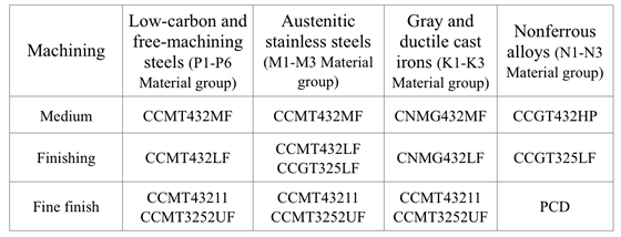
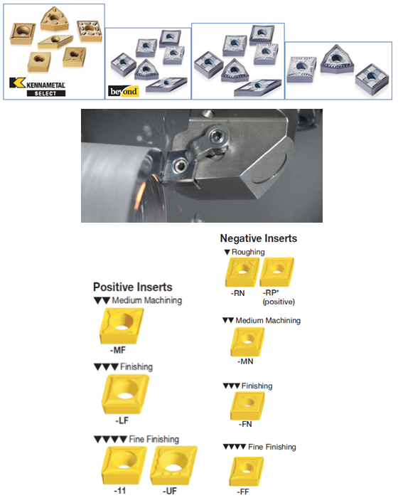
Due to the magazine’s space limitations, the authors provide the following tables showing most popular Kennametal’s indexable inserts only for general turning of steel, cast iron, and nonferrous alloys. These tables don’t cover all Kennametal chip breakers. (Figure 4 and Figure 5 also show Kennametal Inc. insert identification system and chip breaker identification system respectively.)
Imaginary circle that touches all sides of an insert. Used to establish size. Measurements are in fractions of an inch and describe the diameter of the circle.
Conditioning of the cutting edge, such as a honing or chamfering, to make it stronger and less susceptible to chipping. A chamfer is a bevel on the tool’s cutting edge; the angle is measured from the cutting face downward and generally varies from 25° to 45°. Honing is the process of rounding or blunting the cutting edge with abrasives, either manually or mechanically.
The 10th position is only used if there are letters in the seventh position. It will be a significant number representing the nominal sixty-fourths of an inch in length of the primary facet: 1 – 1 ⁄ 64"; 2 – 1 ⁄ 32"; 3 – 3 ⁄ 64"; 4 – 1 ⁄ 16"; 5 – 5 ⁄ 64"; 6 – 3 ⁄ 32"; 7 – 7 ⁄ 64"; 8 – 1 ⁄ 8"; 9 – 9 ⁄ 64"; 10 – 5 ⁄ 32".
Jun 10, 2020 — All menus shall either be single-use and disposed after each use, or sanitized after each use; Hand sanitizer shall be available at the host ...
Space provided behind a tool’s land or relief to prevent rubbing and subsequent premature deterioration of the tool. See land; relief.
The sixth position is a significant one- or two-digit number indicating the number of sixteenths of an inch in the thickness of the insert. It is a one-digit number when the number of sixteenths of an inch in the thickness is a whole number: 1 – 1 ⁄ 16"; 2 – 1 ⁄ 8"; 3 – 3 ⁄ 16"; 4 – 1 ⁄ 4"; 5 – 5 ⁄ 16"; 6 – 3 ⁄ 8"; 7 – 7 ⁄ 16"; 8 – 1 ⁄ 2"; 9 – 9 ⁄ 16"; 10 – 5 ⁄ 8".
The fifth position is a significant one- or two-digit number indicating the size of the inscribed circle (I.C.) for all inserts having a true I.C. such as Round, Square, Triangle, Trigon, Pentagon, Hexagon, Octagon, and Diamond. This position designates the number of eighths of an inch in the nominal size of the I.C. It will be a one-digit number when the number of eighths of an inch in the I.C. is a whole number: 1 – 1 ⁄ 8"; 2 – 1 ⁄ 4"; 3 – 3 ⁄ 8"; 4 – 1 ⁄ 2"; 5 – 5 ⁄ 8"; 6 – 3 ⁄ 4"; 7 – 7 ⁄ 8";


 0086-813-8127573