
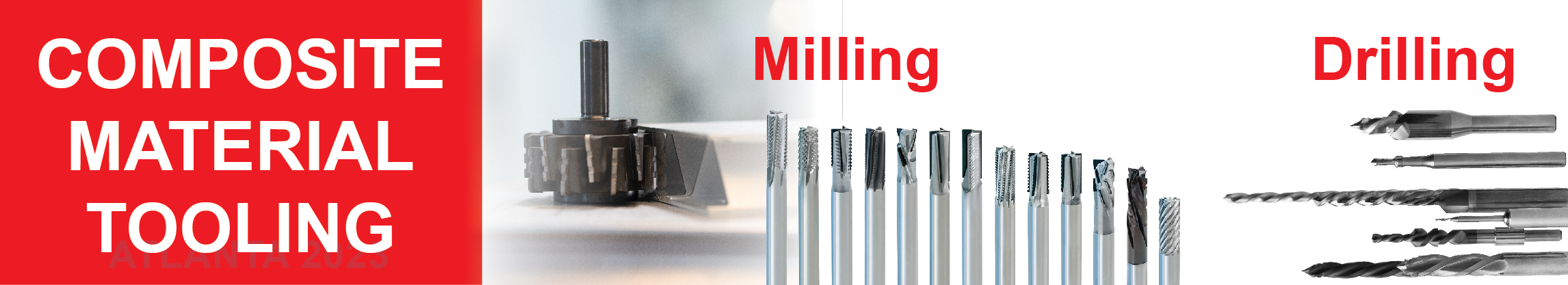
Shank Toolholders and Boring bars - boring bars for lathe
Dovetail Groove O’ring CSGroove Depth (L)Squeeze (%)Groove Width (G)Retainer Radius (R)Groove Radius (R₁) .070 ±.003.053 – .05523.057 – .061.005.015 .103 ±.003.081 – .08321.083 – .087.010.015 .139 ±.004.111 – .11320.113 – .117 .010.031 .210 ±.005.171 – .17318.171 – .175.015.031 .275 ±.006.231 – .23416.231 – .235.015.062 .375 ±.007.315 – .31916.315 – .319.020.093
What makes a saw blade a precision blade? it begins with the saw plate, i.e. the body. The larger the diameter of the saw blade, the more important the plate quality is. The tensioning of the saw body, which keeps it flat and running true is paramount to achieving a good finish and maintaining cut quality for the life of the saw blade. Once the plate is warped or “dished”, the chances of correcting the tension successfully diminish and the blade becomes useless. A quality saw plate will feature expansion slots that help reduce noise and disperse the heat created during cutting, allowing the plate to contract and expand as needed during the cutting cycle.
In a face seal, a dovetail and half-dovetail groove are ideal for holding an o’ring in place during installation and operation. This can allow more streamlined maintenance and shorter downtime with less effort required to secure the seal during installation. Especially handy if the face seal is assembled upside-down. However, due diligence is required when designing a dovetail groove due to limited void space compared to a conventional square groove. This problem can be aggravated by volume swell. Therefore dovetail grooves are not recommended unless end use conditions and their effects upon the seal are thoroughly taken into consideration.
A static triangular crush seal groove is a simple design and ideal when space is limited and/or wall thickness is too thin for a conventional groove. It achieves the same sealing efficiency with either internal or external pressure. However there is very little void space and volume swell can easily lead to extrusion failure. O’rings in triangular crush grooves are permanently deformed once installed, therefore cannot be reused and are discarded after use.
TCG Grind This saw blade tip geometry is a triple chip grind (TCG) commonly used to cut non-ferrous metals and composite materials such as laminated particleboard, MDF and other panel materials. If the material has a laminate both sides, then this design would not be the best choice unless the machine it is used on has a scoring saw unit that precuts the bottom of the panel when the blade exits the material. Note that one tooth has the corners chamfered, and the next tooth is a little lower and flat. They alternate in this manner around the circumference of the blade and this geometry serves to prevent chipping on the top surface finish (as well as the bottom when a scoring blade is used).
63RMS maximum: For non-critical sealing surfaces such as groove sides32RMS maximum: For static sealing on critical sealing surfaces such as groove base and top.16RMS maximum: For dynamic sealing surfaces and for sealing gases in a face type seal.
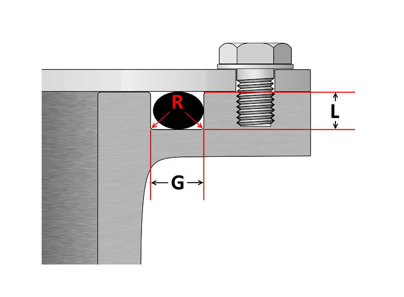
Note: Top radius (R) is a critical dimension; too small a radius can damage the seal during installation, while excess radius can lead to extrusion failure.
In summary, there are many factors that determine how well a saw blade will perform in the cutting process so if a saw is in use a lot, it is of utmost importance the right blade is on it in order to save money, improve efficiencies, quality and finish and reduce downtime. For more information on GUHDO saw blades, visit our website or contact us .
Micro Drill, for Stainless Steel from ATOM ➤ Order in many variants in the MISUMI online shop ➤ Free CAD data ✓ Fast delivery ✓ Fair prices ✓ Select and ...
Jun 1, 2024 — Climb milling can put a greater strain on the tool due to the pulling force exerted by the rotating tool. This can lead to tool deflection and affect ...
Groove Flange O’ring Cross Section(L) Groove DepthSqueeze (%)(G) Groove W Liquid ±0.005(G) Groove W Vacuum ±0.005(R) Groove Radius .070.050 – .05419–32.101 – .107.084 – .089.005 – .015 .103.074 – .08020–30.136 – .142.120 – .125.005 – .015 .139.101 – .10720–30.177 – .187.158 – .164.010 – .025 .210.152 – .16221–30.270 – .290.239 – .244.020 – .035 .275.201 – .21121–29.342 –.362.309 – .314.020 – .035
This article was featured in Cabinetmaker FDM (now Woodworkingnetwork) in Nov ’14. Here is the original text in its entirety:
Triangular Crush Groove Cross Section (W)±Groove Depth (L)± (-0) .070″±.003″0.092″+.003″ .103″±.003″0.136″+.005″ .139″±.004″0.184″+.007″ .210″±.005″0.277″+.010″ .275″±.006″0.363″+.015″ 1.50mm±0.08mm1.98mm+0.08mm 2.00mm±0.08mm2.64mm+0.08mm 2.50mm±0.08mm3.30mm+0.13mm 3.00mm±0.10mm3.96mm+0.13mm 4.00mm±0.13mm5.28mm+0.18mm 5.00mm±0.13mm6.61mm+0.25mm 6.00mm±0.15mm7.93mm+0.25mm 8.00mm±0.18mm10.57mm+0.38mm 9.00mm±0.18mm11.89mm+0.38mm
O’ring CSMinimum SqueezeGroove Width (G) .070 ±.003.005.080 .103 ±.003.006.110 .139 ±.004.007.160 .210 ±.005.008.240 .275 ±.006.010.315
Hollow Face Grind. This tooth style was developed specifically for cutting coated (laminated) panels on a table saw or vertical saw, to provide a clean cut on top and bottom of the panel when the machine it is used on does not have a scoring blade. The downside to a hollow face blade is that only very few saw sharpening companies have the ability to sharpen this blade properly. It requires a face grind (special rotary grinding attachment needed) every time the blade is sharpened or the performance will suffer.
Choose from our selection of chamfering drill bits, including over 2400 products in a wide range of styles and sizes. In stock and ready to ship.
Indexable gun drill with exceptional efficiency · 1. Wide range of options for various deep hole applications · 2. Ultimate efficiency Unique chip breaker and ...
As important as the o’ring seal itself is the groove that the o’ring seats into. The groove must be designed to accommodate not just the o’ring size, but also its intended usage; be it dynamic or static operation, radial or axial loading, vacuum or high pressure.
With the plethora of saw blades available in the market today, it can be daunting for the user to choose the right blade for the right application. Since Chinese-made blades have heavily infiltrated the wood products industry with low prices in recent years, it has become even more difficult to determine which blade is right. Low pricing can be very tempting! Visually, blades can be hard to differentiate since all are circular, they all have a hole in the center, and they all have teeth around the circumference – that’s about where the similarities end.
As an example, a modified ATB grind with a zero degree hook angle performs very well on solid surface material (such as Corian) and acrylics and looks like an ATB Blade with the points ground off and chamfered.
Dimensions apply to all laterally loaded o’rings in static face seal grooves for both liquid pressure and vacuum applications.
Metric O’ring Groove Dimensions O-Ring Cross Section(L) Cylinder Groove Depth(G) Cylinder Groove Width No Back Up Rings(G) Cylinder Groove Width One Back Up Ring(G) Cylinder Groove Width Two Back Up Rings(L) Flange Groove Depth(G) Flange Groove Width(R) Radius without back up ring(R) Radius with back up ring 1.00.81.4––0.651.40.20.2 1.20.951.7––0.81.70.20.2 1.31.051.8––0.91.80.20.2 1.51.22.1––1.02.10.20.2 1.61.32.2––1.12.20.30.2 1.9 & 2.01.652.53.95.31.42.50.50.2 2.42.03.24.66.01.73.20.50.3 2.52.13.44.86.21.83.40.50.3 2.62.253.65.06.41.93.60.60.3 2.72.33.75.16.51.953.70.60.3 3.02.53.95.36.72.23.90.80.3 3.152.74.05.46.82.34.00.80.4 3.53.14.86.27.62.74.81.00.4 4.03.55.47.18.83.15.41.00.4 4.54.06.07.79.43.46.01.00.4 5.04.36.78.410.13.96.71.00.4 5.54.87.39.010.74.47.31.20.6 5.75.07.79.411.14.67.71.20.6 6.05.38.29.911.64.88.21.20.6 6.355.68.710.412.15.18.71.20.6 6.55.78.910.612.35.48.91.20.6 7.06.19.512.014.55.89.51.50.6 7.56.514.412.915.46.210.41.50.6 8.07.011.013.516.06.611.01.50.6 8.47.511.714.216.76.911.72.00.6 9.07.812.515.017.57.412.52.00.6 9.58.313.315.818.37.813.32.00.6 10.08.713.516.018.58.313.52.00.6 11.09.615.518.020.59.115.53.00.6 12.010.516.819.321.810.316.83.00.6 14.012.219.021.524.011.619.03.00.6 15.013.220.022.525.012.520.03.00.6 16.014.021.524.026.513.521.53.00.6
ToolPro Professional Shadowline Ceiling Tile Cutter - Precision Ceiling, Drywall and Construction Edge Finishing Tool : Amazon.ca: Tools & Home Improvement.
EXTENDED REACH. This link to Extended reach software connect our foster/adoptive parents to complete their reports and documentations online and submit them ...
Round Cable Sheath Stripping Tool, for fast stripping and removal of sheath from power and copper/fibre telecom round cables to a depth of 4.75mm (3/16) ".

Due to PTFE’s (Teflon®) highly limited deflection ability, the following table has suggested groove dimensions for open face seal (flange) type grooves using imperial PTFE o’rings. PTFE o’rings in radially loaded closed grooves are generally not recommended, however if this is unavoidable, PTFE o’rings can be heated to around 100°C to allow them to become slightly flexible, aiding installation.
The above captures the most popular saw blade tooth geometries in the market. There are many more variations for specialty applications that make additional improvements to cutting performance for very specific materials, such as modification of hook/rake angle, clearance angles, gullet size, chip limiters, adding wiper slots etc.
Reciprocating Cylinder Grooves O’ring Cross Section(L) Groove DepthSqueeze %(E) Max Diametrical Clearance(G) Groove W 0 Back-up ±.005(G) Groove W 1 Back-up ±.005(G) Groove W 2 Back-ups ±.005(R) Groove RadiusMax Eccentricity .070.055 – .05715 – 25.004.095.140.207.005 – .015.002 .103.088 – .09010 – 17.005.142.173.240.005 – .015.002 .139.121 – .1239 – 16.006.1890.210.277.010 – .025.003 .210.185 – .1888 – 14.006.283.313.413.020 – .035.004 .275.237 – .24011 – 16.007.377.410 .540.020 – .035.005
Half Dovetail Groove O’ring CSGroove Depth (L)Squeeze (%)Groove Width (G)Retainer Radius (R)Groove Radius (R₁) .070 ±.003.053 – .05523.064 – .066.005.015 .103 ±.003.083 – .08519.095 – .097.010.015 .139 ±.004.113 – .11518.124 – .128.010.031 .210 ±.005.173 – .17617.190 – .193.015.031 .275 ±.006.234 – .23815.255 – .257.015.062 .375 ±.007.319 – .32314.350 – .358.020.093
The following information is a guide for o’ring groove dimensions for both static and reciprocating dynamic applications. The info is based on 70 Shore A Durometer hardness only.
For higher volume and demanding cutting applications, choosing the right blade will net a lower blade cost per panel cut, and will insure an accurate cut and good surface finish. Below are some of the more popular tooth geometries and their uses.
If you disable this cookie, we will not be able to save your preferences. This means that every time you visit this website you will need to enable or disable cookies again.
Jul 8, 2024 — Obviously, at a VERY quick glance, I thought they were making stainless steel tools (tops, etc.), but obviously they are not. What are your ...
Hi-ATB Grind. The Hi-angle ATB was developed as an alternative to the hollow face blade due to difficulties in getting a hollow face blade sharpened properly. The HI-ATB grind provides the same clean cut on the bottom of the panel when the blade exits the material, but this design too, has a down side. Due to the very aggressive cutting angle at the tip, the blade does not stay sharp as long as a standard ATB or TCG blade.
Tooth geometry, size and carbide grade utilized are also important to take a closer look at. The correct tooth geometry is essential to obtain the desired quality of finish on the product being cut – more about this in a minute. The size of the carbide tip will dictate how many times a blade can be sharpened so a smaller tip will typically be seen on a less expensive blade. (i.e. less carbide=lower cost) The grade of carbide being used is something that cannot be discerned by visual glance…and the difference can be quite startling between an industrial grade saw blade and one made for the do-it-yourself/retail market. Tungsten carbide is produced by binding hard carbide particles with metallic binders and the quality, binders and particle size used all play a role in the final cutting tip performance of a blade. Some carbide grades are far more suitable than others to machine, for instance, composite materials. The same applies to solid wood, softwood etc. A general purpose blade is, as its name implies, designed to take on any task and provide average results…it is not designed to maximize performance or finish.
GDP Industrial Tooling - German Designed Precision serving North American manufacturers with high quality, precision cutting tools and accessories under the GUHDO banner since 1986.
Are payouts delayed after you people have given things to you? Because my revenue never syncs with my pay outs at all.
ATB Grind The tooth design shown to the left is an alternate top bevel, ATB for short, and primarily used to cross-cut solid wood (hardwood and softwood), plywood, veneers, lattice and other homogeneous materials. The alternating tips, one left, one right around the entire blade circumference, provide the best surface when cutting wood in the opposite direction of the grain. Some specialty rip saw blades feature this ATB design as well, however, they will have deeper gullets (the “valley” between the teeth) to insure that the chips evacuate the cut and don’t generate heat.
Static Cylinder Grooves O’ring Cross Section(L) Groove Depth Radial(L) Groove Depth AxialSqueeze Radial %Squeeze Axial %(E) Max Diametrical ClearanceG) Groove W 0 Back-up ±.005G) Groove W 1 Back-up ±.005G) Groove W 2 Back-ups ±.005R) Groove RadiusMax Eccentricity .070.050 – .052.050 – .05422–3219–32.004.095.140.207.005 – .015.002 .103.081 – .083.074 – .08017–2420–30.005.142.173.240.005 – .015.002 .139.111 – .113.101 – .10716–2320–30.006.189.210.277.010 – .025.003 .210.170 – .173.152 – .16215–2121–30.006.283.313.413.020 – .035.004 .275.226 – .228.201 – .21115–2021–29.007.377.410.540.020 – .035.005
Flat Grind This blade with flat top teeth is designed for ripping solid wood. A rip cut is simply a parting cut that is made in the same direction, i.e. parallel to the grain of the wood. This particular design, with the “hump” on the shoulder behind the tooth, (the technical term is “chip limitor”) is to help reduce the chances of material kick-back……here’s a great explanation of this phenomenon.
Black and Gold Yellow Color Finished Rolled Forged HSS Drill Bit for Metal ; Material, HSS (HSS Cobalt is Available) ; Process, Rolled (Fully Ground, Rolled & ...
This website uses cookies so that we can provide you with the best user experience possible. Cookie information is stored in your browser and performs functions such as recognising you when you return to our website and helping our team to understand which sections of the website you find most interesting and useful.


 0086-813-8127573