
Shop Tools products - tools corner
Sometimes, for ease of assembly, it may be necessary to tighten or loosen the fastener. Usually, a socket wrench is used for the purpose, which means enough space must be available around the screw head to insert the socket wrench and allow it to grip the head of the fastener. For this, the counterbore cavity is drilled to a diameter larger than that necessary to accommodate the socket wrench.
Counterbore vs countersink
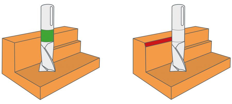
In downcut milling, the end mill pulls itself into the workpiece, which can lead to the gantry or the Z-axis beeing pulled uncontrolled (backlash of lead screw) in the direction of the workpiece during the removal of larger chips. This causes a less precise milling pattern and can even result in the breakage of the end mill, if the chip building is too large.Assuming backlash-free ball screws are used, the downcut is preferred over the upcut milling.
Counterbore hole symbol
Example calculation for aluminum (wrought alloy) with 8 mm end mill 2-flute: n = 19904 rpm from upper formula fz = 0,064 from chart z = 2
Countersink hole
While countersinking creates a conical cavity that matches the angled shape of the underside of a flathead screw, counterboring creates a flat-bottom cavity. This allows the head of the screw or bolt, often used with a washer, and its flat underside to rest totally within the counterbore. Often, a deeply set flathead screw will usually have a cavity that is about the same size as the head of the screw. However, the cavity meant for a counterbore is somewhat larger than the head. This allows room not only for a washer, but for the driving tool as well, such as a socket wrench.
Suitability of lubrication system for cutting materialsCu AlloyAl Casting AlloySteel ferriticMg AlloyWrought Aluminum AlloyPearliticCast IronStainless Steels
The maximum possible infeed is usually reduced to the spiral length of the end mill, otherwise the shank will rub on the workpiece. Due to the relief-grinded shank, depths over several infeeds up to the maximum effective lengths are possible, thus, exceeding the spiral length.
Counterbore hole dimensions
*The stated cutting speeds are average values. In result of the milling process and the type of end mill adjustments might be necessary .Roughing: Reduction of up to 25 % – Finishing: Increase of up to 25 % – HSS end mill: Reduction of up to 50 % (hard materials) – VHM end mill: Increase of up to 25 %
To avoid increasing vibration of the end mill, we recommend clamping the bit as short as possible or as long as necessary.
The process of counterboring creates a cylindrical cavity with a larger diameter at the head of a pre-drilled hole. The pre-drilled hole is meant to contain the fastener and to prevent the two work pieces from separating when their two flat surfaces are joined. The larger cavity matches at least the width and depth of the head of the fastener. This cavity is called the counterbore.
Counterbore Bit
If the maximum speed of the milling motor is lower than the calculated value, the maximum speed of the milling motor needs to be inserted into the formula for the feed calculation.
The counterbore tool is typically a specialized drill bit that creates the hole for the body of the fastener and the larger sized cavity for its head, both at the same time. Usually, the fastener chosen is a flat-bottomed screw such as a round head or a pan head screw. The counterbore tool typically has two cutting radii – one to create the pre-drilled hole, and the other for creating the recessed cavity in the workpiece.
Spotface vs counterbore
By using a counterbore, the manufacturer has an opportunity for hiding the fastener completely during the joining process. The fastener can be made to lie either flush with or below the surface of the workpiece such that the head does not hinder the design. While working with wood, increasing the depth of the counterbore beyond the thickness of the fastener head means there is room for a wooden plug to be fixed in the extra space. That completely conceals the fastener and provides a continuous wood surface.
Acrylic glass, wood, carbon or plastics – each material must be processed with a suitable end mill for the result to look as good as the idea. In addition, the speed and feed rate need to be adjusted accordingly. You will quickly gather your own empirical values, but there are also specific formulas for calculating the speed rate and other values. The easiest way is to use the free STEPCRAFT Milling Calculator. You can find it in the App Store and the Play Store. Simply select your machine, your material and your end mill and the STEPCRAFT Milling Calculator will show you the appropriate speed rate and cutting data in no time.
Counterboring Tool
During contour milling, we recommend a lateral infeed of approx. 25 % of the end mill diameter while applying 100 % immersion depth.The immersion depth is conditional to the milling motor, the structure and the stability of the machine. This means a reduction of the values is required, when using a less powerful and / or lighter milling motor.
With a drill, you can do different types of things with metals and non-metals such as wood and plastic. Such things include drilling a hole, boring or making the hole bigger in diameter and countersinking and/or a counterboring to allow a screw, bolt or fastener sit flush with the workpiece.
Manufacturers often hide the fasteners used in the joining process. One of the methods they use for doing so is a counterbore. In practice, the word counterbore is used interchangeably for the process, for the specific tool and for the cavity itself. The process makes a specially shaped cavity that hides not only the entire length of the shaft of the fastener, but the head of the fastener as well. As explained earlier, counterboring differs from countersinking principally in the shape of the cavity – it is cylindrical rather than conical as for countersinking.
The cooling of non-ferrous metals occurs in best case with a lubrication system in combination with lubricant. Furthermore, the lubricating improves the surface quality and the service life of the tool. Lubricating with soap solution is suitable on acrylic glass. This improves an excellent surface.
During upcut milling, the end mill pushes away from the workpiece, which, when only removing little chips, quickly causes the cutting edge to push out of the workpiece. This leads to chatter marks which create an unclean surface and reduce the endurance of the end mill.The upcut milling is favored on machines with threaded lead screws which contain backlash.


 0086-813-8127573