
Spade Drill Bits (Flat Drill Bits) for Wood | Bosch DeWalt ... - drill bit flat
How to cuta square holein Fusion 360
Carbide has also shown to be an efficient neutron reflector in several applications. This robust substance was also employed during the early research into nuclear chain reactions, notably for the protection of weapons during those early studies. Although the usage of carbide in this business is not quite as prevalent as it may be in some of the others, it is very essential that anybody working with any kind of material do so in the most careful manner possible..
For example, if I just wanted the outer perimeter of these three shapes…then with the trim tool active I’ll simply click and while holding down the left mouse button I can drag through all of the different lines that I want to trim away… and I’m doing this a little bit slow on purpose so you can see what I’m doing, but be aware that you can actually drag through sketch geometry pretty fast here.
Not only does it completely relieve the internal tension of the substrate, but it also removes the unevenly high edges of the carbide inserts, which means that the continuity and consistency of the edge of each carbide insert is substantially improved. The state-of-the-art sandblasting and grinding equipment that are equipped with the pre-coating treatment method that was created by our company make this accomplishment feasible.
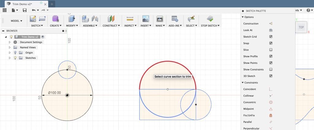
Before I trim this other line(keyboard shortcut “L”) Creates lines and arcs. Select a start and endpoint to define a line segment. Click and drag the endpoint of a segment to define an arc. away, I want you to take notice of the sketch constraints that are present. I’m going to hit the escape key on my keyboard so I can click on the outer circle. You’ll notice there are a few coincident constraints, and if I click on the smaller circle it also has some coincident sketch constraints, all of which were automatically applied when I created this sketch geometry.
After the insert has had its thickness reduced to the proper level, it is subjected to further grinding in order to create the ideal form and dimensions for it. Higher standards, both in terms of performance and stability, have been imposed on cutting tools in order to meet the needs of contemporary high-speed cutting and automated machine tools. In particular, coated tools have to go through the process of passivation before they can be coated. This is done to guarantee that the coating will be durable and will last for a long time. The objective of the edge passivation technology is to solve the issue of the micro notch defect that is left on the edge of the carbide inserts after grinding, to reduce or eliminate the edge value, and to achieve the objective of making the edge smooth, sharp, and durable.
For the second demo, you’ll see that I have some sketch geometry that has a number of different lines on the inside. A simple trick with the trim tool that is often overlooked, is the fact that you can drag through multiple lines to quickly trim things away.
Carbide is more brittle than other standard tool materials, making it more subject to chipping and breaking, in addition to being more costly per unit than other typical tool materials. Because of these drawbacks, the carbide cutting tip itself is sometimes designed in the form of a tiny insert that is intended to be used in conjunction with a larger cutting tip on a tool whose shank is constructed from a different material, most frequently carbon tool steel. This provides the advantage of employing carbide at the cutting interface without the high expense and brittleness that would be associated with manufacturing the complete tool out of carbide. Carbide inserts are used in the majority of contemporary face mills, in addition to numerous lathe tools and end mills.
The reason I pointed out those coincident constraints before using the trim tool was to make you aware of this fact that any time you use the trim tool you’ll have to be cautious of what it does to your constraints and dimensions. If this warning message ever comes up you can always hit the undoReverses the effects or results of the most recent action. button to take notice what constraints or dimensions you have and then you can hit the forward or redoRe-applies the most recent action that was undone. button to reapply the trim tool.
Fusion 360split body for printing
For this third demo, you’ll notice I have a splineCreates a spline curve through the selected points. Select the first point to start the spline. Select additional points as fit points. that runs through some other sketch geometry. One common misconception is that the trim tool will trim away the line up until the next spline pointCreates a sketch point.. Unfortunately, that is not the case. You’ll notice as I hover over the spline that it works like all sketch geometry, where it trims the line at the next intersection of sketch geometry.
Tungsten carbide is one of the most often used instruments because it is both precise and long-lasting, two qualities that are essential for a variety of medical operations. One of the most noteworthy applications for carbide is in surgical instruments. Tungsten carbide is used to manufacture the tip of the blade of the tool as well as the end of the utensil, despite the fact that the base of the tool itself is normally fashioned from titanium or stainless steel.
After sintering, the sizes are checked using the following criteria: A micrometer will be used to measure the dimensions, and an additional test for roundness will be performed on carbide rods.
In this first example, you’ll see that I have two circles that overlap. If I click and selectThe selection mode controls how objects are select when you drag in the canvas. each section, you’ll see that each section turns blue where I have a closed profile shape. So technically, there are 3 different closed profiles here that I could extrudeAdds depth to a closed sketch profile or planar face. Select the profile or planar face then specify the distance to extrude.. However, all I want is this main profile or the largest one that I have selected. With the trim tool active, you’ll see that as I hover over sketch geometry it will highlight in red which part will be trimmed or cut away.
When doing quality control on the raw materials, it is necessary to make use of a carbon-sulfur analyzer. This is done to ensure that the tungsten carbide powder has an adequate amount of both carbon and Sulphur.
When one of the insert’s cutting edges is worn, it may be turned to a fresh, unused edge for shapes that are triangular, square, rectangular, diamond, rhombic, pentagon, and octagon. Other shapes that have multiple cutting edges include octagon, pentagon, and rhombic. Other forms, such as rhombuses, pentagons, and octagons, also contain many angles that may be used for cutting. These inserts have a variety of applications, including turning, boring, drilling, and grooving, to name a few of them. You may get more use out of an insert by utilizing its worn edges for roughing applications before rotating it to a fresh edge and using it for final machining. This will allow you to get more life out of the insert.
Fusion 360 cutbody with sketch
The last demo geometry that I’ve set up is created with a number of different pieces of sketch geometry. Now technically there’s nothing wrong with leaving the sketch geometry how it is…but often times you’ll find it’s best to trim away unnecessary sketch geometry, which makes it easier to use the modeling commands, such as the extrude or loftCreates a transitional shape between two or more sketch profiles or planar faces. Select a series of profiles or planar faces to define a shape. Optionally select rails or a centerline to guide the shape. commands.
After the sintering process, the material is examined using a variety of tools, including the following: Conduct tests to determine the TRS of the carbide rod, as well as its microstructure, cobalt concentration, and the material’s hardness. Include a dropping test to confirm that there is no flaw in the material in the centre or inside of the blank. Additionally, include an ultrasonic scanner for carbide die blanks to check that there is no sand hole inside the blank.
I’ll right-click and select “Repeat Trim” from the marking-menu. This time, I’ll click on the top of the large circle, to trim it away. If you look in the lower right-hand corner you’ll notice there’s a warning that some constraints and or dimensions may have been removed.
The trim command can be activated from the sketch dropdown list… or from the right-click sketch menu. You’ll also be able to activate the trim command with the keyboard shortcut letter “T,” as in Tango, as the trim command is used quite often while in the sketch environment.
If the red preview looks correct, then all you have to do is click on the geometry once, and it will be trimmed away. I’ll click once on the top of the smaller circle. After trimming some sketch geometry the trim tool remains active, so you can continue to trim away other parts of the sketch.
How to cutan objectinhalfin Fusion 360
After yet another visit to the lab for a quality check, the top and bottom of the insert are ground to the right thickness. This completes the manufacturing process. The stage that we are now at is called the semi-inspection. Grinding cemented carbide, which is the hardest material that humans have ever discovered, needs industrial diamond, which is the hardest mineral that exists on any planet.
To get started, the material is put through a press that is highly automated, CNC controlled, and equipped with punches and dies so that it may be pressed into the necessary basic shape and size. The inserts, after being pressed, have a look that is quite similar to that of a true carbide insert; nevertheless, their hardness is not even close to meeting the requirements. Imported press machines and high-precision moulding machines, along with homogeneous spray powder, ensure that the density of the substrate body is comparable with the density of the clearance as well as the cutting edge of carbide inserts. This is accomplished by ensuring that the density of the substrate body is the same as that of the clearance. The grind value is delicately adjusted so that the whole surface and cutting edge are constant, as well as the tool’s durability and duration of use. This is done so that the tool may be used for a longer period of time.
Fusion 360 cutbody with another body
In addition, carbide recycling materials such as carbide inserts may be used to a wide variety of purposes, which makes these materials an important component for a lot of different companies. Let’s take a more in-depth look, shall we?

Once the inserts have been machined, the next step is for them to be cleaned, and then they are shipped to be coated. When working with the inserts at this stage, it is imperative that protective gloves be used so that no oil or dust gets on the hands. They are given a coating after first being positioned into fixtures that are fastened to a carousel and then being placed within an oven that maintains a low pressure. This is the component of the insert that is responsible for giving it its unique color.
The following phase in the process, which comes after the insert has achieved the necessary amount of hardness, is to bring it to a point where it can be delivered to the customer. Before going on to the next step of manufacture, we will first use the coordinate measuring equipment to do a comprehensive check to confirm that the size of the insert satisfies all of the parameters. This will be done before we move on to the next stage.
In summary, the trim tool is used to clean up and refine geometry without having to re-sketch entire sections. Trimming sketch entities is not critical to creating 3-dimensional features, however trimming extra sketch geometry will make the sketch more robust and clearly defined.
© 2020-2024 Kennedy Enterprises, LLC dba Product Design Online, Woodinville, WA. All Rights Reserved. All content on ProductDesignOnline.com is subject to the License Agreement. Redistribution of content on this site is strictly prohibited. Affiliate Program Accessibility Statement Cookie Policy Disclaimer Privacy Policy Terms of Use Mission: Making CAD education accessible to anyone, anywhere.
Carbide gives materials a high hot hardness in addition to a remarkable wear resistance when used in their construction. Carbide inserts are a superior option than high-speed steel when it comes to durability, making them a good pick for use in applications that require cutting metal. Coatings that provide additional resistance to wear, such as titanium nitride (TiN), titanium carbonitride (TiCN), titanium aluminum nitride (TiAlN), and aluminum titanium nitride (AlTiN), may lengthen the life of inserts by a significant amount. Examples of these coatings include titanium nitride (TiN), titanium carbonitride (TiCN), titanium aluminium nitride
Following the completion of the final inspection, each insert is checked against the blueprints and the batch order to ensure that it meets the standards. After that, you may finally start packing it. After having the proper grade laser-etched into the insert, it is then placed in a grey box that has a printed label affixed to it. Finally, the insert is given its final presentation. It is now ready to be distributed to the many customers who purchased it. On the insert box, you’ll find not only information about the product, but also the date, as well as the serial number.
With the trim tool active, I’ll click and drag over all the inner geometry that I don’t want. I’ll click and drag over each corner… releasing with my mouse as I move to the next, ensuring that I don’t accidentally trim the geometry I want to keep… and then I’ll trim away the sketch geometry of this inner part.
The absolute best raw material consists of a very fine spherical powder formed of cobalt, in addition to other compounds that have an extremely high level of purity. It is possible for each batch of powder to preserve its homogeneity and consistency throughout the production process by using the most cutting-edge mixing and wet milling technologies, in conjunction with accurate calculation.
In order to get the desired result of increased brittleness, the insert is subjected to a heat treatment that lasts for 15 hours and is carried out at a temperature of 1500 degrees Celsius. Sintering is the process by which the molten cobalt and tungsten carbide particles are brought together and bonded together. First, the insert goes through a significant shrinkage, and this shrinkage must be precise in order to achieve the appropriate tolerance; second, the powder mixture is transformed into a new metallic material that is known as cemented carbide. The treatment process that takes place in the sintering furnace accomplishes two goals. The cobalt magnetic pole tolerance on the inside of the sintering furnace is guaranteed to be within 0.3, and the magnetic force is guaranteed to be within 0.5. Neither of these parameters may be outside of their respective ranges. Carbide inserts that are manufactured using a large number of batches have remarkable stability. This is because even the smallest amount of variation is sufficient to minimise the quality variation of each batch to a minimum as much as is humanly feasible.
Carbide inserts are manufactured in a large number of distinct geometric forms, each of which is customised specifically to each certain application in order for them to be able to carry out the various cutting processes. Carbide inserts are used in a variety of industries, including automotive, aerospace, and construction.
How to cuta sketchin Fusion 360
Before adding gaseous chloride and oxide, as well as methane and hydrogen, the insert has to be positioned within the furnace in the event that the coating procedure involves the CVD approach. These gases interact with one another and also take action on the surface of the cemented carbide to generate the insert when the temperature reaches one thousand degrees Celsius. You will wind up with an even coating that is no thicker than a few thousandths of a millimeter at most. This will be the result of your efforts. The value of some coated inserts goes up because the surface is given a golden finish. In addition, the lifespan of the coated inserts is much longer than that of the untreated inserts by a factor of five. PVD is sprayed onto the insert while it is heated at a temperature of 400 degrees Celsius.
Fusion 360 cutbody with plane
After being sintered, the material is subjected to a manual examination, which it must pass. Carburization and decarburization, sand holes in the surface, and tiny fissures are some of the things that should be looked for while doing a visual inspection of the material to determine whether or not it is flawed.
Carbide inserts are virtually certain to have been used at some stage in the careers of all those who have done work with machines that cut metal. Inserts made of carbide for cutting tools are a product that cannot be overlooked in the metal cutting tool sector. Boring, turning, cutting, drilling, grooving, hobbing, milling, and threading are just some of the many applications that make use of them.
Again, you’ll notice the part in red shows that it will trim the sketch geometry up until the sketch geometry it intersects.
Carbide inserts manufacturers like HUANA are able to fulfil the demands for ever-increasing feeds and speeds, as well as the need for longer tool life and reduced costs, by continuously refining the designs of tungsten carbide inserts and creating better and better coating methods. As one of the leading manufacturers of carbide inserts, HUANA offers the best cutting tool solution for almost any application or machining process. With a variety of inserts and insert configurations that have been designed specifically for different metals, such as steels, stainless steel, cast iron, and aluminum alloy, HUANA is able to cater to a wide range of cutting needs. Whether you are roughing, grooving, finishing, or doing any of the various forms of machining. Due to the extensive variety of carbide insert goods and solutions that we provide, we are certain that you will find exactly what you are looking for.
How toextrudecut in Fusion 360
Chemical vapour deposition, often known as CVD, and physical vapour deposition are the names of the two methods that are used to coat objects in today’s world (PVD). The nature of the material and the processing procedure come into play when deciding which coating method to use. The thickness of the coating is going to be determined by the application of the insert, and the thickness of the coating is going to have an effect on the durability and the life of the insert. The surface of the cemented carbide is coated with a number of very thin coatings, including as titanium carbide, aluminum oxide, and titanium nitride. These coatings have the potential to considerably prolong the material’s service life and durability. The fact that there are a lot of coatings is the closely guarded technical secret behind this.
Carbide is an excellent material for jewelers all over the world to use, not just for the shape of jewelry but also for the jeweler itself. Tungsten is an excellent material for wedding rings and other types of jeweler because of its high level of hardness, which places it just slightly below that of diamonds. In addition, jewelers have to depend on effective tools in order to work on these items, and carbide is an excellent material for that purpose. What’s not to like about tungsten jeweler, since it has a great appearance, is highly durable, and is often less expensive than gold?
Inserts that are round or circular may be used for button milling, in addition to turning and splitting radius grooves. This is because of their versatility. Copy cutters, which are often referred to as button mills, are machines that make use of circular inserts that have a radiuses edge to a significant degree. Because of this, better feed rates and deeper cuts may be performed while consuming a much reduced amount of electricity. The transformation of radial grooves into a round component is referred to as “radius groove turning,” and the method is named after the term. Parting is the process of cutting through a section in its entirety, and the term refers to both the procedure and the result.
For this demo, I’ve gone ahead and set up some sketch geometry, which I’ll use to showcase how the trim tool works. If you’d like to follow along – I’ve put a link to the demo file in the video description below.

Utilizing a spiral spray dryer tower allows for the powder to have an exceptional fluidity, which, in turn, leads to a density that is consistent throughout the carbide inserts blanks. This is the end product of the process. Our fixed tower, which is only committed to defined tasks, avoids any mixing of grains of varied sizes within a batch. This helps to ensure that the uniformity and high quality of each and every substrat is maintained throughout the production process.
Carbide insert wear that is visible in woodcutting is caused, in great part, by chemical corrosion with the cobalt binder of the carbide (glue). Because of this, the tough tungsten particles are able to leach away, which results in a blunting of the cutting edge.
Diamonds are used in the grinding process so that the carbide insert will ultimately have the correct shape after the operation is finished. In order for the inserts to be of a quality that is commensurate with the requirements imposed by the geometric angles, they are ground using a variety of techniques. Throughout the process of grinding, the insert is subjected to checks and measurements by the grinder’s built-in measuring control at a number of different places.
The insert grade that you employ may make all the difference in the world when it comes to how productive your manufacturing process is, and this is true regardless of the size, material, or design of the component. You may keep ahead of the competition by choosing the appropriate insert for the particular machining process you will be doing. Inserts are an essential part of the metal cutting process and cannot be imagined without them. The inserts themselves are crafted from some of the most abrasive substances that can be found anywhere in the globe.
The nanotubes are reduced to an extremely fine powder by a process known as ball milling, which is a kind of grinding. This operation is also known as milling. During the process of ball milling, a localised high pressure will be formed as a consequence of the collision between the tiny hard balls that are enclosed in a concealed container. This collision will take place within the mill.


 0086-813-8127573