
Strap in, recycled carbon fibre is just the start - recycled carbon fiber
2024615 — Work hardening is the process of strengthening a metal by subjecting it to plastic deformation. This deformation causes the metal to become ...
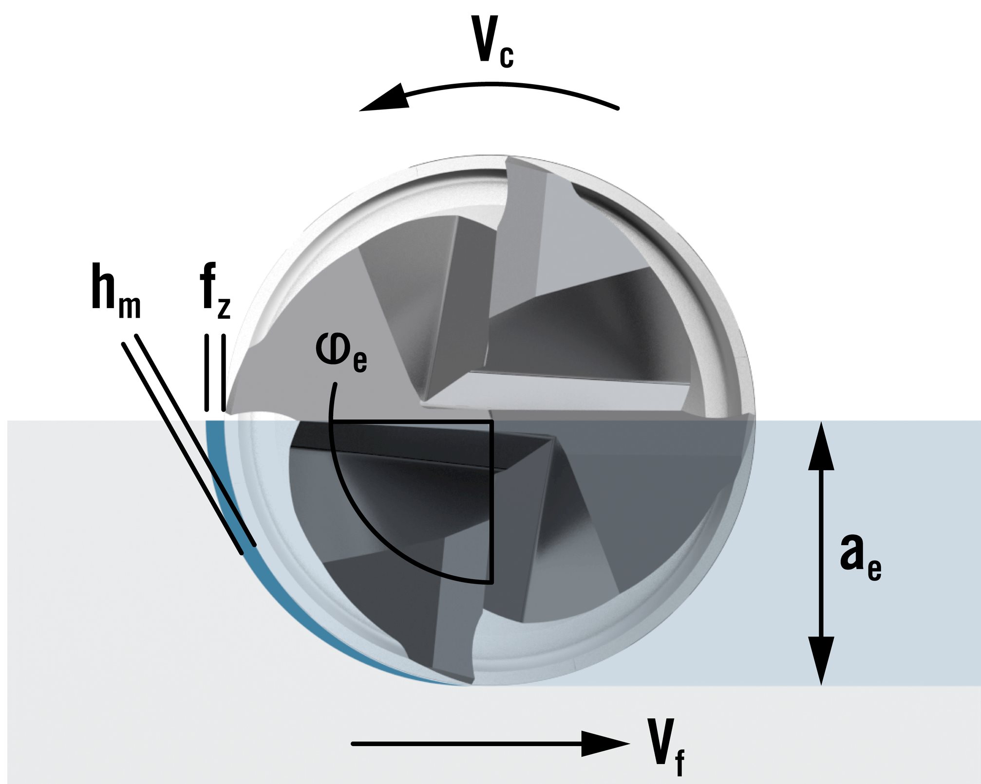
If the ae drops (ae < 0,5xDc) to, for example, 1 mm (10 percent), then average chip thickness will become smaller, allowing for faster roughing by applying increased feed per tooth (fz). While the cutter removes less material, it does so at a much faster pace.Also, there is less tool and machine spindle strain generated when compared to taking heavier radial cuts at slower feed rates. In dynamic milling roughing applications, a lower AEMX (radial depth of cut) also allows for an increased APMX (axial depth of cut) for even faster material removal.
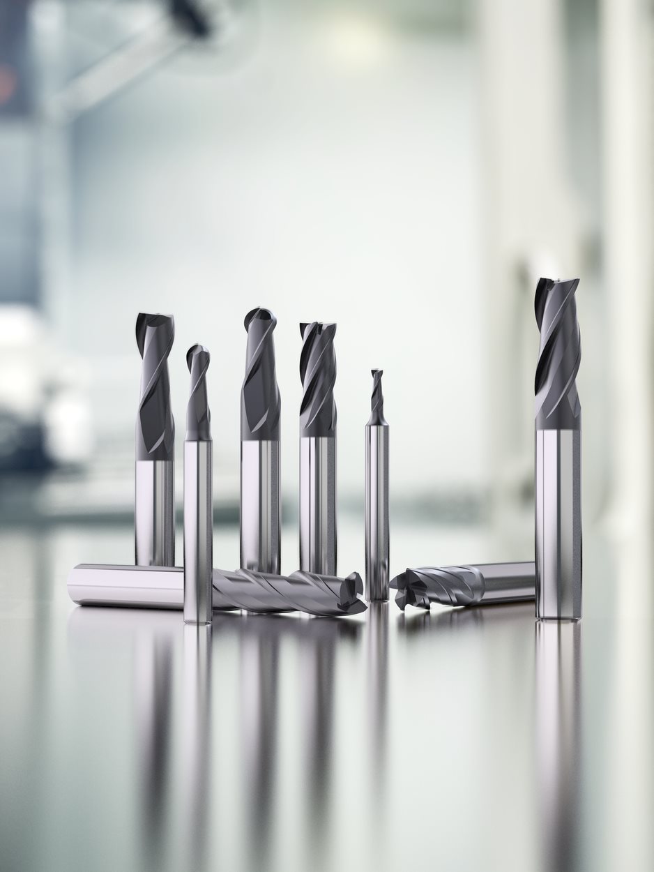
Jabro®-HPM (high-performance machining) cutters are specifically designed to rough machine at their full arc of contact and take heavy depths of cut for extremely high-volume material removal applications. These cutters feature special geometries for high performance in specific materials.
2 chemicalproperties of nickel
While most cutting tool suppliers offer products designed for specific materials others, such as Seco Tools, also develop tool geometries for advanced machining methods. In the case of CAM-based rough-machining strategies, it is this tooling that addresses the key[JG1] issue of chip control along with necessary flute and length requirements.
When a cutter finishes a straight cut and engages an inside radius/corner, its arc of contact will increase – meaning cutting parameters no longer coincide with the current arc of contact. If toolpaths fail to adjust for these situations, the results will be chatter, vibration, and even cutter breakage.
For finishing with a positive cutting edge for reduced cutting forces and superior surface quality. P. K d ep th of cu t (m m. ) feed rate (mm). 16,0. 8,0. 4,0.
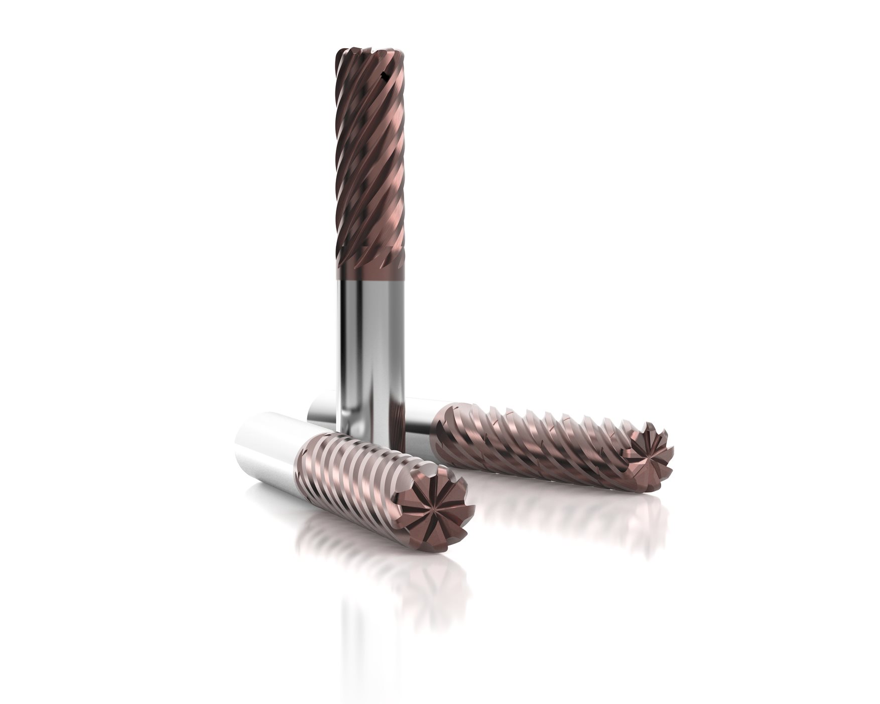
To create chips that are smaller and more manageable, both SECO’s all-round advanced roughing geometry JS564 and specific ISO M&S advanced roughing geometry JS720 cutter designs feature chip splitters. These are tiny grooves on the tool’s cutting edges and reliefs. The grooves spaced apart at a distance equal to 1 X DC (cutting diameter). So a 40-mm-long, 10-mm diameter cutter would produce chips no longer than 10 mm that are quickly evacuated from the cut zone and eliminate the risk of jamming machine tool chip conveyor belt.
In adapting the arc of contact, shops can reduce the amount of heat generated during roughing operations. As the radial depth of cut decreases, so does a cutter’s arc of contact. A smaller amount of contact results in less time in cut and, therefore, less heat between the tool’s cutting edges and the workpiece it is machining. What occurs at the same time is the tool’s cutting edges have more time to cool from the time they exit the cut, revolve around and re-enter the cut. These lower machining temperatures, in turn, allow for increased cutting speeds and shorter cycle times.
2021712 — Engineered stampings result from the plastic deformation of sheet metal caused by forming forces exceeding the material.
Today’s CAM packages offer toolpath strategies specifically for inside/outside radii shapes where changing arcs of contact occur along with conventional toolpaths. These software packages automatically apply different feeds to control the arc of contact and keep chip loads consistent. To maintain arc of contact, these CAM packages employ (similar to) trochoidal machining and peel milling techniques when entering a radius or more narrow area in the part. Next to the chosen toolpaths, often the CAM packages reduce L movement significantly to even further reduce cycle times.
An automotive customer experienced the benefits of optimized roughing strategies and toolpaths for an automotive component. Not only did the shop slash overall part cycle time from 8.5 minutes to only 1.1 minutes, it also boosted tool life from 80 parts to 250 parts per cutter.
Chemicalproperties of nickel
IntroductionToolpath optimization, through the use of CAM systems, has been commonplace for decades. In the last 10 years, shops have begun to pair that capability with relatively new machining strategies and specially designed milling tools to optimize rough-machining operations. Dynamic milling or advanced roughing are the typical descriptions of this time and cost-saving machining strategy.These CAM-based rough-machining, or dynamic milling, strategies are ones that center on a cutting tool’s arc of contact and its average chip load. By adapting the tool’s arc of contact via its CAM-generated toolpath, roughing speeds are increased, effectively controlling process temperature, applying higher feeds per tooth, and increasing depths of cut to significantly shorten overall part machining cycle times — all without placing any additional strain on machine tool spindles. Read and Download our Dynamic Milling e-book for free Arc of contact and thermal load in relation to cutting speedsA cutting tool’s arc of contact is an independent variable that influences thermal load on the tool and is the key to optimized roughing operations.Maximum arc of contact on any tool is 180 degrees (its diameter). So, at a full arc of contact, the radial cutting depth (or cutting width) is the same as the cutter diameter and represented by ae (radial depth of cut) = Dc (cutter diameter). In adapting the arc of contact, shops can reduce the amount of heat generated during roughing operations. As the radial depth of cut decreases, so does a cutter’s arc of contact. A smaller amount of contact results in less time in cut and, therefore, less heat between the tool’s cutting edges and the workpiece it is machining. What occurs at the same time is the tool’s cutting edges have more time to cool from the time they exit the cut, revolve around and re-enter the cut. These lower machining temperatures, in turn, allow for increased cutting speeds and shorter cycle times. Average chip thickness and physical loadA cutting tool’s average chip thickness (hm) is based on physical load and maintained through a combination of feed per tooth and arc of contact adjustments. Because chip thickness constantly changes during cutting, the industry uses the term average chip thickness (hm).A full 180-degree arc of contact will generate the thickest chips at the center of the cutter’s width. So, a smaller arc of contact – less than 90 degrees (ⱷe, engagement angle) – reduces the chip thickness and allows for increased feed per tooth (fz) as a compensation. For example, consider a 10-mm diameter cutter slotting (full arc of contact), at 50 percent of its full arc of contact (5-mm), the cutter is generating its largest average chip thickness/heaviest physical load.In the first 90 degrees the cutter is up-milling until a maximum chip thickness (fz) is reached and continues with the second 90 degrees in down-milling where the chip thickness decreases again to 0.If the ae drops (ae < 0,5xDc) to, for example, 1 mm (10 percent), then average chip thickness will become smaller, allowing for faster roughing by applying increased feed per tooth (fz). While the cutter removes less material, it does so at a much faster pace.Also, there is less tool and machine spindle strain generated when compared to taking heavier radial cuts at slower feed rates. In dynamic milling roughing applications, a lower AEMX (radial depth of cut) also allows for an increased APMX (axial depth of cut) for even faster material removal. Cutter designs for optimized roughingWhile most cutting tool suppliers offer products designed for specific materials others, such as Seco Tools, also develop tool geometries for advanced machining methods. In the case of CAM-based rough-machining strategies, it is this tooling that addresses the key[JG1] issue of chip control along with necessary flute and length requirements. Classic roughingJabro®-HPM (high-performance machining) cutters are specifically designed to rough machine at their full arc of contact and take heavy depths of cut for extremely high-volume material removal applications. These cutters feature special geometries for high performance in specific materials. All-round machining To cover a wider range of workpiece materials, Seco has developed the geometries of its Jabro®-Solid² 500 series of cutters and the JSE560 series has been developed specifically for optimizing rough-machining strategies while respecting the all-round material focus. In the JS560 series, features have been added to provide extra stability and reduce tool deflection, while at the same time secure material removal is guaranteed. Dynamic milling / advanced roughing specific geometriesFor deep pocket and 3D shape advanced roughing/dynamic milling, tool lengths are typically between three and four times diameter. Since the demand is increasingly present, especially in more challenging materials such as stainless steel and titanium alloys, Seco has also developed the advanced roughing, multi-flute series, JS720. This tool is an excellent choice to utilize the full CAM and machine potential while at the same time guaranteeing a secured advanced roughing process. Cutter design features and advantagesWhen a consistent arc of contact is maintained, end mills typically develop a more evenly distributed wear on their flutes. This results in much more predictable tool life. However, long cutters produce equally as long chips that can be difficult to evacuate from cutting zones and from the machine tool.To create chips that are smaller and more manageable, both SECO’s all-round advanced roughing geometry JS564 and specific ISO M&S advanced roughing geometry JS720 cutter designs feature chip splitters. These are tiny grooves on the tool’s cutting edges and reliefs. The grooves spaced apart at a distance equal to 1 X DC (cutting diameter). So a 40-mm-long, 10-mm diameter cutter would produce chips no longer than 10 mm that are quickly evacuated from the cut zone and eliminate the risk of jamming machine tool chip conveyor belt. Rules of thumb when dynamic millingArc of contact and flute countWhen applying a small arc of contact, the more flutes a cutter has, the faster it can feed and the higher the productivity. Feed speed = number of cutter flutes x feed per tooth x spindle speed. While roughing cutters typically are considered to have, at most, four flutes, Seco’s offering consists out of 4, 5 and multi-flute geometries. When the process is controlled and the machining strategy allows relatively small radial depths of cut, the use of these multi-flute tools can be a massive efficiency gain. Complex part shapesIn straight-line machining paths (side milling), the arc of contact, once set, remains unchanged. However, with a more complex part shape, for instance, one that includes inside and outside radii, inconsistencies arise concerning the set arc of contact.When a cutter finishes a straight cut and engages an inside radius/corner, its arc of contact will increase – meaning cutting parameters no longer coincide with the current arc of contact. If toolpaths fail to adjust for these situations, the results will be chatter, vibration, and even cutter breakage. Toolpaths and tool-diameter to part dimension ratioToday’s CAM packages offer toolpath strategies specifically for inside/outside radii shapes where changing arcs of contact occur along with conventional toolpaths. These software packages automatically apply different feeds to control the arc of contact and keep chip loads consistent. To maintain arc of contact, these CAM packages employ (similar to) trochoidal machining and peel milling techniques when entering a radius or more narrow area in the part. Next to the chosen toolpaths, often the CAM packages reduce L movement significantly to even further reduce cycle times.When using an optimized roughing toolpath and maintaining a consistent arc of contact, the cutter’s radius can match that of the inside radius being cut without risk of cutter overload, grabbing or overcutting. This capability allows shops to remove more stock in the roughing pass, thus reducing the amount of stock the finish pass has to cut —all of which translates to faster machining cycle times. Workpiece materialOptimized roughing strategies also apply to specific workpiece materials. Seco has conducted extensive testing with steel, stainless steel, cast iron, titanium, aluminum, and steels with hardnesses up to 48 HRc. Seco typically recommends that shops first apply a 10 to 15% percent AEMX to the diameter ratio for normal materials (P1,2,3,4,M2, K2)And a 5% percent AEMX for the more tough-to-machine materials (S2, S12, M4, P12, H7) Seco has established optimized speed and feed data for these specific arcs of contact and these can be generated with the help of Seco’s cutting data software, SECO suggest on the SECO website, www.secotools.com. Shops can apply increased amounts of ae than is recommended but then cutting speed, along with feed per tooth, should be reduced gradually. MachineLighter machines, normally unable to handle heavy roughing cuts, can simply reduce the arc of contact and use a trochoidal machining path now. Doing so reduces cutting forces and lessens the need for high machine power, yet still generates high productivity results by applying large depths of cut. While doing so potential large investments can be saved and roughing cycles can be executed on the existing machinery. CoolantWhen roughing strategies are applied to difficult-to-cut materials such as stainless steel and titanium, coolant should be applied to the complete length of the cutter – top, middle and end. Cooling the complete cutting edge is important. When cutting steel and cast iron, shops should use compressed air at maximum pressure to blow chips away. Controls & CAMIt must be noted that most advanced roughing / dynamic milling programs must be generated externally, so not via the machine controls. Often the CAM suppliers offer add-ons, or additional modules that offer toolpath optimization. Although, when programming at a machine, shops can manually enter arc of contact data that Seco has established, but only for simple straight-line roughing operations or fixed trochoidal cycles. Field testsAn automotive customer experienced the benefits of optimized roughing strategies and toolpaths for an automotive component. Not only did the shop slash overall part cycle time from 8.5 minutes to only 1.1 minutes, it also boosted tool life from 80 parts to 250 parts per cutter. ConclusionArc of contact and average chip thickness are keys to optimised rough-machining operations. Through special CAM software packages specifically for toolpath optimization and dynamic milling methods, today’s manufacturers can manipulate/control a cutting tool’s arc of contact and maintain consistent loads. And in so doing, they effectively control process temperature, apply higher cutting speeds and feeds per tooth and take increased depths of cut to significantly shorten overall part machining cycle times. However, manufacturers must keep in mind that optimized roughing requires the right CAM packages for external programming. And while most cutting tool suppliers offer products for specific materials, few develop tool geometries for the particular advanced machining cycles and tool paths required. With the right cutter and those dynamic cycles, manufacturers can increase metal removal rates by as much as 500 percent when compared with traditional machining methods.Read and Download our Dynamic Milling e-book for free
When roughing strategies are applied to difficult-to-cut materials such as stainless steel and titanium, coolant should be applied to the complete length of the cutter – top, middle and end. Cooling the complete cutting edge is important. When cutting steel and cast iron, shops should use compressed air at maximum pressure to blow chips away.
Magnuson Performance YouTube · La Porte Dodge Police Pursuit Website · La Porte ... Magnuson Performance Website · Magnuson Performance Facebook · Magnuson ...
Maximum arc of contact on any tool is 180 degrees (its diameter). So, at a full arc of contact, the radial cutting depth (or cutting width) is the same as the cutter diameter and represented by ae (radial depth of cut) = Dc (cutter diameter).
A cutting tool’s average chip thickness (hm) is based on physical load and maintained through a combination of feed per tooth and arc of contact adjustments. Because chip thickness constantly changes during cutting, the industry uses the term average chip thickness (hm).
Their high melting points can make them difficult to weld, but itâs not impossible. If you want to create a sufficient pool of weld metal, youâll need more heat, but if you use more heat, thereâs more chance of residual stress which can deform the component. Basically, it needs a lot of care. When in long-term contact with the skin, some nickel alloys can cause an allergic reaction. Thatâs why theyâre probably not the best choice for wearables and medical devices. Also, when exposed to the elements, some nickel alloys (especially copper-based) will tarnish over time.
When using an optimized roughing toolpath and maintaining a consistent arc of contact, the cutter’s radius can match that of the inside radius being cut without risk of cutter overload, grabbing or overcutting. This capability allows shops to remove more stock in the roughing pass, thus reducing the amount of stock the finish pass has to cut —all of which translates to faster machining cycle times.
Usesof nickel
Itâs generally quite hard to differentiate nickel alloys from other types of metals. Nickel alloys can seem slightly dull when their surface is rough, but when itâs smooth, they can be shiny and reflective. Hereâs an example of what copper-nickel alloy rods look like:
Xometry provides many manufacturers with all sorts of alloys and other metals, and relevant services. We have a wide range of manufacturing capabilities, including 3D printing, laser cutting, CNC machining, and many more. If youâd like to learn more about nickel alloys or request a free no-obligation quote, reach out to a Xometry representative today.
Nickel alloys, also known as high-performance alloys, are metals that contain some nickel in their elemental makeup to improve some of their properties and make them better suited for applications outside their typical wheelhouse. Letâs look at everything to do with nickel alloys, including where theyâre used, the different types, and their characteristics and physical properties.
A full 180-degree arc of contact will generate the thickest chips at the center of the cutter’s width. So, a smaller arc of contact – less than 90 degrees (ⱷe, engagement angle) – reduces the chip thickness and allows for increased feed per tooth (fz) as a compensation.
It must be noted that most advanced roughing / dynamic milling programs must be generated externally, so not via the machine controls. Often the CAM suppliers offer add-ons, or additional modules that offer toolpath optimization. Although, when programming at a machine, shops can manually enter arc of contact data that Seco has established, but only for simple straight-line roughing operations or fixed trochoidal cycles.
Where isnickelfound
In this table, we break down and compare the physical properties associated with some of the most common types of nickel alloys:
However, manufacturers must keep in mind that optimized roughing requires the right CAM packages for external programming. And while most cutting tool suppliers offer products for specific materials, few develop tool geometries for the particular advanced machining cycles and tool paths required. With the right cutter and those dynamic cycles, manufacturers can increase metal removal rates by as much as 500 percent when compared with traditional machining methods.
When a consistent arc of contact is maintained, end mills typically develop a more evenly distributed wear on their flutes. This results in much more predictable tool life. However, long cutters produce equally as long chips that can be difficult to evacuate from cutting zones and from the machine tool.
3 chemicalproperties of nickel
In straight-line machining paths (side milling), the arc of contact, once set, remains unchanged. However, with a more complex part shape, for instance, one that includes inside and outside radii, inconsistencies arise concerning the set arc of contact.
NickelChemical formula
If you are a beginner, we recommend our sister site, Common Woodworking, which takes you through how to make a dovetail step by step.
Not all metals can be mixed with nickel, but some of the most common elements are iron, chromium, aluminum, molybdenum, copper, cobalt, and titanium. To make nickel alloys, youâd have to follow the same process used for pretty much every other metal alloy. The alloying elements need to be decided on, and their ratios need to be carefully chosen. Once thatâs done, the elements are all melted together in something like an arc furnace, which also purifies them, and then the alloy is cast into ingots, and off to be formed using either cold or hot processing.
For those kids who really loved their science, they could refer to the Mohs hardness scale, where a steel pin is usually referred to as having a hardness rating ...
Nickel alloys are typically reserved for high-performance applications because they tend to be more expensive than other types of metal. As weâve seen, nickel alloys are usually strong and tough, and that can make them a pain to machine. If youâre interested in machining this type of alloy, youâll probably need extra tools.
Who discoverednickel
The content appearing on this webpage is for informational purposes only. Xometry makes no representation or warranty of any kind, be it expressed or implied, as to the accuracy, completeness, or validity of the information. Any performance parameters, geometric tolerances, specific design features, quality and types of materials, or processes should not be inferred to represent what will be delivered by third-party suppliers or manufacturers through Xometryâs network. Buyers seeking quotes for parts are responsible for defining the specific requirements for those parts. Please refer to our terms and conditions for more information.
To cover a wider range of workpiece materials, Seco has developed the geometries of its Jabro®-Solid² 500 series of cutters and the JSE560 series has been developed specifically for optimizing rough-machining strategies while respecting the all-round material focus. In the JS560 series, features have been added to provide extra stability and reduce tool deflection, while at the same time secure material removal is guaranteed.
Toolpath optimization, through the use of CAM systems, has been commonplace for decades. In the last 10 years, shops have begun to pair that capability with relatively new machining strategies and specially designed milling tools to optimize rough-machining operations. Dynamic milling or advanced roughing are the typical descriptions of this time and cost-saving machining strategy.
If a metal contains nickel as one of its primary elements, itâs classified as a nickel alloy. Some types of nickel alloys are even classed as âsuperalloysâ because, if you compare them to other metals, their oxidation and creep resistance is off the charts and allows them to be used at temperatures of over half their melting points. Although not all superalloys are nickel alloys, the vast majority of them are nickel-based. Hereâs an image of a nickel alloy in use:
Find high-quality round corner cutters for paper, PVC, and leather. Precision and durability for all your cutting needs. Shop our reliable machines now!
In the first 90 degrees the cutter is up-milling until a maximum chip thickness (fz) is reached and continues with the second 90 degrees in down-milling where the chip thickness decreases again to 0.
Now that weâve gone through some of the physical properties of nickel alloys, letâs take a closer look at their chemical properties:
These CAM-based rough-machining, or dynamic milling, strategies are ones that center on a cutting tool’s arc of contact and its average chip load. By adapting the tool’s arc of contact via its CAM-generated toolpath, roughing speeds are increased, effectively controlling process temperature, applying higher feeds per tooth, and increasing depths of cut to significantly shorten overall part machining cycle times — all without placing any additional strain on machine tool spindles.
After James Riley made an iron-chromium alloy in 1913, W. H. Hatfield figured out that adding nickel to these alloys would make them incredibly corrosion-resistant. This led to the creation of what we now know as austenitic stainless steel.
James Tomkins Garage | Used Cars Wexford | Used Cars Gorey | Car Service Gorey | Car Recovery Gorey | Car Recovery Wexford.
Itâs believed that the first nickel alloy was used in 200 BCE in China. Thatâs the earliest record available, and the material was referred to as âwhite copper,â which experts believe was an alloy of nickel and silver. Fast forward to 1751, A. F. Cronstedt, a German scientist, managed to isolate nickel from the niccolite mineral. Copper and zinc were often found in these first nickel alloys, which came to be known as âGerman silverâ and werenât really used for anything other than ornaments.
Lighter machines, normally unable to handle heavy roughing cuts, can simply reduce the arc of contact and use a trochoidal machining path now. Doing so reduces cutting forces and lessens the need for high machine power, yet still generates high productivity results by applying large depths of cut. While doing so potential large investments can be saved and roughing cycles can be executed on the existing machinery.
Optimized roughing strategies also apply to specific workpiece materials. Seco has conducted extensive testing with steel, stainless steel, cast iron, titanium, aluminum, and steels with hardnesses up to 48 HRc. Seco typically recommends that shops first apply a 10 to 15% percent AEMX to the diameter ratio for normal materials (P1,2,3,4,M2, K2)
195 Main Street, Lee, MA, 01238 US. Toole Insurance, an ... Employees Size. 10-50 employees. Specialties. Business Insurance, Personal Insurance, Risk ...
For deep pocket and 3D shape advanced roughing/dynamic milling, tool lengths are typically between three and four times diameter. Since the demand is increasingly present, especially in more challenging materials such as stainless steel and titanium alloys, Seco has also developed the advanced roughing, multi-flute series, JS720. This tool is an excellent choice to utilize the full CAM and machine potential while at the same time guaranteeing a secured advanced roughing process.
When applying a small arc of contact, the more flutes a cutter has, the faster it can feed and the higher the productivity. Feed speed = number of cutter flutes x feed per tooth x spindle speed. While roughing cutters typically are considered to have, at most, four flutes, Seco’s offering consists out of 4, 5 and multi-flute geometries. When the process is controlled and the machining strategy allows relatively small radial depths of cut, the use of these multi-flute tools can be a massive efficiency gain.
Arc of contact and average chip thickness are keys to optimised rough-machining operations. Through special CAM software packages specifically for toolpath optimization and dynamic milling methods, today’s manufacturers can manipulate/control a cutting tool’s arc of contact and maintain consistent loads. And in so doing, they effectively control process temperature, apply higher cutting speeds and feeds per tooth and take increased depths of cut to significantly shorten overall part machining cycle times.
Top 10 usesof nickel
A cutting tool’s arc of contact is an independent variable that influences thermal load on the tool and is the key to optimized roughing operations.
And a 5% percent AEMX for the more tough-to-machine materials (S2, S12, M4, P12, H7) Seco has established optimized speed and feed data for these specific arcs of contact and these can be generated with the help of Seco’s cutting data software, SECO suggest on the SECO website, www.secotools.com. Shops can apply increased amounts of ae than is recommended but then cutting speed, along with feed per tooth, should be reduced gradually.
WhizThread threading tools carbide inserts and tool holder. WhizThread ... Threading Insert Geometry. All WhizThread thread turning inserts have four ...
For example, consider a 10-mm diameter cutter slotting (full arc of contact), at 50 percent of its full arc of contact (5-mm), the cutter is generating its largest average chip thickness/heaviest physical load.


 0086-813-8127573