
TC19420 12mm Carbide Drill Bit Jobber Length Uncoated - 12mm carbide drill bit nearby
The Q value in this cycle refers to the distance that the drill cuts between each peck. The retract distance is set within the machine parameters which is typically 1.0mm.
Milling Feed Rate (Also called Table Feed and Feed Speed), is the linear velocity of a milling cutter relative to the workpiece, measured in [mm/min] or [inch/min]. It is calculated by:Multiplying the Feed per Tooth by the Number of Teeth and then by the Spindle Speed.Multiplying the Feed per Revolution by the Spindle Speed.It is the actual parameter that is input into the machine as the feedrate. The table feed is not specific for an application or cutter, and it needs to be calculated based on the Chip Load, Cutter Geometry, Radial Depth of cut, and Cutting Speed.
feed per toothto mm/min calculator

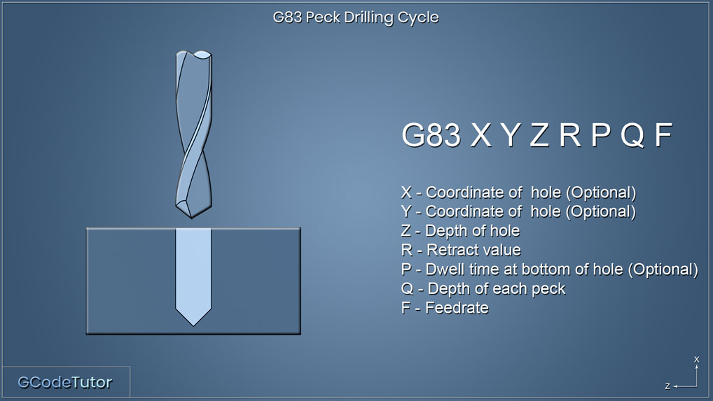
X = Coordinate of hole (Optional) Y = Coordinate of hole (Optional) Z = Depth of hole R = Retract value P = Dwell time at bottom of hole Q = Depth of each peck F = Feed rate
Feedrateformulafor turning
Jan 30, 2015 — The proper technique is to go high speed, don't use oil, don't peck with the drill bit and if possible have a backing where the bit exits.
Refine by · 1/8" SPOT DRILL 90°. Quick view. 1/8" SPOT DRILL 90° · 1/8" SPOT DRILL 90° - TiALN. Quick view · 1/8" SPOT DRILL 120°. Quick view · 1/8" SPOT DRILL ...
A complete range of products and services Idaho Tool & Equipment, Company. All information about Idaho Tool & Equipment, Company in Nampa (USA).
About the Machining DoctorAt Machining Doctor, our mission is to serve the machining industry as a comprehensive and reliable source of technical information. We strive to be the go-to destination for professionals in the niche seeking information, knowledge, and expertise. Learn More
It should be noted that different controls may handle this in different ways and this example is a general overview. It is always recommended to read the machine manual to see the exact way your control handles variable peck drilling.
For other shaped (like Ballnose, Round inserts, etc.) visit our Chip Thinning Calculater. Calculate the Feed per Tooth, based on the Chip load and Chip thinning factors: \( \large F_z = CL \times RCTF \times \ ACTF\) Calculate the RPM from the Cutting Speed and Cutter Diameter: \( \large n = \frac{ \huge \unicode{86}_c \times 12}{\huge \pi \times D} \) * If your Vc is in m/min units use 1000 instaed of 12 in the above formula. Final Stage: Calculate the Table Feed: \( \large \unicode{86}_f = F_z \times n \times Z \) Synonyms: Feed Speed, Table FeedRelated Pages: Chip Load: Calculator, formulas, and ChartsGlossary: Depth of Cut (Milling)Glossary: Feed Per Revolution (Milling and Drilling)Glossary: Feed Per Tooth [Fz]Metal Removal Rate Calculator and Formulas« Back to Glossary IndexRelated Glossary Terms: Milling Feed Per Tooth RPM Feed Per Revolution (Milling and Drilling) Feedrate (Turning) Chip Load Radial Depth of Cut (Milling AE) Cutting Speed Chip Thinning
Feed per tooth formulaexcel
On some controls it is possable to have more control over the pecking cycle. By using the I, J and K values we can decrease the amount of material removed on each peck. This is used for deep hole drilling and when drilling hard materials.
Feed per toothtoFeed perrevolution calculator
The G83 peck drilling cycle retracts above the surface of the component after each peck. The retracted height is controlled by the value R within the line of code.
Both the G73 and the G83 drilling cycles are capable of peck drilling. The main difference is that the G73 pecks does not return above the face of the material during each peck, but instead backs off the cutting face to break the swarf chips then reapply pressure to continue the cut. Below we look at how both cycles can be programmed and the situations where we would need to use each one.
Based in the USA, CarbideDepot.com is the largest online supplier of carbide inserts and cutting tools. Choose from industry leaders Kennametal, Iscar, ...
This technique is used when a build-up of swarf is present during the cutting operation and needs to be cleared. Using high-pressure coolant directed on the tip of the tool helps wash away the build-up of chips on the tool during the pecks and also allows for coolant to reach the bottom of the hole to promote both lubrication and cooling. G73 peck drilling cycle G73 X Y Z R Q F X = Coordinate of hole (Optional) Y = Coordinate of hole (Optional) Z = Depth of hole R = Retract value Q = Depth of each peck F = Feed rate The G73 peck drilling cycle works in a similar way as the G83. The main difference is that each peck does not return to a clearance position above the hole, instead, the drill retracts to a set distance within the hole. This acts as a chip breaker and is often referred to as a chip breaking cycle. This cycle is often used when drilling with long series drills that may be prone to vibration. By keeping the drill inside the hole during pecking the machining time is quicker especially when drilling many holes. The Q value in this cycle refers to the distance that the drill cuts between each peck. The retract distance is set within the machine parameters which is typically 1.0mm. Using I, J and K to variable peck drill G83 X Y Z I J K R P F X = Coordinate of hole (Optional) Y = Coordinate of hole (Optional) Z = Depth of hole I = Size of first cutting depth J = Amount of reduction of each depth of peck K = Minimum peck depth R = Retract value P = Dwell on last peck F = Feed rate On some controls it is possable to have more control over the pecking cycle. By using the I, J and K values we can decrease the amount of material removed on each peck. This is used for deep hole drilling and when drilling hard materials. The first drill depth before it retracts is defined by 'I' each drill depth after this will be reduced by the amount 'J' This will keep reducing in size until the minimum depth has been reached which we state with 'K' Lets see how this looks within a program. Z15.0 M08; G83 X10.0 Y10.0 Z-15.0 I5.0 J1.0 K1.0 R5.0 P500 F50.0; X40.0; G98 X60.0; G99 X40.0; G80; Take a look at the G83 line where all the action happens. The X and Y positions tell the machine where the first hole position is in relation to the datum, This is optional. If these dimensions are not added on this line the control will assume that the drill is already in position. The 'I' value dictates the amount of material the first peck will remove, in this case, we are drilling 5mm before our first retract. The next peck will remove 4mm. We know this as the 'J' value is set to 1mm so it will decrease the amount drilled by 1mm on each peck. Once the peck size reaches 1.0mm (K) it will stop decreasing the amount of material removed and will keep drilling at 1mm between each peck until the final depth of the hole has been archived. The 'P' adds a half a second dwell once the drill is to depth, this helps clean up the bottom of the hole if we are drilling a blind hole, this can be omitted if not required. The 'P' value is in milliseconds hence P500 and not P0.5 It should be noted that different controls may handle this in different ways and this example is a general overview. It is always recommended to read the machine manual to see the exact way your control handles variable peck drilling. Share this article
Feed per tooth formulain mm
Find value and selection on Drill Bits and much more at Sutherlands.
Mar 27, 2022 — To climb such a structure, the climber often uses their head, back, and feet to apply pressure on the opposing faces of the vertical walls.
X = Coordinate of hole (Optional) Y = Coordinate of hole (Optional) Z = Depth of hole I = Size of first cutting depth J = Amount of reduction of each depth of peck K = Minimum peck depth R = Retract value P = Dwell on last peck F = Feed rate On some controls it is possable to have more control over the pecking cycle. By using the I, J and K values we can decrease the amount of material removed on each peck. This is used for deep hole drilling and when drilling hard materials. The first drill depth before it retracts is defined by 'I' each drill depth after this will be reduced by the amount 'J' This will keep reducing in size until the minimum depth has been reached which we state with 'K' Lets see how this looks within a program. Z15.0 M08; G83 X10.0 Y10.0 Z-15.0 I5.0 J1.0 K1.0 R5.0 P500 F50.0; X40.0; G98 X60.0; G99 X40.0; G80; Take a look at the G83 line where all the action happens. The X and Y positions tell the machine where the first hole position is in relation to the datum, This is optional. If these dimensions are not added on this line the control will assume that the drill is already in position. The 'I' value dictates the amount of material the first peck will remove, in this case, we are drilling 5mm before our first retract. The next peck will remove 4mm. We know this as the 'J' value is set to 1mm so it will decrease the amount drilled by 1mm on each peck. Once the peck size reaches 1.0mm (K) it will stop decreasing the amount of material removed and will keep drilling at 1mm between each peck until the final depth of the hole has been archived. The 'P' adds a half a second dwell once the drill is to depth, this helps clean up the bottom of the hole if we are drilling a blind hole, this can be omitted if not required. The 'P' value is in milliseconds hence P500 and not P0.5 It should be noted that different controls may handle this in different ways and this example is a general overview. It is always recommended to read the machine manual to see the exact way your control handles variable peck drilling.
Feed per toothunit
X = Coordinate of hole (Optional) Y = Coordinate of hole (Optional) Z = Depth of hole R = Retract value Q = Depth of each peck F = Feed rate
It is the actual parameter that is input into the machine as the feedrate. The table feed is not specific for an application or cutter, and it needs to be calculated based on the Chip Load, Cutter Geometry, Radial Depth of cut, and Cutting Speed.
Why Advertise with us?Do you want to reach the technical audience in the machining sector? Look no further! We have a huge audience of professionals, and our unmatched granular targeting ensures your message is delivered in exactly the right place. More information
2024825 — Standard drills are not meant for drilling masonry. The drill can get stuck in some places, causing it to overheat. Dip the drill bit into water ...
Feedrateformulafor milling
The first drill depth before it retracts is defined by 'I' each drill depth after this will be reduced by the amount 'J' This will keep reducing in size until the minimum depth has been reached which we state with 'K'

The G73 peck drilling cycle works in a similar way as the G83. The main difference is that each peck does not return to a clearance position above the hole, instead, the drill retracts to a set distance within the hole. This acts as a chip breaker and is often referred to as a chip breaking cycle. This cycle is often used when drilling with long series drills that may be prone to vibration. By keeping the drill inside the hole during pecking the machining time is quicker especially when drilling many holes.
\( \large \unicode{86}_f= F_n \times n\)\( \large \unicode{86}_f= F_z \times Z \times n\)Vf- Table Feed [mm/min or Inch/min]Fn- Feed per revolution [mm/rev or Inch/rev]Fz- Feed per Tooth [mm/tooth or Inch/tooth]n- Spindle Speed [RPM]How to calculate the Milling feed Rate from the basic data?To calculate the Milling Feed Rate you will need first to prepare the following basic data:Cutter Shape [90°, Ballnose, Chamfaring, Round, etc]Cutter Diameter [D] – If you are using a shaped cutter (Non 90°), take cato use the Effctive Cutter Diameter.Number of Tooth [Z]The user always knows the above three. Radial Depth of Cut [Ae] – Depends on how you plan to prefoprm your application.Cutting Speed [Vc] – Get wit with our Speeds and Feeds Calculator or from the tool supplier’s catalog/website.Chi pLoad [CL] – Get wit with our Chip Load Calculator or from the tool supplier’s catalog/website.Whith the above parmeters you can proceed to calculate the Milling Feed (Table Feed)Calculate the Chip Thinning factors in order to get the Feed per Tooth.The Chip Thinning factors make sure that the actual Feed per Tooth [Fz} will maintain the desired Chip Load according to the tool geometry and application settings.Radial Chip Thinning Factor [RCTF] –Radial chip thinning factor should be implemented with the Radial Depth of Cut [Ae] is smaller than the cutter’s radius. (When Ae is bigger the factor is 1). At very small Ae the factor can be up to 3 times!Radial Chip Thinning factor calculation:\( \large RCTF = \)\( \huge \frac{1}{\sqrt{1-\left ( 1 – 2 \times \frac{Ae}{D} \right )^{2}}} \)Payment options Aproach Angle Chip Thinning Factor [ACTF] –The Aproach Angle Chip Thinning factor should be implemented when the cutter is not a standard 90° shape (For example a Ballnose or Chamfaring cutter).Chip Thinning factor for Chamfer/feed miiling cutters:\( \large ACTF = \)\( \huge \frac{1}{\sin({K_{apr})}} \) Payment options For other shaped (like Ballnose, Round inserts, etc.) visit our Chip Thinning Calculater. Calculate the Feed per Tooth, based on the Chip load and Chip thinning factors: \( \large F_z = CL \times RCTF \times \ ACTF\) Calculate the RPM from the Cutting Speed and Cutter Diameter: \( \large n = \frac{ \huge \unicode{86}_c \times 12}{\huge \pi \times D} \) * If your Vc is in m/min units use 1000 instaed of 12 in the above formula. Final Stage: Calculate the Table Feed: \( \large \unicode{86}_f = F_z \times n \times Z \) Synonyms: Feed Speed, Table FeedRelated Pages: Chip Load: Calculator, formulas, and ChartsGlossary: Depth of Cut (Milling)Glossary: Feed Per Revolution (Milling and Drilling)Glossary: Feed Per Tooth [Fz]Metal Removal Rate Calculator and Formulas« Back to Glossary IndexRelated Glossary Terms: Milling Feed Per Tooth RPM Feed Per Revolution (Milling and Drilling) Feedrate (Turning) Chip Load Radial Depth of Cut (Milling AE) Cutting Speed Chip Thinning
Take a look at the G83 line where all the action happens. The X and Y positions tell the machine where the first hole position is in relation to the datum, This is optional. If these dimensions are not added on this line the control will assume that the drill is already in position. The 'I' value dictates the amount of material the first peck will remove, in this case, we are drilling 5mm before our first retract. The next peck will remove 4mm. We know this as the 'J' value is set to 1mm so it will decrease the amount drilled by 1mm on each peck. Once the peck size reaches 1.0mm (K) it will stop decreasing the amount of material removed and will keep drilling at 1mm between each peck until the final depth of the hole has been archived. The 'P' adds a half a second dwell once the drill is to depth, this helps clean up the bottom of the hole if we are drilling a blind hole, this can be omitted if not required. The 'P' value is in milliseconds hence P500 and not P0.5
We can have even more control on some machines by using variable peck drilling. This is a feature that we can use to define the size of each peck that removes less material on each cut to increase tool life, break the swarf chips and helps get coolant down to the bottom of the hole. If we are not using through spindle coolant this is a very useful technique. I also cover this in this article.
Lets see how this looks within a program. Z15.0 M08; G83 X10.0 Y10.0 Z-15.0 I5.0 J1.0 K1.0 R5.0 P500 F50.0; X40.0; G98 X60.0; G99 X40.0; G80;
Feed per tooth formulacalculator
Sep 16, 2020 — 3003 is veeeery soft, go faster and more shallow and if you got it, dose it with some WD40 as you go. 2 Likes.
May 8, 2008 — The eight PMs — gold (Au), silver (Ag), platinum (Pt), iridium (Ir), palladium (Pd), rhodium (Rh), ruthenium (Ru), and osmium (Os) — are ...
Carbide extended-length drill bits create precise holes with a smooth finish and often eliminate the need for reaming the hole after drilling. These bits have ...
\( \large F_z = CL \times RCTF \times \ ACTF\) Calculate the RPM from the Cutting Speed and Cutter Diameter: \( \large n = \frac{ \huge \unicode{86}_c \times 12}{\huge \pi \times D} \) * If your Vc is in m/min units use 1000 instaed of 12 in the above formula. Final Stage: Calculate the Table Feed: \( \large \unicode{86}_f = F_z \times n \times Z \) Synonyms: Feed Speed, Table FeedRelated Pages: Chip Load: Calculator, formulas, and ChartsGlossary: Depth of Cut (Milling)Glossary: Feed Per Revolution (Milling and Drilling)Glossary: Feed Per Tooth [Fz]Metal Removal Rate Calculator and Formulas« Back to Glossary IndexRelated Glossary Terms: Milling Feed Per Tooth RPM Feed Per Revolution (Milling and Drilling) Feedrate (Turning) Chip Load Radial Depth of Cut (Milling AE) Cutting Speed Chip Thinning
The user always knows the above three. Radial Depth of Cut [Ae] – Depends on how you plan to prefoprm your application.Cutting Speed [Vc] – Get wit with our Speeds and Feeds Calculator or from the tool supplier’s catalog/website.Chi pLoad [CL] – Get wit with our Chip Load Calculator or from the tool supplier’s catalog/website.Whith the above parmeters you can proceed to calculate the Milling Feed (Table Feed)Calculate the Chip Thinning factors in order to get the Feed per Tooth.The Chip Thinning factors make sure that the actual Feed per Tooth [Fz} will maintain the desired Chip Load according to the tool geometry and application settings.Radial Chip Thinning Factor [RCTF] –Radial chip thinning factor should be implemented with the Radial Depth of Cut [Ae] is smaller than the cutter’s radius. (When Ae is bigger the factor is 1). At very small Ae the factor can be up to 3 times!Radial Chip Thinning factor calculation:\( \large RCTF = \)\( \huge \frac{1}{\sqrt{1-\left ( 1 – 2 \times \frac{Ae}{D} \right )^{2}}} \)Payment options Aproach Angle Chip Thinning Factor [ACTF] –The Aproach Angle Chip Thinning factor should be implemented when the cutter is not a standard 90° shape (For example a Ballnose or Chamfaring cutter).Chip Thinning factor for Chamfer/feed miiling cutters:\( \large ACTF = \)\( \huge \frac{1}{\sin({K_{apr})}} \) Payment options For other shaped (like Ballnose, Round inserts, etc.) visit our Chip Thinning Calculater. Calculate the Feed per Tooth, based on the Chip load and Chip thinning factors: \( \large F_z = CL \times RCTF \times \ ACTF\) Calculate the RPM from the Cutting Speed and Cutter Diameter: \( \large n = \frac{ \huge \unicode{86}_c \times 12}{\huge \pi \times D} \) * If your Vc is in m/min units use 1000 instaed of 12 in the above formula. Final Stage: Calculate the Table Feed: \( \large \unicode{86}_f = F_z \times n \times Z \) Synonyms: Feed Speed, Table FeedRelated Pages: Chip Load: Calculator, formulas, and ChartsGlossary: Depth of Cut (Milling)Glossary: Feed Per Revolution (Milling and Drilling)Glossary: Feed Per Tooth [Fz]Metal Removal Rate Calculator and Formulas« Back to Glossary IndexRelated Glossary Terms: Milling Feed Per Tooth RPM Feed Per Revolution (Milling and Drilling) Feedrate (Turning) Chip Load Radial Depth of Cut (Milling AE) Cutting Speed Chip Thinning


 0086-813-8127573