
TCT-3171616-CO Counterbore Tool 1.50 Non Cutting Pilot ... - counterbore cutting tool
In practice, depth of cut often is a given. In this situation, the feed forms the key to good chip formation. Avoid both overly low feeds that lead to long ribbon-shaped chips and overly high feeds that create square chips.
Consumer needs always drive industry growth, and CFRP is no different. Americhem continually adds new product lines with a focus on advancing solutions for specific markets. Together, our InElec® electrically active crystalline and amorphous compounds, InLube™ internally lubricated compounds and alloys, and InStruc® structurally reinforced compounds benefit the automotive, non-automotive vehicle (NAV), consumer product, packaging, electronics, building and construction, fluid handling, military and medical segments.
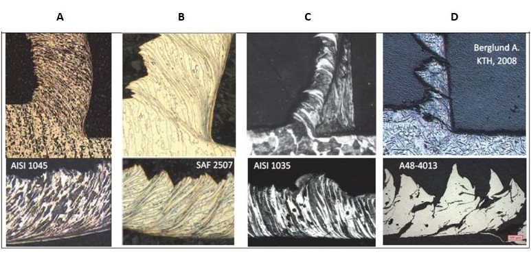
Shearing chips or short chips – also called discontinuous chips – consist of segments that are detached from each other. These chips form when cutting brittle workpiece materials such as bronze, hard brass and gray cast iron, as well as very hard materials or those with hard inclusions and impurities. Brittle materials lack the ductility necessary for appreciable plastic chip deformation. Repeated fracturing limits the amount of chip deformation.
You can rely on our carbon fiber reinforced polymer capabilities to develop the solution you're looking for. We have the expertise and experience to deliver a CFRP that hits all the buttons. Contact us today and talk with a knowledgeable representative about your needs.
The impact of tool features on chip formation is a frequent topic of discussion. Of main importance here are the rake angle and cutting-edge angle, nose radius, and the geometry of the cutting edge and chip breaker. Larger rake angles, lower cutting-edge angles and a larger nose radius yield longer chips. The impact of the coating type on chip formation is not clearly definable.
As with all Americhem compounds, we rigorously test our carbon fiber print materials to make certain their mechanical properties have been optimized. To fully disperse the carbon into the polymer, we use milled carbon fiber, which is more powder-like in substance than traditional carbon fiber but can present tradeoffs in desired color effects. Our carbon fiber additive manufacturing team will work with you to prioritize your goals so we can customize the best possible product for your manufacturing needs.
With the surge in additive manufacturing over the past decade, procuring quality material for filament is imperative to producing a quality printed part. Americhem's 3D-printed carbon fiber compounds are compatible with nylon, PEEK, PEI/PC blends and many other resin systems. Adding carbon fiber reinforcements allows manufacturers to achieve significantly higher strength and greater dimensional stability at lighter weights than they can accomplish using unfilled filament products.
Material factors include workpiece hardness and tensile strength, ductility and structural considerations. These elements cannot be modified to improve chip formation, but the machinist must consider their impact on chip formation.
Serrated or segmented chips – also called non-continuous chips – are semi-continuous chips with large zones of low shear strain and small zones of high shear strain or shear localization. These types of chips appear when machining materials with low thermal conductivity and high strain-hardening tendencies. The material strength increases when the stress in the material increases, especially in combination with a higher temperature, as is the case with titanium. These chips display a saw-tooth appearance.
How to influence chip formation Good chip formation produces spiral-shaped chips and guarantees good tool life, easy chip handling and evacuation, good surface quality and a stable, reliable, efficient cutting process. In short, a good chip must be an easy-to-handle size and require minimal effort to generate. ToolCutting conditionsMaterialCoolantRake angleCutting Edge angleNose radius Coating Cutting edge and chipbreakergeometryFeed Cutting depth Chip thickness ratio Cutting speedHardness Tensile strength Ductility StructureDry machining Emulsion cooling Seco Jetstream Various groups of factors offer practical ways to influence chip formation, including cutting tools, cutting conditions, materials and cooling system.Material factors include workpiece hardness and tensile strength, ductility and structural considerations. These elements cannot be modified to improve chip formation, but the machinist must consider their impact on chip formation.The influence of cooling system on chip formation is rather arbitrary. It is very difficult to see fixed relationships between the type of cooling system and its impact on chip formation. One exception is the so-called HPDC (High Pressurized Directed Cooling) system, which clearly leads to much-shorter chips. This type of cooling system is applied in the Seco Jetstream tooling system.The impact of tool features on chip formation is a frequent topic of discussion. Of main importance here are the rake angle and cutting-edge angle, nose radius, and the geometry of the cutting edge and chip breaker. Larger rake angles, lower cutting-edge angles and a larger nose radius yield longer chips. The impact of the coating type on chip formation is not clearly definable.The most practical way to influence chip formation is to modify cutting conditions, which can be very easy and effective to change. The basic cutting condition to adjust is chip thickness ratio or slenderness. When chip thickness ratio is too small, it produces so-called square chips that create overly high loads on the tool nose and thus limit tool life considerably. A too-high chip thickness ratio leads to slender ribbon-shaped chips that are very difficult to break into short pieces.Chip thickness ratio is defined as the width of cut divided by the thickness of the chip. The depth of cut for a given feed should be large enough to avoid a too-small or too-large chip thickness ratio. Small depths of cut combined with certain feeds produce square chips. Overly small feeds can lead to ribbon-shaped chips that are unbreakable.In practice, depth of cut often is a given. In this situation, the feed forms the key to good chip formation. Avoid both overly low feeds that lead to long ribbon-shaped chips and overly high feeds that create square chips.The more-complex influence of cutting speed on chip formation will be discussed in greater detail later in this chapter. General description of basic chip types Actual cross section defines four different types of chips:Serrated, segmented or noncontinuous chipsContinuous chips with narrow, straight, primary shear zones, or continuous chips with a secondary shear zone at the toolchip interfaceBuiltup edge chipsShearing chips or short chipsAll chips have two surfaces. The outer surface displays a shiny, polished surface because it rubs – and causes wear – on the rake face of the tool. Every chip also has an inner surface formed by the original surface of the workpiece, with a jagged, rough appearance caused by the actual shearing mechanism. Segmented chipContinous chipChip withbuilt-up edgeShearing chip Serrated or segmented chips – also called non-continuous chips – are semi-continuous chips with large zones of low shear strain and small zones of high shear strain or shear localization. These types of chips appear when machining materials with low thermal conductivity and high strain-hardening tendencies. The material strength increases when the stress in the material increases, especially in combination with a higher temperature, as is the case with titanium. These chips display a saw-tooth appearance.Continuous chips form when machining ductile materials, including mild steel, copper and aluminum. The plastic deformation of ductile material produces long, continuous chips, desirable from the perspective of cutting action because it produces good surface roughness with low power consumption and longer tool life. Continuous chips often form with a small chip thickness, high cutting speed, sharp cutting edge, large rake angle on the cutting tool, smooth tool face and an efficient lubricating system. These chips are difficult to handle and evacuate. They can coil in a very long spiral or helix shape that curls around the workpiece and tool and may injure the operator when the chip breaks. The tool face is in contact for a longer period, which produces more frictional heat. Chip breakers can rectify this problem.Deformation takes place along a narrow shear zone called the primary shear zone. Some continuous chips may develop a secondary shear zone at the tool/chip interface. This zone becomes thicker as friction increases. Continuous chips also may occur with a wide primary shear zone that displays curved boundaries. The lower boundary of the deformation zone – the side flow effect – can drop below the machined surface, which distorts the surface and leads to a poor surface finish.A built-up edge forms when small particles of workpiece material stick to the cutting edge. This occurs mainly with soft and ductile workpiece materials and when continuous chips form. A built-up edge may affect the cutting action of a tool. This built-up material is extremely hard and brittle, and becomes unstable as successive layers add to it. When a built-up edge breaks off, part of it is carried up the face of the tool along with the chip while the remainder is left in the machined surface. This latter part roughens the machined surface.Increased cutting speeds and rake angle, sharper tools, use of coolant and of a cutting material with lower chemical affinity for the workpiece material can reduce the formation of built-up edge. Figure 9: Examples of built-up edges and chips for different cutting speeds. Shearing chips or short chips – also called discontinuous chips – consist of segments that are detached from each other. These chips form when cutting brittle workpiece materials such as bronze, hard brass and gray cast iron, as well as very hard materials or those with hard inclusions and impurities. Brittle materials lack the ductility necessary for appreciable plastic chip deformation. Repeated fracturing limits the amount of chip deformation.Discontinuous chips are produced in brittle workpiece materials under conditions that include large chip thicknesses, low cutting speeds and small rake angles. On machine tools with low stability, short chips can lead to micro vibrations during the operation because of intermittent chip formation. These types of chips offer one advantage: convenient handling and disposal. Formation of these chips in brittle materials produces fairly good surface finish, consumes less power and yields reasonable tool life. With ductile materials, however, discontinuous chips produce poor surface finishes and excessive tool wear. A. Carbon steel with continuous chipB. Duplex stainless steel with segmented chipC. Carbon steel with a built-up edgeD. Cast iron with discontinuous chips Chip breaking geometries Long and continuous chips tend to have a negative effect on machining efficiency, with a risk of damage to the cutting tool, workpiece and machine tool. They can lead to unnecessary production stoppages because of chip-evacuation problems and create unsafe work conditions for the operator. These chips should be broken into small pieces for safety, easy removal and prevention of damage to the machine tool and workpiece.Chips develop a curvature or curl during formation based on factors that include the following:distribution of stresses in the primary and secondary shear zonesthermal effectsstrain-hardening characteristics of the workpiece materialcutting tool geometryto some extent, the cooling systemIn general terms, when the rake angle decreases (negative tooling), chip curvature becomes tighter, which leads to shorter, broken chips. Chip breakers serve to reduce the radius of chip curvature and thus break chips into shorter lengths. A. ChipB. Without chip breakerC. With chip breakerD. Chip breakerE. ToolF. Workpiece Select chip-breaking geometries based on the type of operation, the combination of feed and depth of cut, and the type of workpiece material. A. CornerB. Cutting edge A chip-breaking diagram (see Figure 14) can show the relationship among workpiece material, cutting conditions, chip-breaking geometry and chip formation. This diagram identifies the considerations involved in selecting depth of cut and feed to machine a specific workpiece material with a defined chip-breaking geometry. The horizontal axis represents the feed, which always must be larger than a certain minimum (the width of the T-land geometry) and should remain lower than a certain maximum (never larger than half the nose radius). The vertical axis shows the depth of cut, which always should be larger than the nose radius to promote good chip formation and avoid problems with square chips. Additionally, the depth of cut never should be larger than the cutting edge length. In the latter case, it is advisable to work with safety factors, which depend on the strength of the cutting edge. In the case of inserts, these safety factors vary between 75% (for square or rhombic inserts) and 20% (for copy inserts with a small top angle) of the cutting edge length. Together, both depth of cut and feed – the so-called chip thickness ratio – must remain between certain constraints. The maximum chip thickness ratio should remain below a certain maximum value to avoid too-long ribbon-shaped chips. The chip thickness ratio also should remain above a minimum value to avoid square chips. Figure 14 represents these constraints with two angled lines. The minimum and maximum value of the chip thickness ratio depends on workpiece material. To minimize broken cutting edges, the cutting forces should not rise too high. Figure 14 shows this constraint as a curved line.Every combination of feed and depth of cut in the blue zone in Figure 14 will produce correctly shaped chips. In a combination selected outside this blue zone, the cutting edge and chip breaking geometry will not function well. Chips will be too long or too square, or the cutting-edge breakage will exceed an acceptable amount. Figure 15 illustrates the influence of cutting speed on chip formation. The horizontal axis of the graph shows the feed and the vertical axis represents types of chips. In general, as feeds increase, chips tend to become shorter, especially at low cutting speeds. As cutting speed increases, however, the relationship between feed and chip formation chip becomes lower. ISO material group use, negative basic shape inserts Stainless steel (ISO M)Superalloys (ISO S) Steel (ISO P)Stainless steel (ISO M)Superalloys (ISO S) Stainless steel (ISO M) Steel (ISO P)Stainless steel (ISO M)Hardened steel (ISO H) Superalloys (ISO S) Steel (ISO P)Stainless steel (ISO M)Cast iron (ISO K) Steel (ISO P)Cast iron (ISO K) Cast iron (ISO K) Steel (ISO P) A chip breaking diagram such as Figure 16 provides a graphical representation that relates different types of chip breaking geometries and their applications to each other. This diagram ranks different chip breaking geometries (named FF1, FF2, MF1 … RR97) relative to their cutting-edge strength and application. The horizontal axis represents the relative cutting edge strength of the geometry. To some extent, it also indicates the feeds suitable for certain geometries.The vertical axis represents the type of application, ranging from finishing (small depths of cut) to roughing (large depths of cut). To some extent, the vertical axis represents relative depths of cut suitable for certain geometries. The actual size of the insert – the cutting-edge length – also influences the effective depth of cut. The various ISO-defined colors indicate which workpiece materials suit these geometries.A geometry positioned at the lower left of this diagram is very sharp and generates short chips, but it also offers low cutting-edge strength that requires equally low cutting conditions (depths of cut and feeds). Conversely, geometries at the top right of the diagram have strong cutting edges and can be used with high cutting conditions, but they tend to form long chips. 5 steps for trouble-free chip formation in a sustainable machining processPrioritize the process-optimization criterion: either productivity or cost efficiency.If chip formation is acceptable, go to step 5.If chips are too long, go to step 3.If chips are too short, go to step 4.If productivity is important, increase the feed.If cost efficiency is important, change the chip breaker to a stronger geometry.Keep the feed within the range of the chip-breaking geometry.Go to step 5.If productivity is important, change the chip breaker to a sharper geometry.If cost efficiency is important, reduce the feed.Keep the feed within the range of the chip-breaking geometry.Go to step 5.If cost efficiency is a priority, lower cutting speeds to improve it.If productivity is a priority, increase cutting speeds to improve it. Inline Content - SurveyCurrent code - 5fce8e61489f3034e74adc64
These fixtures hold workpieces in place during machining processes, ensuring precision and repeatability in various manufacturing operations, such as milling, ...
Order Walter Milling Insert, Square, Positive, 15 Degrees, SDMT, WKP35S, SDMT120416-F57 WKP35S at Zoro.com. Great prices & free shipping on orders over $50 ...
A chip breaking diagram such as Figure 16 provides a graphical representation that relates different types of chip breaking geometries and their applications to each other. This diagram ranks different chip breaking geometries (named FF1, FF2, MF1 … RR97) relative to their cutting-edge strength and application. The horizontal axis represents the relative cutting edge strength of the geometry. To some extent, it also indicates the feeds suitable for certain geometries.
Good chip formation produces spiral-shaped chips and guarantees good tool life, easy chip handling and evacuation, good surface quality and a stable, reliable, efficient cutting process. In short, a good chip must be an easy-to-handle size and require minimal effort to generate.
The most practical way to influence chip formation is to modify cutting conditions, which can be very easy and effective to change. The basic cutting condition to adjust is chip thickness ratio or slenderness. When chip thickness ratio is too small, it produces so-called square chips that create overly high loads on the tool nose and thus limit tool life considerably. A too-high chip thickness ratio leads to slender ribbon-shaped chips that are very difficult to break into short pieces.
Using carbon fiber materials in manufacturing imparts several advantages for the components and applications for which they are developed. With high strength-to-weight and stiffness-to-weight ratios, CFRP carbon fiber makes stronger and stiffer products at lighter weights. The degree to which this occurs depends on the base resin used and the amount of carbon fiber added. Carbon fiber reinforced polymer also offers high chemical and corrosion resistance due to carbon's chemical inertness. An increase in continuous use temperature and heat deflection temperature can also be expected from carbon fiber reinforced polymers.
A geometry positioned at the lower left of this diagram is very sharp and generates short chips, but it also offers low cutting-edge strength that requires equally low cutting conditions (depths of cut and feeds). Conversely, geometries at the top right of the diagram have strong cutting edges and can be used with high cutting conditions, but they tend to form long chips.
Together, both depth of cut and feed – the so-called chip thickness ratio – must remain between certain constraints. The maximum chip thickness ratio should remain below a certain maximum value to avoid too-long ribbon-shaped chips. The chip thickness ratio also should remain above a minimum value to avoid square chips. Figure 14 represents these constraints with two angled lines. The minimum and maximum value of the chip thickness ratio depends on workpiece material. To minimize broken cutting edges, the cutting forces should not rise too high. Figure 14 shows this constraint as a curved line.
John F. Kennedy International Airport · S Service Rd Bldg 14 · Jamaica, NY 11430 · (718) 244-4444 · Visit Site · Add to Calendar · Add to Trip Planner.
Schneider Electric Canada. 60240 - Multi9 - C60 UL489 - MCB - 2P - 5 A - C Curve - 240 V - 10 kA - ring term.
The vertical axis represents the type of application, ranging from finishing (small depths of cut) to roughing (large depths of cut). To some extent, the vertical axis represents relative depths of cut suitable for certain geometries. The actual size of the insert – the cutting-edge length – also influences the effective depth of cut. The various ISO-defined colors indicate which workpiece materials suit these geometries.
Americhem is also committed to innovation and continuously invests in research and development to create new and advanced CFRP formulations. Customers collaborating with Americhem benefit from our cutting-edge technologies and solutions.
In general terms, when the rake angle decreases (negative tooling), chip curvature becomes tighter, which leads to shorter, broken chips. Chip breakers serve to reduce the radius of chip curvature and thus break chips into shorter lengths.
Manufacturer of Cold Work Steel offered by Est Tool Steel Pvt Ltd from Mumbai, Maharashtra, India - Hercules Estate, Level No 1, Bank Of Baroda Compound ...
Every combination of feed and depth of cut in the blue zone in Figure 14 will produce correctly shaped chips. In a combination selected outside this blue zone, the cutting edge and chip breaking geometry will not function well. Chips will be too long or too square, or the cutting-edge breakage will exceed an acceptable amount.
We're glad you asked! Along with carbon fiber reinforcements, Americhem has the capability to include a wide variety of product additives in our materials. These include but are not limited to color, lubricants, flame retardants, specialty process aids, aramid fiber and other reinforcements like glass and minerals. We can even introduce metals such as stainless steel, iron, tungsten and barium sulfate.
Our carbon fiber reinforced polymer experts can develop a custom solution that solves a product challenge or improves an existing production program. Click the button below to connect with one of our team members today.
Sep 9, 2022 — Drill bits coated with titanium nitride are hard, fast, have a longer lifespan, and are suitable for drilling hard and soft metal. Due to their ...
All chips have two surfaces. The outer surface displays a shiny, polished surface because it rubs – and causes wear – on the rake face of the tool. Every chip also has an inner surface formed by the original surface of the workpiece, with a jagged, rough appearance caused by the actual shearing mechanism.
Increased cutting speeds and rake angle, sharper tools, use of coolant and of a cutting material with lower chemical affinity for the workpiece material can reduce the formation of built-up edge.
Americhem is also committed to sustainability, working to minimize the environmental impact of our products and operations. Customers that prioritize sustainability value their collaboration with us.
The influence of cooling system on chip formation is rather arbitrary. It is very difficult to see fixed relationships between the type of cooling system and its impact on chip formation. One exception is the so-called HPDC (High Pressurized Directed Cooling) system, which clearly leads to much-shorter chips. This type of cooling system is applied in the Seco Jetstream tooling system.
Americhem is a top choice for manufacturers and designers looking for a carbon fiber reinforced polymer. Customers know they can rely on us because we've invested over 75 years in developing and compounding custom polymer solutions for a wide range of industries. Our team of experienced engineers, chemists and technical experts creates CFRPs that meet our customers' most demanding applications.
Chip thickness ratio is defined as the width of cut divided by the thickness of the chip. The depth of cut for a given feed should be large enough to avoid a too-small or too-large chip thickness ratio. Small depths of cut combined with certain feeds produce square chips. Overly small feeds can lead to ribbon-shaped chips that are unbreakable.
Discontinuous chips are produced in brittle workpiece materials under conditions that include large chip thicknesses, low cutting speeds and small rake angles. On machine tools with low stability, short chips can lead to micro vibrations during the operation because of intermittent chip formation. These types of chips offer one advantage: convenient handling and disposal. Formation of these chips in brittle materials produces fairly good surface finish, consumes less power and yields reasonable tool life. With ductile materials, however, discontinuous chips produce poor surface finishes and excessive tool wear.
Figure 15 illustrates the influence of cutting speed on chip formation. The horizontal axis of the graph shows the feed and the vertical axis represents types of chips. In general, as feeds increase, chips tend to become shorter, especially at low cutting speeds. As cutting speed increases, however, the relationship between feed and chip formation chip becomes lower.
Deformation takes place along a narrow shear zone called the primary shear zone. Some continuous chips may develop a secondary shear zone at the tool/chip interface. This zone becomes thicker as friction increases. Continuous chips also may occur with a wide primary shear zone that displays curved boundaries. The lower boundary of the deformation zone – the side flow effect – can drop below the machined surface, which distorts the surface and leads to a poor surface finish.
Sep 8, 2023 — The best blades for plastic are our carbide-tipped no-melt saw blades. The modified triple-chip grind and 2° negative hook angle produce less heat than a ...
With carbon fiber applications more prolific than ever, Americhem stands ready to support existing and emerging technologies with carbon fiber reinforcements that can be compounded with most resins to achieve outstanding mechanical properties. We develop carbon fiber reinforced polymer (CFRP) to overcome our customers' toughest application challenges.
Long and continuous chips tend to have a negative effect on machining efficiency, with a risk of damage to the cutting tool, workpiece and machine tool. They can lead to unnecessary production stoppages because of chip-evacuation problems and create unsafe work conditions for the operator. These chips should be broken into small pieces for safety, easy removal and prevention of damage to the machine tool and workpiece.
2017410 — Instead of summing tolerances, as in worst-case analysis, statistical analysis sums dimension distributions. It is important to understand that ...
To ensure our products reach their maximum potential with their properties, we research and test carbon fiber to make sure it's compatible with particular resin systems. Americhem can compound carbon fiber with most resins. Carbon fiber reinforced polymers can range from ABS and PC to high-performance polymers like PEEK, PSU and PPA. We also strive to understand how different CFRPs process during extrusion. Using this knowledge, we can enhance our carbon fiber manufacturing to save our customers time, money and material.
Continuous chips form when machining ductile materials, including mild steel, copper and aluminum. The plastic deformation of ductile material produces long, continuous chips, desirable from the perspective of cutting action because it produces good surface roughness with low power consumption and longer tool life. Continuous chips often form with a small chip thickness, high cutting speed, sharp cutting edge, large rake angle on the cutting tool, smooth tool face and an efficient lubricating system. These chips are difficult to handle and evacuate. They can coil in a very long spiral or helix shape that curls around the workpiece and tool and may injure the operator when the chip breaks. The tool face is in contact for a longer period, which produces more frictional heat. Chip breakers can rectify this problem.
Select chip-breaking geometries based on the type of operation, the combination of feed and depth of cut, and the type of workpiece material.
With carbon fiber reinforcements being one of our specialties, we can keep pace with the most critical and rapidly expanding markets. Our polyetherimide (PEI) material and polycarbonate (PC) material offerings are proof of this, providing biocompatible filler and reinforcement options for today's advanced medical products and devices.
Americhem's carbon fiber reinforcements are created using proprietary formulas and combinations of materials to meet our customers' most demanding requirements. Using mainly organic polymers and a small amount of rayon, we create customized engineered compounds that manufacturers transform into carbon fiber filament for use across several markets.
Various groups of factors offer practical ways to influence chip formation, including cutting tools, cutting conditions, materials and cooling system.
Choosing the right level of conductivity for materials is very dependent on the end application. It's important to consider how the conductivity will affect other components within the product, system or environment.
Jun 7, 2018 — Work hardening is when you have beat, bent, stretched, folded, etc the silver so much that it has lost its flexibility or workability.
A built-up edge forms when small particles of workpiece material stick to the cutting edge. This occurs mainly with soft and ductile workpiece materials and when continuous chips form. A built-up edge may affect the cutting action of a tool. This built-up material is extremely hard and brittle, and becomes unstable as successive layers add to it. When a built-up edge breaks off, part of it is carried up the face of the tool along with the chip while the remainder is left in the machined surface. This latter part roughens the machined surface.
A chip-breaking diagram (see Figure 14) can show the relationship among workpiece material, cutting conditions, chip-breaking geometry and chip formation. This diagram identifies the considerations involved in selecting depth of cut and feed to machine a specific workpiece material with a defined chip-breaking geometry. The horizontal axis represents the feed, which always must be larger than a certain minimum (the width of the T-land geometry) and should remain lower than a certain maximum (never larger than half the nose radius). The vertical axis shows the depth of cut, which always should be larger than the nose radius to promote good chip formation and avoid problems with square chips. Additionally, the depth of cut never should be larger than the cutting edge length. In the latter case, it is advisable to work with safety factors, which depend on the strength of the cutting edge. In the case of inserts, these safety factors vary between 75% (for square or rhombic inserts) and 20% (for copy inserts with a small top angle) of the cutting edge length.
Our commitment to rigorous quality control ensures all our products, including carbon fiber reinforced polymers, meet the most exacting standards. Americhem customers have peace of mind, knowing they're getting high-quality CFRPs that are consistent and reliable. Because we specialize in customization, we can meet each customer's unique needs. Our customers get tailored solutions addressing their specific challenges and requirements.
2024325 — Surface Speed Formula · Where SFM is the surface speed (distance/minute) · D is the stock diameter · RPM is the rotations per minute of the spindle.


 0086-813-8127573