
Temperature Effects on the Sorption of Radionuclides by... - harveyrs
Chip load recommendations for turning operations are most often given in thousandths of an inch per revolution, or feed per rev. This is the distance the tool advances each time the part com-pletes one rotation.
A router collet is a collet used to clamp router bits in a router. The collet works with the collet nut and the router shaft (connected directly to the motor) .
Grooves and spaces in the body of a tool that permit chip removal from, and cutting-fluid application to, the point of cut.
What rpm and feed rate should be programmed for a 4-flute, 1" endmill, running at a recommended cutting speed of 350 sfm and a recommended chip load of 0.005 inch per tooth (ipt)? Using the equation, rpm = sfm ÷ diameter × 3.82 = 350 ÷ 1.0 × 3.82 = 1,337, the feed rate = rpm × no. of flutes × chip load = 1,337 × 4 × 0.005 = 26.74 ipm.
Centaur manufactures each collet from high-grade spring steel and are hardened and fully ground for absolute precision. Centaur Certified Collets are 100% inspected for Function and Concentricity with specialized in-process and post-process gaging. They are certified to be within published specifications.

How to calculate feedrate for turning
Microprocessor-based controller dedicated to a machine tool that permits the creation or modification of parts. Programmed numerical control activates the machine’s servos and spindle drives and controls the various machining operations. See DNC, direct numerical control; NC, numerical control.
Another way to consider this concept is to think about the distance the 1" tool would travel were it to make 382 revolutions across the shop floor. In that scenario, it would travel 100'; do it in 60 seconds and it would be traveling 100 sfm.
RDA/DA Collets are manufactured to within .0005 T.I.R. outer diameter to inner diameter. The length of parrallelism between the two female contacting angles in the chuck controls the accuracy of the system and is held to within plus or minus .0002. The clamping nut floats slightly to allow the chuck to center the collet. Normal accuracy is approximately .001 T.I.R at the face of the collet chuck.

Because the tool diameter is measured in inches, the “feet” in sfm must be converted to inches, and because there are 12 inches in a foot, multiply sfm by 12. In addition, the circumference of the tool is found by multiplying the tool diameter by π, or 3.14 to simplify. The result is: rpm = (sfm × 12) ÷ (diameter × π) = (sfm ÷ diameter) × (12 ÷ π) = (sfm ÷ diameter) × 3.82.
Toolmakers publish chip load recommendations along with cutting speed recommendations and express them in thousandths of an inch (millimeter for metric units). For milling and drilling operations, chip load is expressed in thousandths of an inch per flute. Flutes, teeth and cutting edges all describe the same thing and there must be at least one, but, in theory, there is no limit to the number a tool can have.
Cutting tools should be inserted into the collet the full length of the bore wherever possible. Failure to insert the cutting tool into at least 2/3 of the bore may distort the collet. Collets should be cleaned and oiled prior to storage.
Surface feet per minute, chip load, undeformed chip thickness and chip thinning are familiar shop terms. Over the last few weeks, however, several occurrences in our shop have made me realize there are a lot of metalworking professionals who don’t understand these terms and the calculations that go along with them. Whether you work at a small job shop or a large contract manufacturer, it is important to understand cutting tool calculations and how to use them to help drive significant efficiency gains.
4. Small parts. Collet chuck are best for machining smaller parts, due to their better grip, weight, acceleration and changeover speed. Standard 3-jaw chucks are great for larger parts, objects with inconsistent diameter, larger axial dimensions, or when working with a large variety of work pieces.
Sealed ER Collets for coolant through applications do not have a collapse range, and must be used at exact size. The radius of the collet must exactly match the radius of the cutting tool shank in order to maintain a complete seal. If companies claim that they have sealed collets with a collapse range please keep in mind that if the radius does not match exactly coolant canals will be created by the mismatched radius of an improperly sized collet.
How to calculate FeedRate for lathe
Collets are best for gripping smaller workpieces (ranging from 1/16″ to 2.5″) compared to chucks, which are better suited for gripping larger parts or parts with inconsistent diameters.
Collets 101: The Definitive Guide covers five popular collet series: ER collets, TG collets, DA collets, AF collets, and RDO collets. In each section, you will find: recommended uses for each type of collet, along with accuracy metrics (T.I.R.), and tips for how to care for each collet system. If you are new to all of this, please refer to the FAQ & Glossary at the end of this guide for some answers to common beginner questions.
The Centaur Green Zone refers to full-radius contact design that centralizes the cutting tool. This provides concentricity that increases tool life, enhances feed rates and rpm, and improves workpiece accuracy and finish.
Value that refers to how far the workpiece or cutter advances linearly in 1 minute, defined as: ipm = ipt 5 number of effective teeth 5 rpm. Also known as the table feed or machine feed.
Collets use clamping pressure by forming a collar around the tool being held, providing a stronger grip and better accuracy.
Centaur offers the most extensive program for ER tapping collets in the industry. ER Tapping collets will allow users to convert collet chucks used for many purposes into tapping chucks.
When using endmills or any round shank cutting tool, collets and collet chucks centralize the cutting tool, unlike conventional sidelock endmill holders that push the tool to the side of the bore of the holder with a set screw. This method creates a small contact area on the cutting tool and shifts the cutting tool from the true centerline of the Machine spindle. With the cutting tool off-center, the cutting tool edges have an uneven load and will wear out prematurely. Collets and Collet Chucks centralizing the cutting tool will result in increased tool life, higher feed rates, better workpiece accuracy and enhanced workpiece finish. Carbide endmills are usually not supplied with a weldon or locking flat for side lock endmill holders. This is because they are not designed to be used in side lock endmill holders. Many Machinists hand grind a locking flat on to the shank of the carbide end mills to use them in side lock holders, perhaps it would be better to use them in the type of tool that they are designed to be used in.
The following equation is used to calculate spindle speed: rpm = sfm ÷ diameter × 3.82, where diameter is the cutting tool diameter or the part diameter on a lathe in inches, and 3.82 is a constant that comes from an algebraic simplifica-tion of the more complex formula: rpm = (sfm × 12) ÷ (diameter × π).
Value that refers to how far the workpiece or cutter advances linearly in 1 minute, defined as: ipm = ipt 5 number of effective teeth 5 rpm. Also known as the table feed or machine feed.
The RD / ER collet system is the only popular Toolholding system in which all components (ER chucks, ER collets and ER clamping nuts) are standardized by DIN 6499. Most Toolholding Collet systems state the collet is .0005 or .001 T.I.R. but, that does not mean that this is the accuracy one will achieve on the cutting tool when mounted into the chuck. The accuracy of the RD/ER assembly is guaranteed to conform to the DIN 6499 Table.
So what is this telling us? Let’s say a 1"-dia. tool must run at 100 sfm. Based on the equation, that tool must turn at 382 rpm to achieve 100 sfm: 100 ÷ 1 × 3.82 = 382.
The RDG/TG Collets must be snapped into the Clamping Nut prior to installing onto the Collet Chuck. Collets can be removed from the clamping nut by holding the small end of the collet and tilting the collet angularly until it is removed from the nut. Do not attempt to remove the collet from the clamping nut by forcing the collet out from the front of the collet nut using a punch or screwdriver as this will damage the collet and clamping nut. For maximum accuracy and holding strength RDG/TG Collets must be tightened correctly, maximum tightening torque is as follows:
Never try to install a cutting tool with a larger shank than the maximum or nominal diameter of the collet to expand the collet. Most ER Collets are designed to collapse 1mm or .039. For example: If the cutting tool shank is 4.2mm a 4-3mm is not suitable. A 4.5-3.5mm collet would be required.
Measure the length and diameter of the collet. All collets have a distinctive length and diameter. Here are some common collet types and dimensions:
1. Spindle performance. Compared to the large jaw chuck, the collet chuck’s smaller size allows for faster acceleration, making it the best choice for turning at high spindle RPMs.
Once assembled, a normal machining environment will not affect the ER toolholding assembly. The ER collet must be installed into the nut (see assembly instructions) before engagement with the collet chuck to ensure the ER collet is seated into the 30 degree concave angle of the nut. Putting the ER collet into the chuck and then installing the nut will result in a condition that the eccentric ring of nut will engage only one side of the collet and produce poor results such as runout and drastically reduced holding strength.
Machining operation in which metal or other material is removed by applying power to a rotating cutter. In vertical milling, the cutting tool is mounted vertically on the spindle. In horizontal milling, the cutting tool is mounted horizontally, either directly on the spindle or on an arbor. Horizontal milling is further broken down into conventional milling, where the cutter rotates opposite the direction of feed, or “up” into the workpiece; and climb milling, where the cutter rotates in the direction of feed, or “down” into the workpiece. Milling operations include plane or surface milling, endmilling, facemilling, angle milling, form milling and profiling.
Collet closers remove unnecessary repetitive steps from the process of working with lathes, grinders, and CNC rotary tables.
The ER chuck, ER collet and ER nut must be thoroughly cleaned before assembling to maintain accuracy. Use a benchtop ultrasonic cleaner to dislodge fine chips and debris. You can also use a bottle-type brush to clean the inner diameter of the collet and a toothbrush-style brush to clean the exterior.
Structurally, chucks are designed to be tightened around an object. In contrast, collets use clamping pressure by forming a collar around the tool being held.
RDG/TG Collets are used for Milling, Drilling and Rigid Tapping. RDG/TG collets are available sealed for coolant through applications. RDG/TG collets. RDG/TG in 1/64” Increments or .5mm increments for metric sized tools.
Compared to standard 3-jaw chucks, collet chucks are more affordable, perform better at higher RPMs, have faster changeover, better concentricity, greater accuracy. and are best suited for gripping small parts.
The TG chuck, TG collet and TG nut must be thoroughly cleaned before assembling to maintain accuracy. A benchtop ultrasonic cleaner will dislodge fine chips and debris or, a bottle type brush can be used for cleaning the inner diameter of the collet and a toothbrush style can be used to clean the exterior. Once assembled a normal machining environment will not affect the toolholding assembly.
Tangential velocity on the surface of the tool or workpiece at the cutting interface. The formula for cutting speed (sfm) is tool diameter 5 0.26 5 spindle speed (rpm). The formula for feed per tooth (fpt) is table feed (ipm)/number of flutes/spindle speed (rpm). The formula for spindle speed (rpm) is cutting speed (sfm) 5 3.82/tool diameter. The formula for table feed (ipm) is feed per tooth (ftp) 5 number of tool flutes 5 spindle speed (rpm).
Cutting speeds are published in sfm because the ideal cutting speed for a particular family of tools will, in theory, be the same no matter the size of the tool. The engineer, programmer or machinist is expected to calculate the rpm needed to produce the proper cutting speed for each selected tool.
The DA chuck, DA collet and DA nut must be thoroughly cleaned before assembling to maintain accuracy. A benchtop ultrasonic cleaner will dislodge fine chips and debris or, a bottle type brush can be used for cleaning the inner diameter of the collet and a toothbrush style can be used to clean the exterior. Once assembled a normal machining environment will not affect the toolholding assembly.
Rego-Fix created and patented the ER collet in 1972. The R in “ER collet” stands for Rego-Fix, representing the company’s modification to the E collet design: a groove that allows easier removal than the original E collet.
About the Author: Christopher Tate is senior advanced manufacturing engineering for Milwaukee Electric Tool Corp., Brookfield, Wis. He is based at the company’s manufacturing plant in Jackson, Miss. He has 19 years of experience in the metalworking industry and holds a Master of Science and Bachelor of Science from Mississippi State University. E-mail: chris23tate@gmail.com.
Turning machine capable of sawing, milling, grinding, gear-cutting, drilling, reaming, boring, threading, facing, chamfering, grooving, knurling, spinning, parting, necking, taper-cutting, and cam- and eccentric-cutting, as well as step- and straight-turning. Comes in a variety of forms, ranging from manual to semiautomatic to fully automatic, with major types being engine lathes, turning and contouring lathes, turret lathes and numerical-control lathes. The engine lathe consists of a headstock and spindle, tailstock, bed, carriage (complete with apron) and cross slides. Features include gear- (speed) and feed-selector levers, toolpost, compound rest, lead screw and reversing lead screw, threading dial and rapid-traverse lever. Special lathe types include through-the-spindle, camshaft and crankshaft, brake drum and rotor, spinning and gun-barrel machines. Toolroom and bench lathes are used for precision work; the former for tool-and-die work and similar tasks, the latter for small workpieces (instruments, watches), normally without a power feed. Models are typically designated according to their “swing,” or the largest-diameter workpiece that can be rotated; bed length, or the distance between centers; and horsepower generated. See turning machine.
ER Collets are also very economical when compared with other popular collet systems. Collets work best when used at nominal or full diameter but when the economy is desired this system compares very favorably with other systems. If a user would like to cover a range of 1/8-1″ with a toolholding system please consider that with the RD/ER System this only requires 23 collets. With a TG system of the same capacity it takes 59 collets to cover the same range. When compared with DA collets with a capacity of 1/16-3/4″ the RD/ER system only requires 18 collets while the DA needs 45 collets to cover the same range. This represents a significant cost saving while improving accuracy, and versatility.
Cutting speed calculations might well be the most important ones. They are easy to use and, with a little explanation, easy to understand. The cutting speed of a tool is expressed in surface feet per minute (sfm) or surface meters per minute (m/min.). Similar to mph for a car, sfm is the linear distance a cutting tool travels per minute. To get a better sense of scale, 300 sfm, for example, converts to 3.4 mph.
Lathes are different, of course, because the workpiece rotates instead of the cutter. Because the formula for cutting speed is dependent on diameter, as the diameter of the workpiece decreases, rpm must increase to maintain a constant surface speed. After each circular cut on the lathe, the workpiece OD decreases or the ID increases, and it is necessary for the rpm of the part to increase to maintain the desired cutting speed. As a result, CNC manufacturers developed the constant surface footage feature for lathe controls. This feature allows the programmer to input the desired cutting speed in sfm or m/min. and the control calculates the proper rpm for the changing diameter.
Here is where things get interesting, because by changing the values in the formula, the relationships of the different variables become evident. Try applying a 2" tool instead of the 1" tool. What happens? The rpm and feed rate decrease by half.
Toolmakers recommend cutting speeds for different types of workpiece materials. When a toolmaker suggests 100 sfm, it is indicating the outside surface of the rotating tool should travel at a rate of speed equal to 100 linear feet per minute. If the tool has a circumference (diameter × π) of 12", it would need to rotate at 100 rpm to achieve 100 sfm.
This highly accurate Acura-Flex collet system (AF collet system) was originated by Universal Engineering. RDF/AF Collets are recommended for drilling, milling and boring applications. RDF/AF collets are also known in the industry as BF collets.
Feedper revolution Calculator
Turning speedsandfeeds calculator
Understanding these relationships and applying some creative thought can provide significant gains in efficiency. I will discuss how to take advantage of these relationships in my next column. CTE
Centaur external flow ER collets are also extremely beneficial for through holes with oil hole cutting tools, as this will ensure that the cutting is properly cooled completely throughout the entire cycle. In many applications as the cutting tool is passing through or breaking through the workpiece the coolant may be just passing through the hole, with an external flow sealed collet one can be assured the complete cutting edge and lands of the drill are cooled throughout the complete cycle.
Centaur offer RD/ER collets in full millimeter sizes, .5mm sizes and true inch size collets in 1/32″ increments from inventory.
Centaur manufactures each collet from high-grade spring steel and are hardened and fully ground for absolute precision. Each Centaur collet is 100% inspected for the highest possible accuracy.
Milling cutter held by its shank that cuts on its periphery and, if so configured, on its free end. Takes a variety of shapes (single- and double-end, roughing, ballnose and cup-end) and sizes (stub, medium, long and extra-long). Also comes with differing numbers of flutes.
Removal can differ depending on the collet style used. For ER collets, hold the nut in the vertical position (diamonds/triangles in the 12 o’clock position) and press down on the collet. The collet should snap out.
More tool holders are available in ER style than TG style. ER collets are more affordable than TG collets. ER collets have better range than TG collets. Both ER collets and TG collets have about same TIR accuracy.
Centaur’s ER rigid tapping collets with square drive are available in inch or metric sizes, standard or sealed for internal or external coolant flow.
Total Indicator Reading (TIR), is the difference between minimum and maximum readouts found when an indicator is run along the surface of a part while it is rotated along an axis. The TIR measures any discrepancy found in the planar, cylindrical, or contoured surface of a part. TIR is important for testing whether the flatness, circular, concentric, or any other shape for a part is maintained precisely or whether adjustments need to be made before the part can be used in a bigger machine.
How to calculatecuttingspeed
Feed rate for milling is usually expressed in inches per minute (ipm) and calculated using: ipm = rpm × no. of flutes × chip load.
ER collets are recommended for Drilling, Milling, Rigid Tapping, Tapping (with Length Compensation), Reaming, Boring, Coolant Through, External Coolant Through, and High Precision Grinding.
Spring collet chucks don’t have backplate and arms, instead the chuck is a hollow cylinder, much like a sized attachment for a socket wrench.
RDA/DA Collets are recommended for drilling. RDA/DA Collets were originally designed to clamp well on slightly uneven surfaces such as jobbers or taper length type drills. RDA/DA Collets are available in 1/64 increments and in .5mm increments for metric sizes. RDA/DA collets are also known in the industry as DA and VDA collets.
2. Tight tolerances. Collet chucks do not suffer the reduce clamping force caused by centrifugal force that affect jaw chucks.
Centaur manufactures the widest variety of exact size collets in the industry to ensure you get the most out of your cutting tools, to reduce downtime and tooling costs.
RDG/TG collets achieve higher accuracy and greater gripping strength than DA collets and some other popular collet systems. This system will perform well in applications up to 10,000 RPM. RDG/TG collets are also known in the industry as DF, BG, VDF, and PG collets.
Workpiece is held in a chuck, mounted on a face plate or secured between centers and rotated while a cutting tool, normally a single-point tool, is fed into it along its periphery or across its end or face. Takes the form of straight turning (cutting along the periphery of the workpiece); taper turning (creating a taper); step turning (turning different-size diameters on the same work); chamfering (beveling an edge or shoulder); facing (cutting on an end); turning threads (usually external but can be internal); roughing (high-volume metal removal); and finishing (final light cuts). Performed on lathes, turning centers, chucking machines, automatic screw machines and similar machines.
A chuck is a specialized type of clamp used to hold an object with radial symmetry, especially a cylinder. In drills and mills it holds the rotating tool whereas in lathes it holds the rotating workpiece. On a lathe the chuck is mounted on the spindle which rotates within the headstock. [source: everythingwhat]
Any manufacturing process in which metal is processed or machined such that the workpiece is given a new shape. Broadly defined, the term includes processes such as design and layout, heat-treating, material handling and inspection.
ER collet systems are truly interchangeable. All manufacturers of the ER collet system should conform to the DIN6499 standard. This becomes important to users that may have toolholding systems from different Toolholding System Manufacturers. As tools are taken out of the tool crib and reassembled for different jobs, if all the RD/ER system components are in good condition, and are from Quality Toolholding System Manufacturers, the collet and tool should achieve the DIN 6499 accuracy.
How to calculate Feedper tooth
How to calculate feedrate for drilling
Angle between the side-cutting edge and the projected side of the tool shank or holder, which leads the cutting tool into the workpiece.
The RD/ER Collet System is the most versatile Toolholding System for any operation utilizing a round shank cutting tool in a machining or turning center. This includes drilling, milling, tapping, reaming and boring. RD/ER Collets are commonly known in the industry as ER, ESX, DR, BR, and VSAC Collets.
The number following ER refers to the collet’s range. An ER 11 is a collet that has a range of 0.5-7mm or 1/16″ -1/4″. An ER 20 is a collet that has a range of 0.5-13mm or 1/16″-1/2″.
RDG/TG Collets are within .0005 T.I.R. The collet chucks are within .0002 T.I.R. from the cone to the collet seat bore. The nuts are designed to float to allow for centering of the collet. RDG/TG systems when properly cleaned and assembled can achieve approximately .001 T.I.R. on a cutting tool shank in the assembly at a checking point length of about 2-3 times the diameter of the cutting tool. The collapse range of the RDG/TG Collets are 1/64”. As with all Collets it is recommended that the collet be used at the nominal or largest diameter. Sealed Collets do not have a collapse range and must be used at the exact size.
Collet size usually indicates the size tool the collet will hold. (e.g. ER16 will hold a tool that is 16mm in diameter). Refer to the collet sizes chart below for some common measurements:
How to calculate feedrate for milling
Mixing components of Toolholding Systems other than RD/ER can have varying results. While other Toolholding systems may be “interchangeable”, none of the Toolholding Systems Manufacturers know the tolerances and specifications others are using for all of the components.
What is chip load? When milling, it is the amount of material that the cutting edge removes each time it rotates. When turning, it is the distance the part moves in one revolution while engaged with the tool. It is sometimes referred to as chip thickness, which is sort of true. Chip thickness can change when other parameters like radial DOC or the tool’s lead angle change.
AF collets are available in 1/64” increments and limited metrics sizes. RDF collets are designed to collapse 1/64. Size ranges are as follows:
Standard collet chucks consist of a round flat backplate with either four or six arms rising up around the plate’s circumference.
Centaur Sealed ER collets are available with internal flow for oil hole tools or, with external flow (coolant canals through the collet) for use with cutting tools with or without oil holes. The external flow collets are especially beneficial for applications where there is coolant through the spindle but lower cost solid cutting tools are desired or applications where oil hole tools are used in through holes.
Imagine the cutting tool as a rolling ring or cylinder. The distance traveled in one revolution times rpm is its surface speed. If the circle above had a diameter of 3.82", the circumference would be 12". As a result, every revolution would produce a linear distance of 1', and a spindle speed of 100 rpm would be a cutting speed of 100 sfm.
While the tool or part is spinning, the machine must know how fast to travel while the cutter is engaged in the workpiece. Feed rate is the term that describes the traverse rate while cutting.
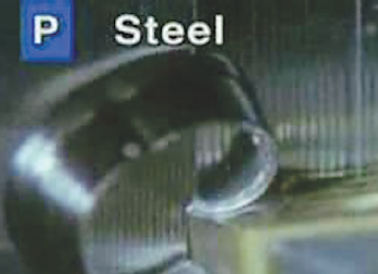
Notice the vertical lines, called tool marks, on the outside of the part being turned. As the feed rate increases, the distance between the lines also increases. The chip thickness is roughly equal to the feed.
Hold nut in vertical position and remove nut at an angle. Collet is automatically withdrawn from chuck by excentric ring of nut when unscrewed.
RD/ER Collets must be tightened correctly. Many machinists have been trained that nothing is ever too tight. This is particularly not true with collets and collet chucks. Overtightening a collet chuck will distort the collet and actually diminish the holding strength and accuracy. Maximum tightening torque for RD/ER Systems is as follows:
The high gripping strength RDO collet system was originated in Europe and are sometimes known as Ortlieb style collets or Full Grip Collets. Many machines designed for woodworking also use this system. This system is recommended for milling, drilling and boring applications. Many high production routing systems manufacturers have standardized on this system. Size Ranges are as follows:
Centaur also offers RDT/ER tapping collets. These collets will inexpensively convert a standard collet chuck into a length compensating, Quick-change tapping chuck with square drive.


 0086-813-8127573