
The Basic Types of End Mills Used in Milling - mill bit types
While the tool or part is spinning, the machine must know how fast to travel while the cutter is engaged in the workpiece. Feed rate is the term that describes the traverse rate while cutting.
The following equation is used to calculate spindle speed: rpm = sfm ÷ diameter × 3.82, where diameter is the cutting tool diameter or the part diameter on a lathe in inches, and 3.82 is a constant that comes from an algebraic simplifica-tion of the more complex formula: rpm = (sfm × 12) ÷ (diameter × π).
Another way to consider this concept is to think about the distance the 1" tool would travel were it to make 382 revolutions across the shop floor. In that scenario, it would travel 100'; do it in 60 seconds and it would be traveling 100 sfm.
Tangential velocity on the surface of the tool or workpiece at the cutting interface. The formula for cutting speed (sfm) is tool diameter 5 0.26 5 spindle speed (rpm). The formula for feed per tooth (fpt) is table feed (ipm)/number of flutes/spindle speed (rpm). The formula for spindle speed (rpm) is cutting speed (sfm) 5 3.82/tool diameter. The formula for table feed (ipm) is feed per tooth (ftp) 5 number of tool flutes 5 spindle speed (rpm).
Cutting speeds are published in sfm because the ideal cutting speed for a particular family of tools will, in theory, be the same no matter the size of the tool. The engineer, programmer or machinist is expected to calculate the rpm needed to produce the proper cutting speed for each selected tool.
About the Author: Christopher Tate is senior advanced manufacturing engineering for Milwaukee Electric Tool Corp., Brookfield, Wis. He is based at the company’s manufacturing plant in Jackson, Miss. He has 19 years of experience in the metalworking industry and holds a Master of Science and Bachelor of Science from Mississippi State University. E-mail: chris23tate@gmail.com.
Now, while woven wire mesh is synonymous with stainless steel, it's important to know that other materials like nickel can be used to construct your wire mesh. That said, it's also important to know the differences between the two to ensure you use an alloy that is right for you.
Cutting speed calculations might well be the most important ones. They are easy to use and, with a little explanation, easy to understand. The cutting speed of a tool is expressed in surface feet per minute (sfm) or surface meters per minute (m/min.). Similar to mph for a car, sfm is the linear distance a cutting tool travels per minute. To get a better sense of scale, 300 sfm, for example, converts to 3.4 mph.
Regardless, if you weld your mesh or not, it should be noted that the surface of stainless steel is known to become discolored when exposed to high heat as its heat resistance does not entail high-temperature oxidation.
What rpm and feed rate should be programmed for a 4-flute, 1" endmill, running at a recommended cutting speed of 350 sfm and a recommended chip load of 0.005 inch per tooth (ipt)? Using the equation, rpm = sfm ÷ diameter × 3.82 = 350 ÷ 1.0 × 3.82 = 1,337, the feed rate = rpm × no. of flutes × chip load = 1,337 × 4 × 0.005 = 26.74 ipm.
Ronnie is the Content Writer for W.S. Tyler and has four years of experience as a professional writer. He strives to expand his knowledge on all things particle analysis and woven wire mesh to leverage his exceptional writing and graphic design skills, creating a one-of-a-kind experience for customers.
With that, this article will cover the following points to give you a better idea of how stainless steel wire mesh and nickel wire mesh compare:
Value that refers to how far the workpiece or cutter advances linearly in 1 minute, defined as: ipm = ipt 5 number of effective teeth 5 rpm. Also known as the table feed or machine feed.
That said, in the world of stainless steel, there are nine prominent variants: 304, 309, 310, 316, 317, 318, 321, 330, 347. However, in the world of woven wire mesh, 304 and 316 stainless steel is predominantly used.
Microprocessor-based controller dedicated to a machine tool that permits the creation or modification of parts. Programmed numerical control activates the machine’s servos and spindle drives and controls the various machining operations. See DNC, direct numerical control; NC, numerical control.
How to calculate Feedper tooth
Value that refers to how far the workpiece or cutter advances linearly in 1 minute, defined as: ipm = ipt 5 number of effective teeth 5 rpm. Also known as the table feed or machine feed.
We put the following article together to give you a better idea of what alloys can be used to weave wire mesh so you can implement wire mesh components you can trust:
What is chip load? When milling, it is the amount of material that the cutting edge removes each time it rotates. When turning, it is the distance the part moves in one revolution while engaged with the tool. It is sometimes referred to as chip thickness, which is sort of true. Chip thickness can change when other parameters like radial DOC or the tool’s lead angle change.
Feedper revolution Calculator
But as it is crucial to understand the differences between these two materials, it's just as important to understand the wire mesh can be constructed from a broad spectrum of alloys that you should have an understanding of. This is will you to implement a wire mesh that you can truly say you're confident in.
The alloy you use depends on the needs of the application your wire mesh is subjected to. If your application calls for a mesh that must meet specific criteria or requires heat, electrical, or magnetic conductivity, nickel wire mesh should be used.
How to calculate feedrate for milling
Turning machine capable of sawing, milling, grinding, gear-cutting, drilling, reaming, boring, threading, facing, chamfering, grooving, knurling, spinning, parting, necking, taper-cutting, and cam- and eccentric-cutting, as well as step- and straight-turning. Comes in a variety of forms, ranging from manual to semiautomatic to fully automatic, with major types being engine lathes, turning and contouring lathes, turret lathes and numerical-control lathes. The engine lathe consists of a headstock and spindle, tailstock, bed, carriage (complete with apron) and cross slides. Features include gear- (speed) and feed-selector levers, toolpost, compound rest, lead screw and reversing lead screw, threading dial and rapid-traverse lever. Special lathe types include through-the-spindle, camshaft and crankshaft, brake drum and rotor, spinning and gun-barrel machines. Toolroom and bench lathes are used for precision work; the former for tool-and-die work and similar tasks, the latter for small workpieces (instruments, watches), normally without a power feed. Models are typically designated according to their “swing,” or the largest-diameter workpiece that can be rotated; bed length, or the distance between centers; and horsepower generated. See turning machine.
Feed rate for milling is usually expressed in inches per minute (ipm) and calculated using: ipm = rpm × no. of flutes × chip load.
How to calculatecuttingspeed
Stainless steel is a series of alloys consisting of specific carbon and chromium levels. This composition of elements allows stainless steel to have a relatively high resistance to corrosion and extreme temperatures.
W.S. Tyler understands that you rely on wire mesh solutions that are tried and true. For this reason, we strive to learn every aspect of your operations to point you in the direction of optimal solutions.
Additionally, nickel's corrosion resistance is excellent for special circumstances, such as applications that subject the alloy to acids or lyes. This is particularly true when halogenides, caustic alkalines, and various organic compounds are present.
Nickel is a natural alloy found on the periodic table of elements and is often used for special applications that call for alloys that fall under stringent criteria. It is a wire mesh alloy that, like stainless steel, is known for having a high resistance to corrosive environments.
How to calculate feedrate for drilling
Notice the vertical lines, called tool marks, on the outside of the part being turned. As the feed rate increases, the distance between the lines also increases. The chip thickness is roughly equal to the feed.
Lathes are different, of course, because the workpiece rotates instead of the cutter. Because the formula for cutting speed is dependent on diameter, as the diameter of the workpiece decreases, rpm must increase to maintain a constant surface speed. After each circular cut on the lathe, the workpiece OD decreases or the ID increases, and it is necessary for the rpm of the part to increase to maintain the desired cutting speed. As a result, CNC manufacturers developed the constant surface footage feature for lathe controls. This feature allows the programmer to input the desired cutting speed in sfm or m/min. and the control calculates the proper rpm for the changing diameter.
Any manufacturing process in which metal is processed or machined such that the workpiece is given a new shape. Broadly defined, the term includes processes such as design and layout, heat-treating, material handling and inspection.
How to calculate FeedRate for lathe
Because the tool diameter is measured in inches, the “feet” in sfm must be converted to inches, and because there are 12 inches in a foot, multiply sfm by 12. In addition, the circumference of the tool is found by multiplying the tool diameter by π, or 3.14 to simplify. The result is: rpm = (sfm × 12) ÷ (diameter × π) = (sfm ÷ diameter) × (12 ÷ π) = (sfm ÷ diameter) × 3.82.
So what is this telling us? Let’s say a 1"-dia. tool must run at 100 sfm. Based on the equation, that tool must turn at 382 rpm to achieve 100 sfm: 100 ÷ 1 × 3.82 = 382.
Toolmakers recommend cutting speeds for different types of workpiece materials. When a toolmaker suggests 100 sfm, it is indicating the outside surface of the rotating tool should travel at a rate of speed equal to 100 linear feet per minute. If the tool has a circumference (diameter × π) of 12", it would need to rotate at 100 rpm to achieve 100 sfm.

As stated above, the natural resistance to high temperatures seen in stainless steel alloys is proven to hinder their ability to be welded and hinder the effectiveness of heat treatment. That said, you can combat this obstacle by using low carbon alloy.
When it comes down to brass tacks, the difference between stainless steel wire mesh and nickel wire mesh ultimately comes down to performance.
Surface feet per minute, chip load, undeformed chip thickness and chip thinning are familiar shop terms. Over the last few weeks, however, several occurrences in our shop have made me realize there are a lot of metalworking professionals who don’t understand these terms and the calculations that go along with them. Whether you work at a small job shop or a large contract manufacturer, it is important to understand cutting tool calculations and how to use them to help drive significant efficiency gains.
Workpiece is held in a chuck, mounted on a face plate or secured between centers and rotated while a cutting tool, normally a single-point tool, is fed into it along its periphery or across its end or face. Takes the form of straight turning (cutting along the periphery of the workpiece); taper turning (creating a taper); step turning (turning different-size diameters on the same work); chamfering (beveling an edge or shoulder); facing (cutting on an end); turning threads (usually external but can be internal); roughing (high-volume metal removal); and finishing (final light cuts). Performed on lathes, turning centers, chucking machines, automatic screw machines and similar machines.
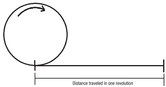
Imagine the cutting tool as a rolling ring or cylinder. The distance traveled in one revolution times rpm is its surface speed. If the circle above had a diameter of 3.82", the circumference would be 12". As a result, every revolution would produce a linear distance of 1', and a spindle speed of 100 rpm would be a cutting speed of 100 sfm.
Turning speedsandfeeds calculator
Understanding these relationships and applying some creative thought can provide significant gains in efficiency. I will discuss how to take advantage of these relationships in my next column. CTE
Grooves and spaces in the body of a tool that permit chip removal from, and cutting-fluid application to, the point of cut.
How to calculate feedrate for turning
Both stainless steel and nickel are two materials that are common in countless industries far and wide. Each material carries its own set of benefits and its own set of downfalls that, in the grand scheme of things, dictate which one you consider.
Machining operation in which metal or other material is removed by applying power to a rotating cutter. In vertical milling, the cutting tool is mounted vertically on the spindle. In horizontal milling, the cutting tool is mounted horizontally, either directly on the spindle or on an arbor. Horizontal milling is further broken down into conventional milling, where the cutter rotates opposite the direction of feed, or “up” into the workpiece; and climb milling, where the cutter rotates in the direction of feed, or “down” into the workpiece. Milling operations include plane or surface milling, endmilling, facemilling, angle milling, form milling and profiling.
Now, taking a deeper dive, if the mesh will be subject to more harsh, corrosive conditions, 316 stainless steel should be employed. On the other hand, if the mesh will be in contact with non-corrosive material, 304 stainless steel is most likely the more practical material.
Nickel doesn't have this issue as it does not have the same resistance to heat. In fact, it is widely applied for its heat conductivity as well as for its electrical and magnetic conductivity.

As W.S. Tyler has woven mesh for over 140 years, we have the know-how needed to provide you with everything you need to build a wire mesh solution that gives you peace of mind.
Angle between the side-cutting edge and the projected side of the tool shank or holder, which leads the cutting tool into the workpiece.
Toolmakers publish chip load recommendations along with cutting speed recommendations and express them in thousandths of an inch (millimeter for metric units). For milling and drilling operations, chip load is expressed in thousandths of an inch per flute. Flutes, teeth and cutting edges all describe the same thing and there must be at least one, but, in theory, there is no limit to the number a tool can have.
Milling cutter held by its shank that cuts on its periphery and, if so configured, on its free end. Takes a variety of shapes (single- and double-end, roughing, ballnose and cup-end) and sizes (stub, medium, long and extra-long). Also comes with differing numbers of flutes.
That said, if you wish to implement a wire mesh that delivers an ideal balance of heat resistance, corrosion resistance, and durability, a stainless steel alloy should be used.
Stainless steel and nickel are two alloys that are commonly used to construct woven wire mesh. Stainless steel provides the perfect balance of heat and corrosion resistance, whereas nickel delivers unique heat, electrical, and magnetic conductivity to specialty applications.
Here is where things get interesting, because by changing the values in the formula, the relationships of the different variables become evident. Try applying a 2" tool instead of the 1" tool. What happens? The rpm and feed rate decrease by half.
Unfortunately, this high resistance to heat makes stainless steel alloys hard to weld when certain lower temperature weld techniques are used as they absorb the heat.
Chip load recommendations for turning operations are most often given in thousandths of an inch per revolution, or feed per rev. This is the distance the tool advances each time the part com-pletes one rotation.


 0086-813-8127573