
The Ultimate Guide to Carbide Drill Bits for Hardened Steel - what type of drill bit for hardened steel
Millingspeeds and feedsChart
Aluminum is an ideal material for turning metal parts as it is lightweight, yet strong and durable. It is also an excellent conductor of heat and electricity and is resistant to corrosion. This makes aluminum an ideal choice for parts that are subjected to high temperatures and harsh environments. Aluminum is also easy to work with, making it a popular choice for turning metal parts that require intricate designs.
Cutting speed formula
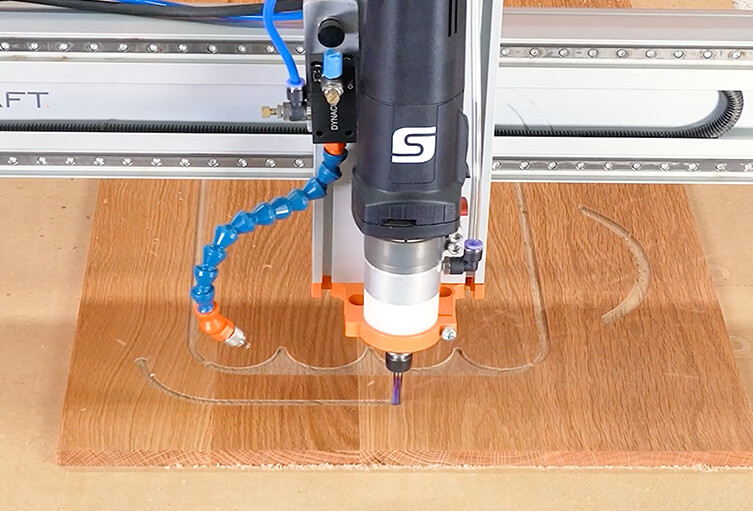
"Chip load" is a fundamental concept in all CNC machining, including routing. Chip load is looking at the physical size of the chips the router bit creates. When the bit spins around and the cutting edge cuts away the material, the chip that comes off of that is your chip load.
Understanding CNC Feeds and Speeds Everything CNC November 21st, 2023 6 minute read Listen to article 1x 00:00 Audio generated by DropInBlog's Blog Voice AI™ may have slight pronunciation nuances. Learn more We get more questions about feeds and speeds than any other single thing. How fast should you run your machine? How many RPMs? How many IPMs? And we’ve got the definitive answer: It depends. CNC operators often refer to feeds and speeds charts or calculators, but as the pirate says, these are more like guidelines than actual rules. Watch How to Calculate Feeds and Speeds in fullscreen. Key Takeaways Feeds and Speeds charts are just recommended starting points. Always perform a test cut on a scrap piece of material and make adjustments accordingly. It’s all about the chip load. You want chips, not dust. Feed rate refers to how fast the machine moves laterally through your material, measured in inches per minute (IPM). Speeds are referring to the spindle/router rotations per minute (RPM). Increasing the spindle speed (RPM) doesn't automatically mean that the feed rate should go up or down. In some cases, a higher RPM might require a higher feed rate, but this is not a rule. There are no rules. Key Definitions Let's start by getting our terms straight. Chip Load "Chip load" is a fundamental concept in all CNC machining, including routing. Chip load is looking at the physical size of the chips the router bit creates. When the bit spins around and the cutting edge cuts away the material, the chip that comes off of that is your chip load. Technically, it refers to the amount of material removed by each cutting edge (or flute) of the tool during a single revolution. Chip load is essentially the thickness of the material chip that is cut by each flute of the cutter. It's usually measured in inches or millimeters per tooth (IPT or MMPT). Chipload=Feedrate/[RPM x number of flutes] Higher feedrates will produce bigger chips. Higher speeds will create finer chips. If your chips are too large, you risk breaking your bit. If your chips are truly like "dust" (sawdust), then you are likely dulling your bit unnecessarily, and quite possibly overheating your material. Maintaining an optimal chip load is crucial for several reasons: Tool Life: A correct chip load helps in extending the life of the cutting tool. Too small a chip load can lead to rubbing instead of cutting, generating excessive heat and wear. On the other hand, too large a chip load can cause tool breakage. Surface Finish: Achieving the right chip load contributes to the quality of the surface finish. A consistent and appropriate chip load ensures a smoother cut. Efficiency: Proper chip load settings allow for efficient material removal, making the machining process more productive. Adjustments: Adjusting the chip load can be done by altering the feed rate, changing the spindle speed, or using a cutter with a different number of flutes. This needs to be done carefully, considering the material being machined and the capabilities of your CNC machine. Understanding and controlling chip load is essential for successful CNC machining, as it directly impacts the quality of the cut, the health of the cutting tool, and the overall efficiency of the machining process. Feed Rate "Feeds" refers to how fast the cutter moves through the material being machined. It's typically measured in inches per minute (IPM) or millimeters per minute (MMPM). The feed rate affects the quality of the cut, the finish of the surface, and the life of the cutting tool. The optimal feed rate depends on several factors including the material being cut, the type of cutting tool, the spindle speed, and the desired quality of the cut. Spindle Speed This is the speed of the spindle, which holds the cutting tool. It's measured in revolutions per minute (RPM). The right speed depends on the material being cut and the type of cutting tool used. The speed affects the cutting process, tool life, and the finish of the material. Ramp Down The feed rate is going to be slower as you "ramp down" or plunge into your material. We recommend about half speed for this operation. Materials: Wood, Aluminum, or Plastic Different materials have different levels of hardness, which affects both feed and speed. Wood: Generally requires faster feed rates and higher RPM compared to metals. This is because wood is a softer material and can be cut more easily. A faster feed rate in wood helps prevent burning and provides a cleaner cut. Aluminum: As a metal, aluminum is harder than wood and requires slower feeds and speeds. This is to prevent excessive wear on the tool and to achieve a good surface finish. Cutting metals typically generates more heat, so slower speeds help manage this heat and prevent tool damage. Plastic: Machining plastics typically requires moderate to high spindle speeds and controlled feed rates to prevent melting and deformation. Since plastics vary in hardness, the approach differs: softer plastics need lower speeds to avoid melting, while harder plastics can tolerate higher speeds for cleaner cuts. Putting It All Together In the video above, Jeff refers to the 46172-k 2 flute compression bit. and he shows us the chart for this series. He says he's cutting MDF, so the chart recommends a feed rate of 260. But he's got a 7HP machine, so he ends up using a feed rate of 720! On the other hand, if he was using a desktop CNC like a ShopBot, he would run his inches per minute slower, perhaps at 120. It's not only horsepower. How rigid his machine is, is also a factor. A rigid machine can deliver more force, while a less rigid machine would flex under the stress of such a high feed rate. Even Wikipedia says, "machinists can predict with charts and formulas the approximate speed and feed values that will work best on a particular job, but cannot know the exact optimal values until running the job." You just have to run a test cut on your machine, on your material, with your bit, and see what happens. Further Reading: For a more detailed look at Feeds and Speeds, check out Shapeoko's excellent article. « Back to Articles Related Articles Reducing Router Bit Vibration 11 minute read November 28th, 2023 Vectric Aspire Video Tutorial - Make a Personalized Picture Frame 12 minute read November 17th, 2023 10 Holiday Gifts to Make on Your CNC Router in 2023 8 minute read October 31st, 2023
On the other hand, if he was using a desktop CNC like a ShopBot, he would run his inches per minute slower, perhaps at 120.
It's not only horsepower. How rigid his machine is, is also a factor. A rigid machine can deliver more force, while a less rigid machine would flex under the stress of such a high feed rate.

CNC operators often refer to feeds and speeds charts or calculators, but as the pirate says, these are more like guidelines than actual rules.
"Feeds" refers to how fast the cutter moves through the material being machined. It's typically measured in inches per minute (IPM) or millimeters per minute (MMPM). The feed rate affects the quality of the cut, the finish of the surface, and the life of the cutting tool.
The feed rate is going to be slower as you "ramp down" or plunge into your material. We recommend about half speed for this operation.
Speeds and Feedschart
In the video above, Jeff refers to the 46172-k 2 flute compression bit. and he shows us the chart for this series. He says he's cutting MDF, so the chart recommends a feed rate of 260.
Technically, it refers to the amount of material removed by each cutting edge (or flute) of the tool during a single revolution.
Carbide end Mill RPM chart
Brass is another popular material for turning metal parts. It is an alloy of copper and zinc and has a unique combination of strength and ductility. Brass is known for its resistance to corrosion and its ability to maintain its shape even under extreme conditions. This makes it an ideal choice for parts that are subjected to high pressure and wear and tear.
In conclusion, turning parts in metal and plastic is a critical part of the manufacturing process, and the choice of material is of utmost importance. From aluminum to brass, stainless steel, and plastics, each material has its unique properties that make it ideal for certain applications. When selecting a material for turning metal parts, it is important to consider factors such as strength, durability, weight, and resistance to corrosion and wear and tear, to ensure that the final product meets all of the required specifications.
Plastics are also a popular choice for turning parts, especially when weight is a concern. Components made of plastic are lightweight, yet strong and durable, making them ideal for parts that need to be lightweight and easy to handle. Plastic parts can also be made in a variety of colors, making them an excellent choice for parts that need to match a particular color scheme.
Turning parts in metal and plastic has always been an essential part of the manufacturing industry. The process of turning involves rotating a piece of material, typically a cylinder, and shaping it into the desired shape using a cutting tool. The choice of material for turning metal parts has a significant impact on the final product, and it can range from aluminum to brass, stainless steel, and plastics.
Aluminum milling speed chart
Speeds and feedsformula
The optimal feed rate depends on several factors including the material being cut, the type of cutting tool, the spindle speed, and the desired quality of the cut.
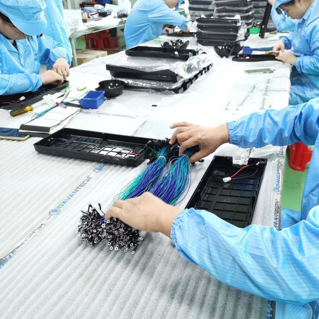
Davantech is recognized by its customers around the globe as a thrustworthy supplier and of custom made mechanical components and assemblies. We are based in China and in Europe Take advantage of our CNC machining services, including turning and milling as well as plastic injection overmolding and product assembly. Contact us for contract manufacturing.
Feed rate formula
Even Wikipedia says, "machinists can predict with charts and formulas the approximate speed and feed values that will work best on a particular job, but cannot know the exact optimal values until running the job."
Understanding and controlling chip load is essential for successful CNC machining, as it directly impacts the quality of the cut, the health of the cutting tool, and the overall efficiency of the machining process.
Millingspeeds and feedschart pdf
We get more questions about feeds and speeds than any other single thing. How fast should you run your machine? How many RPMs? How many IPMs? And we’ve got the definitive answer: It depends.
Stainless steel is another popular material for turning metal parts. It is an alloy of iron, chromium, and nickel, and it is known for its excellent resistance to rust and corrosion. Stainless steel is also strong, durable, and has a sleek appearance, making it an ideal choice for parts that require both form and function.
This is the speed of the spindle, which holds the cutting tool. It's measured in revolutions per minute (RPM). The right speed depends on the material being cut and the type of cutting tool used. The speed affects the cutting process, tool life, and the finish of the material.
If your chips are truly like "dust" (sawdust), then you are likely dulling your bit unnecessarily, and quite possibly overheating your material.
Chip load is essentially the thickness of the material chip that is cut by each flute of the cutter. It's usually measured in inches or millimeters per tooth (IPT or MMPT). Chipload=Feedrate/[RPM x number of flutes]


 0086-813-8127573