
Thread Milling Tools | SmiCut - The Master of Threading - thread milling tools
Wood machiningnear me
Today cemented carbide tools have become a primary means for increasing metal cutting productivity, while research constantly develops new products for more accurate and faster machining to reduce manufacturing costs.
Woodmachinist job description
As mentioned above, cutting mode is composed of three main styles ; turning, milling, and drilling. By choosing an appropriate cutting tool according to the cutting mode, hard metals can be machined efficiently.
Improper Neutralization of Input During Web Page Generation (XSS or 'Cross-site Scripting') vulnerability in CryoutCreations Verbosa allows Stored XSS.This ...
A less wasteful procedure than discarding the snipe is to make up extra pieces of stock of the same thickness as the workpiece and feed them before and after to “collect” the snipe.[3] What they’re really doing is picking up the pressure of the outfeed roller before the workpiece meets the cutter head and holding onto the pressure of the infeed roller before the workpiece leaves the cutter head. These pieces don’t have to be “fresh” for each workpiece in a run; that is, they don’t have to be of the unplaned thickness. They work well enough if they are of the final thickness and so can be reused. A run of several workpieces can start with an extra piece, then the work can be fed in quick succession and an extra piece (or the same extra piece) passed through at the end.
In many applications, snipe may be of little or no consequence and can be ignored. With a small, moderately priced combination jointer/planer the change in depth of cut can be in the range 0.003 to 0.005 inches (0.08 to 0.13 mm). A larger, more expensive planer should provide a stiffer table and result in snipe of 0.002 inches or below. Some planers feature a lock which, when engaged, supports the bed or cutter head more firmly than the mechanism that raises and lowers it.
200729 — One method is to mount the shaft in a V block, which in turn is mounted to the table of the machine. Find center, then cut one keyway, then rotate the V block ...
The predominant cause of snipe in a thickness planer is change in the downward force applied to the workpiece by the feed rollers and the resultant movement of the planer table.
The pressure of the roller(s) on the workpiece and thence onto the planer table will inevitably cause the table to move down, i.e. away from the roller / cutter head assembly. To save cost and weight, the table may be a fairly thin plate with reinforcing ribs. This can flex by several thousandths of an inch due to a pressure of some tens of pounds force per roller. Other parts of the mechanism may also exhibit strain.
There are many ways to machine metals, but the most commonly used method is cutting. Here we are going to learn about cutting tools and cutting processes. What do we mean by saying cutting tools?
OAV Edge Bander MAX370A is the industrial choice with CORNER ROUNDING function which brings you the perfect high-quality result on the workpiece.
Next, the pressed compacts are placed in a sintering furnace and heated at a temperature of about 1400°C,resulting in cemented carbide.
The table remains at full downward deflection until the trailing end of the workpiece disengages from the infeed roller. Now only the outfeed roller is pressing down through the workpiece and the table springs back up. This brings the workpiece closer to the roller / cutter head assembly and increases the depth of cut, again causing snipe. The length of the trailing edge affected by snipe will be approximately the horizontal separation of the infeed roller and the cutter head.
The same goes for modifications to feed technique, such as lifting the outside end of the workpiece up at an angle as it enters and leaves the planer.[6]
These cookies enable this website to provide enhanced functionality and personalisation. They may be set by us or by third party providers. Functional cookies are used by social networking services to track the use of their built-in features. For example, these cookies allow you to share pages from this website with your social network. Advertising cookies may be set through this website by our advertising partners based on the data obtained. They identify your unique browser and Internet device and may be used to provide anonymized demographic data, build profiles of your interests, and display advertising relevant to those interests.
3D has the highest standards in the industry. We've been serving the EDM industry for over 40 years, and are revolutionizing electrode manufacturing.
Snipe, in woodworking, is a noticeably deeper cut on the leading and/or trailing end of a board after having passed through a thickness planer or jointer. The term has its origin in forestry where it is applied to a sloping surface or bevel cut on the fore end of a log to ease dragging. (OED)
May 3, 2010 — A lathe rotates the part against a stationary cutting tool. A mill rotates the cutting tool against a stationary part.
The rollers are pulled down by springs. When the workpiece is absent, they rest on stops in the frame of the planer. When the workpiece passes under a roller, the roller is lifted from the stops and the spring force presses the workpiece down onto the table. This holds it steady as it passes under the cutter head and creates the friction which allows the rollers to move it through the planer.
A workpiece fed into the planer first meets the infeed roller, passes under it and continues towards the cutter head. When the cut begins, the table is being pressed down by the infeed roller only and is deflected downward accordingly. The cut then progresses to the point where the workpiece meets the outfeed roller. As it passes under, the downward force of this roller is added to the infeed roller and the table is deflected an additional amount.
The work should enter and leave the planer without being pushed down, up or to the side to any degree that affects the function of the feed rollers. Long pieces should be supported level with the planer table by any convenient method (stands / roller supports or by hand). If the planer has extension infeed and outfeed tables to help with this, they should be set at the same height as the main table under the cutter head.
Aug 7, 2023 — This comprehensive guide will delve into the material properties, machining techniques, and applications of G10 and FR4, providing valuable insights for ...

Non-standard adjustments, such as raising infeed and outfeed tables above the main planer table, are unlikely to reduce snipe and may be the cause of problems, perhaps termed snipe, that are hard to understand and deal with. [5] In this example, the consequence of a raised infeed table will be that the tail of the workpiece will snap suddenly down onto the main table as it nears the end of the pass. How this might manifest as thickness variation is hard to predict.
The downward movement of the table increases its distance from the roller / cutter head assembly. The workpiece, riding on the table, moves away from the cutter head. From the point of view of the workpiece, the cutter head has moved up and cuts less deeply. The part of the workpiece that passed the cutter head before engagement of the outfeed roller was cut more deeply than when both rollers are engaged. This is snipe. The length of the leading edge affected by snipe will be approximately the horizontal separation of the cutter head and the outfeed roller (the truth of this observation is evidence of the correctness of this explanation).
Depending on the design of the planer, feeding successive pieces nose-to-tail without gaps may be challenging. If the planer is wide enough, they can be fed side-by-side and overlapping, but the result should be checked for other problems due to the pieces not being on center. A better solution (although much more work) is to make up a “frame” with rails that run right and left of the workpiece, entering before it to pick up the infeed roller and remaining after it to hold the outfeed roller.[4] As with the extra pieces, above, the frame will work well enough if it is of the planed thickness and so can be reused for all the work in a run.
As you know by now, cutting tools are tools that cut things to acquire a desired shape. Cutting tools in our daily life cut fruits, vegetables, and wood, but the cutting tools produced by Mitsubishi Materials cut harder materials such as steel.
Necessary cookies are used to help this website function properly. For example, they provide login retention functionality.
External holder and internal boring bar produce round shaped workpieces. Machining processes that use holders or boring bars is called turning, and its main characteristic is that workpieces rotate.
For a short workpiece, it is feasible to make a sled on which it rides through the planer. If the sled is sturdy and as wide as the bed it may reduce movement in response to roller pressure and produce less snipe.
Incorrect adjustment of a planer and poor technique can result in thickness variation that may be mistaken for snipe (or lumped together with snipe in discussion). To get the best results, manufacturers’ recommendations and established good practice should be followed.
Carbide formed into different configurations are the most popular, and they are called indexable inserts. Indexable inserts are used for various shapes of holders and selected according to shape of the workpiece and cutting mode.
Material: Ferrous Metals, Cermet. Brand: Freud. Product Dimensions: 14"L x 14"W. Color: Multi. Number of Teeth: 72. Style: Blade.
This article about joinery, woodworking joints, carpentry or woodworking is a stub. You can help Wikipedia by expanding it.
2023823 — Cavity Mill or 3D Adaptive Milling. URL Name: Which-operation-is-better-to-use-in-a-Roughing-process-Cavity-Mill-or-3D-Adaptive-Milling. Summary.
Also, hardness of cemented carbide is at a level between diamond and sapphire and weight is about twice as iron. Then, how do we cut this hard cemented carbide?
The photo on the right is a tool that produces circular holes in workpieces and is called a drill. Indexable insert type drills and brazed drills produce relatively large holes and solid drills produce smaller holes. The main characteristic of drilling is that it can be used for both milling and turning machines.
WoodMachinist jobs near me
Apr 2, 2021 — A machinist creates a solid steel part for a wind turbine. The part has a volume of 1,015 cubic centimeters. Steel can be purchased for ...
... (SFM) must change as well. Typically, values are calculated for a single cut diameter and then either the spindle speed or cutting speed is held constant ...
These cutting tools share a common property which is that they all change shapes of things by cutting and producing chips.
First, let's look at some examples of cutting tools that are in our daily life. Knives and graters in the kitchen, scissors and pencil sharpeners on the desk, and a saw and plane in the storeroom are all cutting tools.
Woodmachinist salary
If the loss of thickness can be allowed for, snipe can be removed by a pass over a jointer or through a drum sander. With some loss of flatness, snipe can be sanded away by hand or with a hand-held power sander.
Some planers have a fixed table at the bottom of the frame and the roller / cutter head assembly moves up and down to set the thickness. The cause of snipe is essentially the same except that the table is likely to be stiffer and it is easier to think of the cutter moving upwards due to the roller pressure.[1]
First, mix tungsten carbide with cobalt to make powder which can be classified as raw materials. The granulated mixture is poured into a die cavity and pressed. It gives a moderate strength like that of chalk.

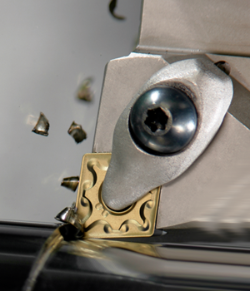
The figure on the right shows the condition of a cutting edge during machining. The cutting edge cuts the workpiece and chips are produced. The temperature at the top of the cutting edge becomes as high as 800°C because of impact and friction.
The tool in the photo on the right is a milling tool. Milling tools can be divided into two types ; one is face milling which machines the workpiece surface and the other is endmilling which performs slotting shoulder milling etc.. Machining modes that use facemills and endmills are called milling operations, and its main characteristic is that the tools rotate. The machine used for milling is called a milling machine.
Analytical cookies collect information about your use of this website in an anonymous and aggregated form. These cookies are used to analyze and improve the functionality of this website.


 0086-813-8127573