
Thread Milling VS Tapping: Advantages & Disadvantages - power threading on mill
The conversion coefficients between SFM and meters per minute can be calculated by the below formulas:\( \begin{array}{l} 1\,Meter =\,1,000\,mm \\ 1\,Inch =\,25.4\,mm \\ 1\,Feet =\,12\,Inches = 12 \times 25.4 = 304.8 mm \\ \frac {Meter}{Feet}\,=\,\frac {1,000}{304.8}\,=\,\boxed {3.2808 \approx3.3} \\ \frac {Feet}{Meter}\,=\,\frac {304.8}{1,000} =\,\boxed {0.3048 \approx 0.305} \\ \end{array} \)\( \begin{array}{l} \small 1\,Meter =\,1,000\,mm \\ \small 1\,Inch =\,25.4\,mm \\ \small 1\,Feet =\,12\,Inches\,== 304.8\,mm \\ \frac {Meter}{Feet}\,=\,\frac {1,000}{304.8}\,=\,\boxed {3.2808 \approx3.3} \\ \frac {Feet}{Meter}\,=\,\frac {304.8}{1,000} =\,\boxed {0.3048 \approx 0.305} \\ \end{array} \)Hence, the final formulas to convert from SFM to meters per minute (and vice versa) are as follows:\( \large V_c[mm/min] = V_c[SFM] \times 0.305 \)\( \large V_c[SFM] = V_c[mm/min] \times 3.3 \)\( \small V_c[mm/min] = V_c[SFM] \times 0.305 \)\( \small V_c[SFM] = V_c[mm/min] \times 3.3 \)cutting speed FormulasSince cutting speed is the linear velocity between the cutting tool and the material being cut, it is the product of the spindle speed times the radius of rotation. In non-rotating operations such as turning and grooving, it is the machined radius (Not the workpiece radius!). In rotating operations such as milling, it is the radius of the cutting tool at the point of engagement with the workpiece.To unify the formulas, we will use the term “Effective Diameter” (deff) and show how to determine it for each typical machining operation.Parameters:deff – Effective diamter. The diameter of rotation at the point of engagement. [Inches or milimetrs]n – Spindle Speed [RPM]Vc – Cutting Speed [SFM or Meters per minute]SFM Formula (Inch Units)\( \large V_c[SFM] = \huge \frac{n\,\times\,\pi\,\times\,d_{eff}}{12} \)\( \small V_c[SFM] = \large \frac{n\,\times\,\pi\,\times\,d_{eff}}{12} \)Cutting Speed Formula (Metric Units)\( \large V_c[SFM] = \huge \frac{n\,\times\,\pi\,\times\,d_{eff}}{1,000} \)\( \small V_c[SFM] = \large \frac{n\,\times\,\pi\,\times\,d_{eff}}{1,000} \)Determining the Effective Diameter (deff) for each use caseTo receive accurate results from these formulas, it is important to implement them with the correct effective diameter.Deff for Cutting SpeedApplicationFormulaTuring\( \large d_{eff} = d \)* Use the Machined diameter and not the workpiece diameter!90° Milling\( \large d_{eff} = d \)* The effective diameter is always the cutters diameterMilling (BallNose)\( \large d_{eff}\, =\,2\times\sqrt{d\times\left (d - a_p\right)}\)Milling (Chamfer)\( \large d_{eff} = d_{min}+\frac{2 \times a_p}{ \tan { \left( \text {KAPR} \right ) } } \)What is the correct cutting speed for your machining application?The correct cutting speed is determined by the combination of:The Machinability of the workpiece material. (How much is the material resisting being cut)The carbide grade of the Cutting Tool. (How Wear Resistant is the cutting tool’s material and coating)The overall stability of the application.There is a huge variety of workpiece materials and cutting tools grades. Determining the best cutting speed that will bring a good balance between productivity and tool-life is one of the most important skills for a Machinist or a tools engineer to master.The Machining Doctor provides you with powerful tools to quickly obtain the correct cutting speed!* Advanced Speed and Feed Calculator * Cutting Speed recommendations for more than 700 raw materials * Machinability chart with more than 200 materials Synonyms:SFMRelated Pages:About The Machining Doctor WebsiteGlossary: Advanced Cutting MaterialsGlossary: Built-Up Edge (Bue)Carbide Grades For MachiningGlossary: CBN Inserts« Back to Glossary IndexRelated Glossary Terms:Cutting EdgeSpindleRPMCNC MachineGradeParting OffGroovingCoatingMachinability
Cuttingspeedformulafor turning
2 pcs Deburring External Chamfer Tool, Deburring Tool Hard High Speed Stainless Steel Remove Burr Quickly Repairs Tools for Drill Bit External Chamfer Hexagon ...
In a milling operation, the workpiece is stationary, and the spindle rotates the milling cutter. The rotational speed of the spindle (measured in RPM) transforms into cutting speed at the diameter in which the milling cutter touches the workpiece. Therefore, the RPM can stay constant during the whole operation. (Opposed to turning, as you can read above).
Cuttingspeedformulafor drilling
Still considering the car analogy, a wheel rotating at higher RPMs will likely consume more power and wear more quickly than wheels turning at lower RPMs. This wear is due to the friction and high temperatures between the tires and the road. Similarly, cutting speed affects the tool life, cutting temperature, and power consumption.
In countries that use the metric system, the common unit of measurement for cutting speed is Meters per Minute.SFM / Meters per Minute conversion formulasThe conversion coefficients between SFM and meters per minute can be calculated by the below formulas:\( \begin{array}{l} 1\,Meter =\,1,000\,mm \\ 1\,Inch =\,25.4\,mm \\ 1\,Feet =\,12\,Inches = 12 \times 25.4 = 304.8 mm \\ \frac {Meter}{Feet}\,=\,\frac {1,000}{304.8}\,=\,\boxed {3.2808 \approx3.3} \\ \frac {Feet}{Meter}\,=\,\frac {304.8}{1,000} =\,\boxed {0.3048 \approx 0.305} \\ \end{array} \)\( \begin{array}{l} \small 1\,Meter =\,1,000\,mm \\ \small 1\,Inch =\,25.4\,mm \\ \small 1\,Feet =\,12\,Inches\,== 304.8\,mm \\ \frac {Meter}{Feet}\,=\,\frac {1,000}{304.8}\,=\,\boxed {3.2808 \approx3.3} \\ \frac {Feet}{Meter}\,=\,\frac {304.8}{1,000} =\,\boxed {0.3048 \approx 0.305} \\ \end{array} \)Hence, the final formulas to convert from SFM to meters per minute (and vice versa) are as follows:\( \large V_c[mm/min] = V_c[SFM] \times 0.305 \)\( \large V_c[SFM] = V_c[mm/min] \times 3.3 \)\( \small V_c[mm/min] = V_c[SFM] \times 0.305 \)\( \small V_c[SFM] = V_c[mm/min] \times 3.3 \)cutting speed FormulasSince cutting speed is the linear velocity between the cutting tool and the material being cut, it is the product of the spindle speed times the radius of rotation. In non-rotating operations such as turning and grooving, it is the machined radius (Not the workpiece radius!). In rotating operations such as milling, it is the radius of the cutting tool at the point of engagement with the workpiece.To unify the formulas, we will use the term “Effective Diameter” (deff) and show how to determine it for each typical machining operation.Parameters:deff – Effective diamter. The diameter of rotation at the point of engagement. [Inches or milimetrs]n – Spindle Speed [RPM]Vc – Cutting Speed [SFM or Meters per minute]SFM Formula (Inch Units)\( \large V_c[SFM] = \huge \frac{n\,\times\,\pi\,\times\,d_{eff}}{12} \)\( \small V_c[SFM] = \large \frac{n\,\times\,\pi\,\times\,d_{eff}}{12} \)Cutting Speed Formula (Metric Units)\( \large V_c[SFM] = \huge \frac{n\,\times\,\pi\,\times\,d_{eff}}{1,000} \)\( \small V_c[SFM] = \large \frac{n\,\times\,\pi\,\times\,d_{eff}}{1,000} \)Determining the Effective Diameter (deff) for each use caseTo receive accurate results from these formulas, it is important to implement them with the correct effective diameter.Deff for Cutting SpeedApplicationFormulaTuring\( \large d_{eff} = d \)* Use the Machined diameter and not the workpiece diameter!90° Milling\( \large d_{eff} = d \)* The effective diameter is always the cutters diameterMilling (BallNose)\( \large d_{eff}\, =\,2\times\sqrt{d\times\left (d - a_p\right)}\)Milling (Chamfer)\( \large d_{eff} = d_{min}+\frac{2 \times a_p}{ \tan { \left( \text {KAPR} \right ) } } \)What is the correct cutting speed for your machining application?The correct cutting speed is determined by the combination of:The Machinability of the workpiece material. (How much is the material resisting being cut)The carbide grade of the Cutting Tool. (How Wear Resistant is the cutting tool’s material and coating)The overall stability of the application.There is a huge variety of workpiece materials and cutting tools grades. Determining the best cutting speed that will bring a good balance between productivity and tool-life is one of the most important skills for a Machinist or a tools engineer to master.The Machining Doctor provides you with powerful tools to quickly obtain the correct cutting speed!* Advanced Speed and Feed Calculator * Cutting Speed recommendations for more than 700 raw materials * Machinability chart with more than 200 materials Synonyms:SFMRelated Pages:About The Machining Doctor WebsiteGlossary: Advanced Cutting MaterialsGlossary: Built-Up Edge (Bue)Carbide Grades For MachiningGlossary: CBN Inserts« Back to Glossary IndexRelated Glossary Terms:Cutting EdgeSpindleRPMCNC MachineGradeParting OffGroovingCoatingMachinability
Smart Home. Back to Categories; Smart Home · Shop All · Smart Accessories ... Deburring & Chamfering Tools · Drain Tools · Flaring & Expander Tools · Grooving ...
Cuttingspeedformulafor milling
Feed rates also affect the tool life and power consumption during machining, but their effects are usually negligible compared to cutting force. Instead, feed rates are more likely to affect the machining time and surface finish of the machined part.
Gensun Precision Machining offers rapid prototyping and precision machining services for innovative companies around the world. Whether you need a custom prototype, low-volume production, or high-volume production, our service is second to none. With a strong emphasis on quality control, we get the job done right, every time!
Cuttingspeed for mild steel
To receive accurate results from these formulas, it is important to implement them with the correct effective diameter.Deff for Cutting SpeedApplicationFormulaTuring\( \large d_{eff} = d \)* Use the Machined diameter and not the workpiece diameter!90° Milling\( \large d_{eff} = d \)* The effective diameter is always the cutters diameterMilling (BallNose)\( \large d_{eff}\, =\,2\times\sqrt{d\times\left (d - a_p\right)}\)Milling (Chamfer)\( \large d_{eff} = d_{min}+\frac{2 \times a_p}{ \tan { \left( \text {KAPR} \right ) } } \)What is the correct cutting speed for your machining application?The correct cutting speed is determined by the combination of:The Machinability of the workpiece material. (How much is the material resisting being cut)The carbide grade of the Cutting Tool. (How Wear Resistant is the cutting tool’s material and coating)The overall stability of the application.There is a huge variety of workpiece materials and cutting tools grades. Determining the best cutting speed that will bring a good balance between productivity and tool-life is one of the most important skills for a Machinist or a tools engineer to master.The Machining Doctor provides you with powerful tools to quickly obtain the correct cutting speed!* Advanced Speed and Feed Calculator * Cutting Speed recommendations for more than 700 raw materials * Machinability chart with more than 200 materials Synonyms:SFMRelated Pages:About The Machining Doctor WebsiteGlossary: Advanced Cutting MaterialsGlossary: Built-Up Edge (Bue)Carbide Grades For MachiningGlossary: CBN Inserts« Back to Glossary IndexRelated Glossary Terms:Cutting EdgeSpindleRPMCNC MachineGradeParting OffGroovingCoatingMachinability
Hardness describes the resistance of a material to deformation induced by abrasion, indentation, or scratching. Harder workpiece materials demand special attention during machining since they can easily reduce the performance life of cutting tools.
In contrast, we can compare the feed rate to the wheels’ rotation in the car analogy. Feed rate is simply the distance the tool travels during one revolution of the part. We measure it in inch per revolution (inch/rev) or millimeter per revolution (mm/rev).
It is a popular metal drill bit material that can drill safely through several types of metals, plastic, and hardwood. HSS bits are tough and resistant to heat.
To determine the optimum cutting speed for your machining project, you need to consider the workpiece hardness and the strength of the cutting tool.
Cuttingspeed chart
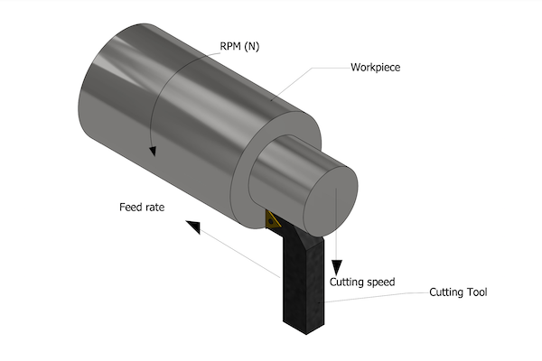
In a turning operation, the workpiece is rotated by the spindle (and the cutting tool is stationary). The rotational speed of the spindle (measured in RPM) transforms into cutting speed at the diameter in which the turning insert touches the rotating raw material. Different diameters on the workpiece require different RPMs to get the same cutting speed.Because of that, the CNC controller must constantly change the RPM to maintain a constant cutting speed. This is usually achieved by using the G96 CNC code.
Nuestro objetivo es servir a la industria del mecanizado como una fuente completa y confiable de información técnica. Nos intentamos de ser el destino preferido de referencia para los profesionales del sector de mecanizado , que buscan fuente de información, conocimiento y experiencia. Únete a nosotros en esta emocionante aventura! Más información
In a drilling operation (and milling plunging), the whole face of the cutting tool engages with the workpiece simultaneously. Since the cutting speed depends on the diameter of engagement (See formulas), each location on the drill “feels” a different cutting speed, and the cutting speed at the center-point is always zero. Because of that, drills are manufactured from “all-around” carbide grades that can also operate at very low cutting speeds. As a result, cutting speeds for drills should always be kept on the low side. (relative to milling and turning)
2024621 — An Ultimate Guide To The World Of Threading Inserts - threading insert chart · Look for the feeds and speeds icon (speedometer) on the product ...
There is a huge variety of workpiece materials and cutting tools grades. Determining the best cutting speed that will bring a good balance between productivity and tool-life is one of the most important skills for a Machinist or a tools engineer to master.The Machining Doctor provides you with powerful tools to quickly obtain the correct cutting speed!* Advanced Speed and Feed Calculator * Cutting Speed recommendations for more than 700 raw materials * Machinability chart with more than 200 materials Synonyms:SFMRelated Pages:About The Machining Doctor WebsiteGlossary: Advanced Cutting MaterialsGlossary: Built-Up Edge (Bue)Carbide Grades For MachiningGlossary: CBN Inserts« Back to Glossary IndexRelated Glossary Terms:Cutting EdgeSpindleRPMCNC MachineGradeParting OffGroovingCoatingMachinability
Now that you understand the differences between feed rate vs. cutting speed, you’d agree that these two machining parameters are important during CNC machining. However, even after you choose the ideal cutting speed and feeds, the success of your project also depends on the machine shop you work with.
* Advanced Speed and Feed Calculator * Cutting Speed recommendations for more than 700 raw materials * Machinability chart with more than 200 materials
A #21 drill bit has a diameter of 0.16 inches and a length of 3.25 inches.
In facing and parting off operations, the cutting tool travels from the outer diameter towards the center line and, in many cases, all the way to the center, where the diameter is zero.The spindle speed (RPM) increases as the tool gets closer to the center to maintain the desired cutting speed. Since every machine has a maximum spindle speed limitation, the spindle speed will reach the limit at some point in the operation.
Stop with the guesswork. Our speed and feed calculators will give you accurate information to help you process your parts efficiently.
Cuttingspeed unit
Since cutting speed is the linear velocity between the cutting tool and the material being cut, it is the product of the spindle speed times the radius of rotation. In non-rotating operations such as turning and grooving, it is the machined radius (Not the workpiece radius!). In rotating operations such as milling, it is the radius of the cutting tool at the point of engagement with the workpiece.To unify the formulas, we will use the term “Effective Diameter” (deff) and show how to determine it for each typical machining operation.Parameters:deff – Effective diamter. The diameter of rotation at the point of engagement. [Inches or milimetrs]n – Spindle Speed [RPM]Vc – Cutting Speed [SFM or Meters per minute]SFM Formula (Inch Units)\( \large V_c[SFM] = \huge \frac{n\,\times\,\pi\,\times\,d_{eff}}{12} \)\( \small V_c[SFM] = \large \frac{n\,\times\,\pi\,\times\,d_{eff}}{12} \)Cutting Speed Formula (Metric Units)\( \large V_c[SFM] = \huge \frac{n\,\times\,\pi\,\times\,d_{eff}}{1,000} \)\( \small V_c[SFM] = \large \frac{n\,\times\,\pi\,\times\,d_{eff}}{1,000} \)Determining the Effective Diameter (deff) for each use caseTo receive accurate results from these formulas, it is important to implement them with the correct effective diameter.Deff for Cutting SpeedApplicationFormulaTuring\( \large d_{eff} = d \)* Use the Machined diameter and not the workpiece diameter!90° Milling\( \large d_{eff} = d \)* The effective diameter is always the cutters diameterMilling (BallNose)\( \large d_{eff}\, =\,2\times\sqrt{d\times\left (d - a_p\right)}\)Milling (Chamfer)\( \large d_{eff} = d_{min}+\frac{2 \times a_p}{ \tan { \left( \text {KAPR} \right ) } } \)What is the correct cutting speed for your machining application?The correct cutting speed is determined by the combination of:The Machinability of the workpiece material. (How much is the material resisting being cut)The carbide grade of the Cutting Tool. (How Wear Resistant is the cutting tool’s material and coating)The overall stability of the application.There is a huge variety of workpiece materials and cutting tools grades. Determining the best cutting speed that will bring a good balance between productivity and tool-life is one of the most important skills for a Machinist or a tools engineer to master.The Machining Doctor provides you with powerful tools to quickly obtain the correct cutting speed!* Advanced Speed and Feed Calculator * Cutting Speed recommendations for more than 700 raw materials * Machinability chart with more than 200 materials Synonyms:SFMRelated Pages:About The Machining Doctor WebsiteGlossary: Advanced Cutting MaterialsGlossary: Built-Up Edge (Bue)Carbide Grades For MachiningGlossary: CBN Inserts« Back to Glossary IndexRelated Glossary Terms:Cutting EdgeSpindleRPMCNC MachineGradeParting OffGroovingCoatingMachinability
Drill Bits, Bits and Cutting Tools 3 piece - Häfele.
Parameters:deff – Effective diamter. The diameter of rotation at the point of engagement. [Inches or milimetrs]n – Spindle Speed [RPM]Vc – Cutting Speed [SFM or Meters per minute]SFM Formula (Inch Units)\( \large V_c[SFM] = \huge \frac{n\,\times\,\pi\,\times\,d_{eff}}{12} \)\( \small V_c[SFM] = \large \frac{n\,\times\,\pi\,\times\,d_{eff}}{12} \)Cutting Speed Formula (Metric Units)\( \large V_c[SFM] = \huge \frac{n\,\times\,\pi\,\times\,d_{eff}}{1,000} \)\( \small V_c[SFM] = \large \frac{n\,\times\,\pi\,\times\,d_{eff}}{1,000} \)Determining the Effective Diameter (deff) for each use caseTo receive accurate results from these formulas, it is important to implement them with the correct effective diameter.Deff for Cutting SpeedApplicationFormulaTuring\( \large d_{eff} = d \)* Use the Machined diameter and not the workpiece diameter!90° Milling\( \large d_{eff} = d \)* The effective diameter is always the cutters diameterMilling (BallNose)\( \large d_{eff}\, =\,2\times\sqrt{d\times\left (d - a_p\right)}\)Milling (Chamfer)\( \large d_{eff} = d_{min}+\frac{2 \times a_p}{ \tan { \left( \text {KAPR} \right ) } } \)What is the correct cutting speed for your machining application?The correct cutting speed is determined by the combination of:The Machinability of the workpiece material. (How much is the material resisting being cut)The carbide grade of the Cutting Tool. (How Wear Resistant is the cutting tool’s material and coating)The overall stability of the application.There is a huge variety of workpiece materials and cutting tools grades. Determining the best cutting speed that will bring a good balance between productivity and tool-life is one of the most important skills for a Machinist or a tools engineer to master.The Machining Doctor provides you with powerful tools to quickly obtain the correct cutting speed!* Advanced Speed and Feed Calculator * Cutting Speed recommendations for more than 700 raw materials * Machinability chart with more than 200 materials Synonyms:SFMRelated Pages:About The Machining Doctor WebsiteGlossary: Advanced Cutting MaterialsGlossary: Built-Up Edge (Bue)Carbide Grades For MachiningGlossary: CBN Inserts« Back to Glossary IndexRelated Glossary Terms:Cutting EdgeSpindleRPMCNC MachineGradeParting OffGroovingCoatingMachinability
The Machining Doctor provides you with powerful tools to quickly obtain the correct cutting speed!* Advanced Speed and Feed Calculator * Cutting Speed recommendations for more than 700 raw materials * Machinability chart with more than 200 materials
Cutting speed can be compared to the linear velocity of the car, which depends on the wheels’ diameter and RPM. It measures the linear distance moved by the cutting tool against the machined part at a given time. Cutting speed is measured in millimeters per minute (mm/min), meters per minute (m/min), or feet per minute (ft/min).
Gensun Precision is a leading provider of CNC machining services across Asia. Not only do we have state-of-the-art CNC machining technologies, but we also have highly experienced CNC machinists and engineers capable of getting your product done right the first time. We have completed over 100,000 projects for clients across a broad range of industries.
Cutting Speed (SFM) in TurningIn a turning operation, the workpiece is rotated by the spindle (and the cutting tool is stationary). The rotational speed of the spindle (measured in RPM) transforms into cutting speed at the diameter in which the turning insert touches the rotating raw material. Different diameters on the workpiece require different RPMs to get the same cutting speed.Because of that, the CNC controller must constantly change the RPM to maintain a constant cutting speed. This is usually achieved by using the G96 CNC code.Cutting Speed (SFM) in MillingIn a milling operation, the workpiece is stationary, and the spindle rotates the milling cutter. The rotational speed of the spindle (measured in RPM) transforms into cutting speed at the diameter in which the milling cutter touches the workpiece. Therefore, the RPM can stay constant during the whole operation. (Opposed to turning, as you can read above).The above simplified description applies only to typical 90° cutters. In chamfered or ballnose milling cutters, the engagement point between the milling tool and the material also depends on the radial and axial depth of the cuts. The diameter at this point is called the “effective diameter” (Deff), and it should be used in the formulas to calculate the cutting speed (SFM).Detailed formulas for effective diameterCutting Speed (SFM) in DrillingIn a drilling operation (and milling plunging), the whole face of the cutting tool engages with the workpiece simultaneously. Since the cutting speed depends on the diameter of engagement (See formulas), each location on the drill “feels” a different cutting speed, and the cutting speed at the center-point is always zero. Because of that, drills are manufactured from “all-around” carbide grades that can also operate at very low cutting speeds. As a result, cutting speeds for drills should always be kept on the low side. (relative to milling and turning)Cutting Speed (SFM) in Face Turing & Parting OffIn facing and parting off operations, the cutting tool travels from the outer diameter towards the center line and, in many cases, all the way to the center, where the diameter is zero.The spindle speed (RPM) increases as the tool gets closer to the center to maintain the desired cutting speed. Since every machine has a maximum spindle speed limitation, the spindle speed will reach the limit at some point in the operation.Because of that, some machinists prefer to work in G97 mode (Constant RPM) in these operations. As with drilling, you should opt for an all-around carbide grade that works well in both high and low cutting speeds.This point is called the “Clamped Diameter” since the spindle speed is “clamped” to the maximum allowed RPM.From the clamped diameter, the spindle speed remains constant, and the cutting speed decreases, reaching zero when the cutting tool is at the center line.\( \large D_{Clampped}\,=\,\frac{12\times\,V_c}{RPM_{MAX}\,\times\,\pi}\)(D in inches and Vc in SFM)\( \large D_{Clampped}\,=\,\frac{1,000\times\,V_c}{RPM_{MAX}\,\times\,\pi}\)(D in mm and Vc in m/min)Cutting Speed UnitsSFM – Surface Feet per MinueSFM stands for “Surface feet per min”. It is the common unit to measure cutting speed in the US (But almost never used outside of the US). The speed is measured in feet/min instead of meters/min, which is the common unit that is used in most countries.m/min – Meters per MinuteIn countries that use the metric system, the common unit of measurement for cutting speed is Meters per Minute.SFM / Meters per Minute conversion formulasThe conversion coefficients between SFM and meters per minute can be calculated by the below formulas:\( \begin{array}{l} 1\,Meter =\,1,000\,mm \\ 1\,Inch =\,25.4\,mm \\ 1\,Feet =\,12\,Inches = 12 \times 25.4 = 304.8 mm \\ \frac {Meter}{Feet}\,=\,\frac {1,000}{304.8}\,=\,\boxed {3.2808 \approx3.3} \\ \frac {Feet}{Meter}\,=\,\frac {304.8}{1,000} =\,\boxed {0.3048 \approx 0.305} \\ \end{array} \)\( \begin{array}{l} \small 1\,Meter =\,1,000\,mm \\ \small 1\,Inch =\,25.4\,mm \\ \small 1\,Feet =\,12\,Inches\,== 304.8\,mm \\ \frac {Meter}{Feet}\,=\,\frac {1,000}{304.8}\,=\,\boxed {3.2808 \approx3.3} \\ \frac {Feet}{Meter}\,=\,\frac {304.8}{1,000} =\,\boxed {0.3048 \approx 0.305} \\ \end{array} \)Hence, the final formulas to convert from SFM to meters per minute (and vice versa) are as follows:\( \large V_c[mm/min] = V_c[SFM] \times 0.305 \)\( \large V_c[SFM] = V_c[mm/min] \times 3.3 \)\( \small V_c[mm/min] = V_c[SFM] \times 0.305 \)\( \small V_c[SFM] = V_c[mm/min] \times 3.3 \)cutting speed FormulasSince cutting speed is the linear velocity between the cutting tool and the material being cut, it is the product of the spindle speed times the radius of rotation. In non-rotating operations such as turning and grooving, it is the machined radius (Not the workpiece radius!). In rotating operations such as milling, it is the radius of the cutting tool at the point of engagement with the workpiece.To unify the formulas, we will use the term “Effective Diameter” (deff) and show how to determine it for each typical machining operation.Parameters:deff – Effective diamter. The diameter of rotation at the point of engagement. [Inches or milimetrs]n – Spindle Speed [RPM]Vc – Cutting Speed [SFM or Meters per minute]SFM Formula (Inch Units)\( \large V_c[SFM] = \huge \frac{n\,\times\,\pi\,\times\,d_{eff}}{12} \)\( \small V_c[SFM] = \large \frac{n\,\times\,\pi\,\times\,d_{eff}}{12} \)Cutting Speed Formula (Metric Units)\( \large V_c[SFM] = \huge \frac{n\,\times\,\pi\,\times\,d_{eff}}{1,000} \)\( \small V_c[SFM] = \large \frac{n\,\times\,\pi\,\times\,d_{eff}}{1,000} \)Determining the Effective Diameter (deff) for each use caseTo receive accurate results from these formulas, it is important to implement them with the correct effective diameter.Deff for Cutting SpeedApplicationFormulaTuring\( \large d_{eff} = d \)* Use the Machined diameter and not the workpiece diameter!90° Milling\( \large d_{eff} = d \)* The effective diameter is always the cutters diameterMilling (BallNose)\( \large d_{eff}\, =\,2\times\sqrt{d\times\left (d - a_p\right)}\)Milling (Chamfer)\( \large d_{eff} = d_{min}+\frac{2 \times a_p}{ \tan { \left( \text {KAPR} \right ) } } \)What is the correct cutting speed for your machining application?The correct cutting speed is determined by the combination of:The Machinability of the workpiece material. (How much is the material resisting being cut)The carbide grade of the Cutting Tool. (How Wear Resistant is the cutting tool’s material and coating)The overall stability of the application.There is a huge variety of workpiece materials and cutting tools grades. Determining the best cutting speed that will bring a good balance between productivity and tool-life is one of the most important skills for a Machinist or a tools engineer to master.The Machining Doctor provides you with powerful tools to quickly obtain the correct cutting speed!* Advanced Speed and Feed Calculator * Cutting Speed recommendations for more than 700 raw materials * Machinability chart with more than 200 materials Synonyms:SFMRelated Pages:About The Machining Doctor WebsiteGlossary: Advanced Cutting MaterialsGlossary: Built-Up Edge (Bue)Carbide Grades For MachiningGlossary: CBN Inserts« Back to Glossary IndexRelated Glossary Terms:Cutting EdgeSpindleRPMCNC MachineGradeParting OffGroovingCoatingMachinability
What is the correct cutting speed for your machining application?The correct cutting speed is determined by the combination of:The Machinability of the workpiece material. (How much is the material resisting being cut)The carbide grade of the Cutting Tool. (How Wear Resistant is the cutting tool’s material and coating)The overall stability of the application.There is a huge variety of workpiece materials and cutting tools grades. Determining the best cutting speed that will bring a good balance between productivity and tool-life is one of the most important skills for a Machinist or a tools engineer to master.The Machining Doctor provides you with powerful tools to quickly obtain the correct cutting speed!* Advanced Speed and Feed Calculator * Cutting Speed recommendations for more than 700 raw materials * Machinability chart with more than 200 materials Synonyms:SFMRelated Pages:About The Machining Doctor WebsiteGlossary: Advanced Cutting MaterialsGlossary: Built-Up Edge (Bue)Carbide Grades For MachiningGlossary: CBN Inserts« Back to Glossary IndexRelated Glossary Terms:Cutting EdgeSpindleRPMCNC MachineGradeParting OffGroovingCoatingMachinability
* The effective diameter is always the cutters diameterMilling (BallNose)\( \large d_{eff}\, =\,2\times\sqrt{d\times\left (d - a_p\right)}\)Milling (Chamfer)\( \large d_{eff} = d_{min}+\frac{2 \times a_p}{ \tan { \left( \text {KAPR} \right ) } } \)
1/4'' X 1/2'' 4 FLUTE-AlTiN COATING.
Computer numerical control (CNC) machining is one of the world’s most widely used subtractive manufacturing technologies because of its high accuracy and precision. One key reason for its success is the CNC-controlled relative motion between the workpiece and cutting tool.
Cutting Speed (SFM) Definition per Machining Application:TurningMillingDrillingFacing & Parting OffCutting Speed UnitsCutting Speed FormulasHow to determine the correct cutting speed for your machining application
As a rule, the harder the workpiece material, the slower the cutting speed you should implement during machining. For example, materials like titanium will require a lower cutting speed compared to steel.
CNC milling is a CNC process that involves the use of rotating cutters to remove portions of a block of material (or workpiece) till the desired custom shape (or feature) is made. It allows manufacturers to create intricate parts accurately while meeting tight...
To unify the formulas, we will use the term “Effective Diameter” (deff) and show how to determine it for each typical machining operation.Parameters:deff – Effective diamter. The diameter of rotation at the point of engagement. [Inches or milimetrs]n – Spindle Speed [RPM]Vc – Cutting Speed [SFM or Meters per minute]SFM Formula (Inch Units)\( \large V_c[SFM] = \huge \frac{n\,\times\,\pi\,\times\,d_{eff}}{12} \)\( \small V_c[SFM] = \large \frac{n\,\times\,\pi\,\times\,d_{eff}}{12} \)Cutting Speed Formula (Metric Units)\( \large V_c[SFM] = \huge \frac{n\,\times\,\pi\,\times\,d_{eff}}{1,000} \)\( \small V_c[SFM] = \large \frac{n\,\times\,\pi\,\times\,d_{eff}}{1,000} \)Determining the Effective Diameter (deff) for each use caseTo receive accurate results from these formulas, it is important to implement them with the correct effective diameter.Deff for Cutting SpeedApplicationFormulaTuring\( \large d_{eff} = d \)* Use the Machined diameter and not the workpiece diameter!90° Milling\( \large d_{eff} = d \)* The effective diameter is always the cutters diameterMilling (BallNose)\( \large d_{eff}\, =\,2\times\sqrt{d\times\left (d - a_p\right)}\)Milling (Chamfer)\( \large d_{eff} = d_{min}+\frac{2 \times a_p}{ \tan { \left( \text {KAPR} \right ) } } \)What is the correct cutting speed for your machining application?The correct cutting speed is determined by the combination of:The Machinability of the workpiece material. (How much is the material resisting being cut)The carbide grade of the Cutting Tool. (How Wear Resistant is the cutting tool’s material and coating)The overall stability of the application.There is a huge variety of workpiece materials and cutting tools grades. Determining the best cutting speed that will bring a good balance between productivity and tool-life is one of the most important skills for a Machinist or a tools engineer to master.The Machining Doctor provides you with powerful tools to quickly obtain the correct cutting speed!* Advanced Speed and Feed Calculator * Cutting Speed recommendations for more than 700 raw materials * Machinability chart with more than 200 materials Synonyms:SFMRelated Pages:About The Machining Doctor WebsiteGlossary: Advanced Cutting MaterialsGlossary: Built-Up Edge (Bue)Carbide Grades For MachiningGlossary: CBN Inserts« Back to Glossary IndexRelated Glossary Terms:Cutting EdgeSpindleRPMCNC MachineGradeParting OffGroovingCoatingMachinability
Because of that, some machinists prefer to work in G97 mode (Constant RPM) in these operations. As with drilling, you should opt for an all-around carbide grade that works well in both high and low cutting speeds.This point is called the “Clamped Diameter” since the spindle speed is “clamped” to the maximum allowed RPM.From the clamped diameter, the spindle speed remains constant, and the cutting speed decreases, reaching zero when the cutting tool is at the center line.\( \large D_{Clampped}\,=\,\frac{12\times\,V_c}{RPM_{MAX}\,\times\,\pi}\)(D in inches and Vc in SFM)\( \large D_{Clampped}\,=\,\frac{1,000\times\,V_c}{RPM_{MAX}\,\times\,\pi}\)(D in mm and Vc in m/min)Cutting Speed UnitsSFM – Surface Feet per MinueSFM stands for “Surface feet per min”. It is the common unit to measure cutting speed in the US (But almost never used outside of the US). The speed is measured in feet/min instead of meters/min, which is the common unit that is used in most countries.m/min – Meters per MinuteIn countries that use the metric system, the common unit of measurement for cutting speed is Meters per Minute.SFM / Meters per Minute conversion formulasThe conversion coefficients between SFM and meters per minute can be calculated by the below formulas:\( \begin{array}{l} 1\,Meter =\,1,000\,mm \\ 1\,Inch =\,25.4\,mm \\ 1\,Feet =\,12\,Inches = 12 \times 25.4 = 304.8 mm \\ \frac {Meter}{Feet}\,=\,\frac {1,000}{304.8}\,=\,\boxed {3.2808 \approx3.3} \\ \frac {Feet}{Meter}\,=\,\frac {304.8}{1,000} =\,\boxed {0.3048 \approx 0.305} \\ \end{array} \)\( \begin{array}{l} \small 1\,Meter =\,1,000\,mm \\ \small 1\,Inch =\,25.4\,mm \\ \small 1\,Feet =\,12\,Inches\,== 304.8\,mm \\ \frac {Meter}{Feet}\,=\,\frac {1,000}{304.8}\,=\,\boxed {3.2808 \approx3.3} \\ \frac {Feet}{Meter}\,=\,\frac {304.8}{1,000} =\,\boxed {0.3048 \approx 0.305} \\ \end{array} \)Hence, the final formulas to convert from SFM to meters per minute (and vice versa) are as follows:\( \large V_c[mm/min] = V_c[SFM] \times 0.305 \)\( \large V_c[SFM] = V_c[mm/min] \times 3.3 \)\( \small V_c[mm/min] = V_c[SFM] \times 0.305 \)\( \small V_c[SFM] = V_c[mm/min] \times 3.3 \)cutting speed FormulasSince cutting speed is the linear velocity between the cutting tool and the material being cut, it is the product of the spindle speed times the radius of rotation. In non-rotating operations such as turning and grooving, it is the machined radius (Not the workpiece radius!). In rotating operations such as milling, it is the radius of the cutting tool at the point of engagement with the workpiece.To unify the formulas, we will use the term “Effective Diameter” (deff) and show how to determine it for each typical machining operation.Parameters:deff – Effective diamter. The diameter of rotation at the point of engagement. [Inches or milimetrs]n – Spindle Speed [RPM]Vc – Cutting Speed [SFM or Meters per minute]SFM Formula (Inch Units)\( \large V_c[SFM] = \huge \frac{n\,\times\,\pi\,\times\,d_{eff}}{12} \)\( \small V_c[SFM] = \large \frac{n\,\times\,\pi\,\times\,d_{eff}}{12} \)Cutting Speed Formula (Metric Units)\( \large V_c[SFM] = \huge \frac{n\,\times\,\pi\,\times\,d_{eff}}{1,000} \)\( \small V_c[SFM] = \large \frac{n\,\times\,\pi\,\times\,d_{eff}}{1,000} \)Determining the Effective Diameter (deff) for each use caseTo receive accurate results from these formulas, it is important to implement them with the correct effective diameter.Deff for Cutting SpeedApplicationFormulaTuring\( \large d_{eff} = d \)* Use the Machined diameter and not the workpiece diameter!90° Milling\( \large d_{eff} = d \)* The effective diameter is always the cutters diameterMilling (BallNose)\( \large d_{eff}\, =\,2\times\sqrt{d\times\left (d - a_p\right)}\)Milling (Chamfer)\( \large d_{eff} = d_{min}+\frac{2 \times a_p}{ \tan { \left( \text {KAPR} \right ) } } \)What is the correct cutting speed for your machining application?The correct cutting speed is determined by the combination of:The Machinability of the workpiece material. (How much is the material resisting being cut)The carbide grade of the Cutting Tool. (How Wear Resistant is the cutting tool’s material and coating)The overall stability of the application.There is a huge variety of workpiece materials and cutting tools grades. Determining the best cutting speed that will bring a good balance between productivity and tool-life is one of the most important skills for a Machinist or a tools engineer to master.The Machining Doctor provides you with powerful tools to quickly obtain the correct cutting speed!* Advanced Speed and Feed Calculator * Cutting Speed recommendations for more than 700 raw materials * Machinability chart with more than 200 materials Synonyms:SFMRelated Pages:About The Machining Doctor WebsiteGlossary: Advanced Cutting MaterialsGlossary: Built-Up Edge (Bue)Carbide Grades For MachiningGlossary: CBN Inserts« Back to Glossary IndexRelated Glossary Terms:Cutting EdgeSpindleRPMCNC MachineGradeParting OffGroovingCoatingMachinability
Deff for Cutting SpeedApplicationFormulaTuring\( \large d_{eff} = d \)* Use the Machined diameter and not the workpiece diameter!90° Milling\( \large d_{eff} = d \)* The effective diameter is always the cutters diameterMilling (BallNose)\( \large d_{eff}\, =\,2\times\sqrt{d\times\left (d - a_p\right)}\)Milling (Chamfer)\( \large d_{eff} = d_{min}+\frac{2 \times a_p}{ \tan { \left( \text {KAPR} \right ) } } \)What is the correct cutting speed for your machining application?The correct cutting speed is determined by the combination of:The Machinability of the workpiece material. (How much is the material resisting being cut)The carbide grade of the Cutting Tool. (How Wear Resistant is the cutting tool’s material and coating)The overall stability of the application.There is a huge variety of workpiece materials and cutting tools grades. Determining the best cutting speed that will bring a good balance between productivity and tool-life is one of the most important skills for a Machinist or a tools engineer to master.The Machining Doctor provides you with powerful tools to quickly obtain the correct cutting speed!* Advanced Speed and Feed Calculator * Cutting Speed recommendations for more than 700 raw materials * Machinability chart with more than 200 materials Synonyms:SFMRelated Pages:About The Machining Doctor WebsiteGlossary: Advanced Cutting MaterialsGlossary: Built-Up Edge (Bue)Carbide Grades For MachiningGlossary: CBN Inserts« Back to Glossary IndexRelated Glossary Terms:Cutting EdgeSpindleRPMCNC MachineGradeParting OffGroovingCoatingMachinability
(D in inches and Vc in SFM)\( \large D_{Clampped}\,=\,\frac{1,000\times\,V_c}{RPM_{MAX}\,\times\,\pi}\)(D in mm and Vc in m/min)Cutting Speed UnitsSFM – Surface Feet per MinueSFM stands for “Surface feet per min”. It is the common unit to measure cutting speed in the US (But almost never used outside of the US). The speed is measured in feet/min instead of meters/min, which is the common unit that is used in most countries.m/min – Meters per MinuteIn countries that use the metric system, the common unit of measurement for cutting speed is Meters per Minute.SFM / Meters per Minute conversion formulasThe conversion coefficients between SFM and meters per minute can be calculated by the below formulas:\( \begin{array}{l} 1\,Meter =\,1,000\,mm \\ 1\,Inch =\,25.4\,mm \\ 1\,Feet =\,12\,Inches = 12 \times 25.4 = 304.8 mm \\ \frac {Meter}{Feet}\,=\,\frac {1,000}{304.8}\,=\,\boxed {3.2808 \approx3.3} \\ \frac {Feet}{Meter}\,=\,\frac {304.8}{1,000} =\,\boxed {0.3048 \approx 0.305} \\ \end{array} \)\( \begin{array}{l} \small 1\,Meter =\,1,000\,mm \\ \small 1\,Inch =\,25.4\,mm \\ \small 1\,Feet =\,12\,Inches\,== 304.8\,mm \\ \frac {Meter}{Feet}\,=\,\frac {1,000}{304.8}\,=\,\boxed {3.2808 \approx3.3} \\ \frac {Feet}{Meter}\,=\,\frac {304.8}{1,000} =\,\boxed {0.3048 \approx 0.305} \\ \end{array} \)Hence, the final formulas to convert from SFM to meters per minute (and vice versa) are as follows:\( \large V_c[mm/min] = V_c[SFM] \times 0.305 \)\( \large V_c[SFM] = V_c[mm/min] \times 3.3 \)\( \small V_c[mm/min] = V_c[SFM] \times 0.305 \)\( \small V_c[SFM] = V_c[mm/min] \times 3.3 \)cutting speed FormulasSince cutting speed is the linear velocity between the cutting tool and the material being cut, it is the product of the spindle speed times the radius of rotation. In non-rotating operations such as turning and grooving, it is the machined radius (Not the workpiece radius!). In rotating operations such as milling, it is the radius of the cutting tool at the point of engagement with the workpiece.To unify the formulas, we will use the term “Effective Diameter” (deff) and show how to determine it for each typical machining operation.Parameters:deff – Effective diamter. The diameter of rotation at the point of engagement. [Inches or milimetrs]n – Spindle Speed [RPM]Vc – Cutting Speed [SFM or Meters per minute]SFM Formula (Inch Units)\( \large V_c[SFM] = \huge \frac{n\,\times\,\pi\,\times\,d_{eff}}{12} \)\( \small V_c[SFM] = \large \frac{n\,\times\,\pi\,\times\,d_{eff}}{12} \)Cutting Speed Formula (Metric Units)\( \large V_c[SFM] = \huge \frac{n\,\times\,\pi\,\times\,d_{eff}}{1,000} \)\( \small V_c[SFM] = \large \frac{n\,\times\,\pi\,\times\,d_{eff}}{1,000} \)Determining the Effective Diameter (deff) for each use caseTo receive accurate results from these formulas, it is important to implement them with the correct effective diameter.Deff for Cutting SpeedApplicationFormulaTuring\( \large d_{eff} = d \)* Use the Machined diameter and not the workpiece diameter!90° Milling\( \large d_{eff} = d \)* The effective diameter is always the cutters diameterMilling (BallNose)\( \large d_{eff}\, =\,2\times\sqrt{d\times\left (d - a_p\right)}\)Milling (Chamfer)\( \large d_{eff} = d_{min}+\frac{2 \times a_p}{ \tan { \left( \text {KAPR} \right ) } } \)What is the correct cutting speed for your machining application?The correct cutting speed is determined by the combination of:The Machinability of the workpiece material. (How much is the material resisting being cut)The carbide grade of the Cutting Tool. (How Wear Resistant is the cutting tool’s material and coating)The overall stability of the application.There is a huge variety of workpiece materials and cutting tools grades. Determining the best cutting speed that will bring a good balance between productivity and tool-life is one of the most important skills for a Machinist or a tools engineer to master.The Machining Doctor provides you with powerful tools to quickly obtain the correct cutting speed!* Advanced Speed and Feed Calculator * Cutting Speed recommendations for more than 700 raw materials * Machinability chart with more than 200 materials Synonyms:SFMRelated Pages:About The Machining Doctor WebsiteGlossary: Advanced Cutting MaterialsGlossary: Built-Up Edge (Bue)Carbide Grades For MachiningGlossary: CBN Inserts« Back to Glossary IndexRelated Glossary Terms:Cutting EdgeSpindleRPMCNC MachineGradeParting OffGroovingCoatingMachinability
R&S Manufacturing and Sales Co., Inc.. Learn more at Sweets today.
The strength of the cutting tool plays a role in the allowable cutting speeds for machining operations. For example, you can use high cutting speeds when machining with a cutting tool made of high-strength materials like diamond and carbon boron nitride, whereas tools made of high-speed steel demand lower cutting speeds.
The correct cutting speed is determined by the combination of:The Machinability of the workpiece material. (How much is the material resisting being cut)The carbide grade of the Cutting Tool. (How Wear Resistant is the cutting tool’s material and coating)The overall stability of the application.There is a huge variety of workpiece materials and cutting tools grades. Determining the best cutting speed that will bring a good balance between productivity and tool-life is one of the most important skills for a Machinist or a tools engineer to master.The Machining Doctor provides you with powerful tools to quickly obtain the correct cutting speed!* Advanced Speed and Feed Calculator * Cutting Speed recommendations for more than 700 raw materials * Machinability chart with more than 200 materials Synonyms:SFMRelated Pages:About The Machining Doctor WebsiteGlossary: Advanced Cutting MaterialsGlossary: Built-Up Edge (Bue)Carbide Grades For MachiningGlossary: CBN Inserts« Back to Glossary IndexRelated Glossary Terms:Cutting EdgeSpindleRPMCNC MachineGradeParting OffGroovingCoatingMachinability
To help you understand these two terms, let’s consider a simple analogy of a car moving at a linear speed of 60 km/hr with wheels rotating at 500 rpm. You’d agree that the wheels’ diameter and rotation are responsible for the car’s movement along a paved road. But when describing the vehicle’s speed to a friend, you’d explain it in terms of kilometers per hour.
Cuttingspeed definition
One way to reduce the effect of chip thinning is to machine your workpiece at high feed rates. Doing this helps to improve your productivity and tool life.
SFM stands for “Surface feet per min”. It is the common unit to measure cutting speed in the US (But almost never used outside of the US). The speed is measured in feet/min instead of meters/min, which is the common unit that is used in most countries.m/min – Meters per MinuteIn countries that use the metric system, the common unit of measurement for cutting speed is Meters per Minute.SFM / Meters per Minute conversion formulasThe conversion coefficients between SFM and meters per minute can be calculated by the below formulas:\( \begin{array}{l} 1\,Meter =\,1,000\,mm \\ 1\,Inch =\,25.4\,mm \\ 1\,Feet =\,12\,Inches = 12 \times 25.4 = 304.8 mm \\ \frac {Meter}{Feet}\,=\,\frac {1,000}{304.8}\,=\,\boxed {3.2808 \approx3.3} \\ \frac {Feet}{Meter}\,=\,\frac {304.8}{1,000} =\,\boxed {0.3048 \approx 0.305} \\ \end{array} \)\( \begin{array}{l} \small 1\,Meter =\,1,000\,mm \\ \small 1\,Inch =\,25.4\,mm \\ \small 1\,Feet =\,12\,Inches\,== 304.8\,mm \\ \frac {Meter}{Feet}\,=\,\frac {1,000}{304.8}\,=\,\boxed {3.2808 \approx3.3} \\ \frac {Feet}{Meter}\,=\,\frac {304.8}{1,000} =\,\boxed {0.3048 \approx 0.305} \\ \end{array} \)Hence, the final formulas to convert from SFM to meters per minute (and vice versa) are as follows:\( \large V_c[mm/min] = V_c[SFM] \times 0.305 \)\( \large V_c[SFM] = V_c[mm/min] \times 3.3 \)\( \small V_c[mm/min] = V_c[SFM] \times 0.305 \)\( \small V_c[SFM] = V_c[mm/min] \times 3.3 \)cutting speed FormulasSince cutting speed is the linear velocity between the cutting tool and the material being cut, it is the product of the spindle speed times the radius of rotation. In non-rotating operations such as turning and grooving, it is the machined radius (Not the workpiece radius!). In rotating operations such as milling, it is the radius of the cutting tool at the point of engagement with the workpiece.To unify the formulas, we will use the term “Effective Diameter” (deff) and show how to determine it for each typical machining operation.Parameters:deff – Effective diamter. The diameter of rotation at the point of engagement. [Inches or milimetrs]n – Spindle Speed [RPM]Vc – Cutting Speed [SFM or Meters per minute]SFM Formula (Inch Units)\( \large V_c[SFM] = \huge \frac{n\,\times\,\pi\,\times\,d_{eff}}{12} \)\( \small V_c[SFM] = \large \frac{n\,\times\,\pi\,\times\,d_{eff}}{12} \)Cutting Speed Formula (Metric Units)\( \large V_c[SFM] = \huge \frac{n\,\times\,\pi\,\times\,d_{eff}}{1,000} \)\( \small V_c[SFM] = \large \frac{n\,\times\,\pi\,\times\,d_{eff}}{1,000} \)Determining the Effective Diameter (deff) for each use caseTo receive accurate results from these formulas, it is important to implement them with the correct effective diameter.Deff for Cutting SpeedApplicationFormulaTuring\( \large d_{eff} = d \)* Use the Machined diameter and not the workpiece diameter!90° Milling\( \large d_{eff} = d \)* The effective diameter is always the cutters diameterMilling (BallNose)\( \large d_{eff}\, =\,2\times\sqrt{d\times\left (d - a_p\right)}\)Milling (Chamfer)\( \large d_{eff} = d_{min}+\frac{2 \times a_p}{ \tan { \left( \text {KAPR} \right ) } } \)What is the correct cutting speed for your machining application?The correct cutting speed is determined by the combination of:The Machinability of the workpiece material. (How much is the material resisting being cut)The carbide grade of the Cutting Tool. (How Wear Resistant is the cutting tool’s material and coating)The overall stability of the application.There is a huge variety of workpiece materials and cutting tools grades. Determining the best cutting speed that will bring a good balance between productivity and tool-life is one of the most important skills for a Machinist or a tools engineer to master.The Machining Doctor provides you with powerful tools to quickly obtain the correct cutting speed!* Advanced Speed and Feed Calculator * Cutting Speed recommendations for more than 700 raw materials * Machinability chart with more than 200 materials Synonyms:SFMRelated Pages:About The Machining Doctor WebsiteGlossary: Advanced Cutting MaterialsGlossary: Built-Up Edge (Bue)Carbide Grades For MachiningGlossary: CBN Inserts« Back to Glossary IndexRelated Glossary Terms:Cutting EdgeSpindleRPMCNC MachineGradeParting OffGroovingCoatingMachinability
The evolution of CNC machining has been marked by significant technological advancements. From the early days of punch tape and rudimentary programming, CNC machining has evolved to incorporate sophisticated software and high-speed, multi-axis machines. In recent...
Companies around the world use CNC machining to craft high-quality components from diverse materials like ceramics, wood, and composites. Metal and plastic take the forefront in mass production, with metals enjoying wider machinability. Machinists can adeptly tackle...
The above simplified description applies only to typical 90° cutters. In chamfered or ballnose milling cutters, the engagement point between the milling tool and the material also depends on the radial and axial depth of the cuts. The diameter at this point is called the “effective diameter” (Deff), and it should be used in the formulas to calculate the cutting speed (SFM).Detailed formulas for effective diameter
¿Desea llegar al público técnico del sector del mecanizado? ¡No busque más! Contamos con una enorme audiencia de profesionales, y nuestra inigualable segmentación granular garantiza que su mensaje se transmita exactamente en el lugar adecuado. Más información
(D in mm and Vc in m/min)Cutting Speed UnitsSFM – Surface Feet per MinueSFM stands for “Surface feet per min”. It is the common unit to measure cutting speed in the US (But almost never used outside of the US). The speed is measured in feet/min instead of meters/min, which is the common unit that is used in most countries.m/min – Meters per MinuteIn countries that use the metric system, the common unit of measurement for cutting speed is Meters per Minute.SFM / Meters per Minute conversion formulasThe conversion coefficients between SFM and meters per minute can be calculated by the below formulas:\( \begin{array}{l} 1\,Meter =\,1,000\,mm \\ 1\,Inch =\,25.4\,mm \\ 1\,Feet =\,12\,Inches = 12 \times 25.4 = 304.8 mm \\ \frac {Meter}{Feet}\,=\,\frac {1,000}{304.8}\,=\,\boxed {3.2808 \approx3.3} \\ \frac {Feet}{Meter}\,=\,\frac {304.8}{1,000} =\,\boxed {0.3048 \approx 0.305} \\ \end{array} \)\( \begin{array}{l} \small 1\,Meter =\,1,000\,mm \\ \small 1\,Inch =\,25.4\,mm \\ \small 1\,Feet =\,12\,Inches\,== 304.8\,mm \\ \frac {Meter}{Feet}\,=\,\frac {1,000}{304.8}\,=\,\boxed {3.2808 \approx3.3} \\ \frac {Feet}{Meter}\,=\,\frac {304.8}{1,000} =\,\boxed {0.3048 \approx 0.305} \\ \end{array} \)Hence, the final formulas to convert from SFM to meters per minute (and vice versa) are as follows:\( \large V_c[mm/min] = V_c[SFM] \times 0.305 \)\( \large V_c[SFM] = V_c[mm/min] \times 3.3 \)\( \small V_c[mm/min] = V_c[SFM] \times 0.305 \)\( \small V_c[SFM] = V_c[mm/min] \times 3.3 \)cutting speed FormulasSince cutting speed is the linear velocity between the cutting tool and the material being cut, it is the product of the spindle speed times the radius of rotation. In non-rotating operations such as turning and grooving, it is the machined radius (Not the workpiece radius!). In rotating operations such as milling, it is the radius of the cutting tool at the point of engagement with the workpiece.To unify the formulas, we will use the term “Effective Diameter” (deff) and show how to determine it for each typical machining operation.Parameters:deff – Effective diamter. The diameter of rotation at the point of engagement. [Inches or milimetrs]n – Spindle Speed [RPM]Vc – Cutting Speed [SFM or Meters per minute]SFM Formula (Inch Units)\( \large V_c[SFM] = \huge \frac{n\,\times\,\pi\,\times\,d_{eff}}{12} \)\( \small V_c[SFM] = \large \frac{n\,\times\,\pi\,\times\,d_{eff}}{12} \)Cutting Speed Formula (Metric Units)\( \large V_c[SFM] = \huge \frac{n\,\times\,\pi\,\times\,d_{eff}}{1,000} \)\( \small V_c[SFM] = \large \frac{n\,\times\,\pi\,\times\,d_{eff}}{1,000} \)Determining the Effective Diameter (deff) for each use caseTo receive accurate results from these formulas, it is important to implement them with the correct effective diameter.Deff for Cutting SpeedApplicationFormulaTuring\( \large d_{eff} = d \)* Use the Machined diameter and not the workpiece diameter!90° Milling\( \large d_{eff} = d \)* The effective diameter is always the cutters diameterMilling (BallNose)\( \large d_{eff}\, =\,2\times\sqrt{d\times\left (d - a_p\right)}\)Milling (Chamfer)\( \large d_{eff} = d_{min}+\frac{2 \times a_p}{ \tan { \left( \text {KAPR} \right ) } } \)What is the correct cutting speed for your machining application?The correct cutting speed is determined by the combination of:The Machinability of the workpiece material. (How much is the material resisting being cut)The carbide grade of the Cutting Tool. (How Wear Resistant is the cutting tool’s material and coating)The overall stability of the application.There is a huge variety of workpiece materials and cutting tools grades. Determining the best cutting speed that will bring a good balance between productivity and tool-life is one of the most important skills for a Machinist or a tools engineer to master.The Machining Doctor provides you with powerful tools to quickly obtain the correct cutting speed!* Advanced Speed and Feed Calculator * Cutting Speed recommendations for more than 700 raw materials * Machinability chart with more than 200 materials Synonyms:SFMRelated Pages:About The Machining Doctor WebsiteGlossary: Advanced Cutting MaterialsGlossary: Built-Up Edge (Bue)Carbide Grades For MachiningGlossary: CBN Inserts« Back to Glossary IndexRelated Glossary Terms:Cutting EdgeSpindleRPMCNC MachineGradeParting OffGroovingCoatingMachinability
This point is called the “Clamped Diameter” since the spindle speed is “clamped” to the maximum allowed RPM.From the clamped diameter, the spindle speed remains constant, and the cutting speed decreases, reaching zero when the cutting tool is at the center line.
Non-Coolant-Through High-Speed Steel Jobber-Length Drill Bits. JOBBER LENGTH ... 1/4 in; Measurement System Fractional Inch; Finish - Machining Black ...
In machining, the words “Speed”, “Cutting Speed”, “SFM” and “Surface Speed” all refer to the relative linear velocity between the tip of the cutting edge and the workpiece. The definition is the same for all machining operations turning, milling, etc.
CuttingspeedformulaPDF
Because of that, the CNC controller must constantly change the RPM to maintain a constant cutting speed. This is usually achieved by using the G96 CNC code.
Chip thinning is a manufacturing defect that occurs when you machine a workpiece such that the cut width is less than half the diameter of the cutting tool width. This reduces the chip load (the size or amount of material removed by the cutting tool per revolution), causing greater lead times.
The way we utilize the above definition depends on the application. A solid understanding of the below use cases is fundamental to correct decision-making in machining.Table of ContentCutting Speed (SFM) Definition per Machining Application:TurningMillingDrillingFacing & Parting OffCutting Speed UnitsCutting Speed FormulasHow to determine the correct cutting speed for your machining applicationCutting Speed (SFM) in TurningIn a turning operation, the workpiece is rotated by the spindle (and the cutting tool is stationary). The rotational speed of the spindle (measured in RPM) transforms into cutting speed at the diameter in which the turning insert touches the rotating raw material. Different diameters on the workpiece require different RPMs to get the same cutting speed.Because of that, the CNC controller must constantly change the RPM to maintain a constant cutting speed. This is usually achieved by using the G96 CNC code.Cutting Speed (SFM) in MillingIn a milling operation, the workpiece is stationary, and the spindle rotates the milling cutter. The rotational speed of the spindle (measured in RPM) transforms into cutting speed at the diameter in which the milling cutter touches the workpiece. Therefore, the RPM can stay constant during the whole operation. (Opposed to turning, as you can read above).The above simplified description applies only to typical 90° cutters. In chamfered or ballnose milling cutters, the engagement point between the milling tool and the material also depends on the radial and axial depth of the cuts. The diameter at this point is called the “effective diameter” (Deff), and it should be used in the formulas to calculate the cutting speed (SFM).Detailed formulas for effective diameterCutting Speed (SFM) in DrillingIn a drilling operation (and milling plunging), the whole face of the cutting tool engages with the workpiece simultaneously. Since the cutting speed depends on the diameter of engagement (See formulas), each location on the drill “feels” a different cutting speed, and the cutting speed at the center-point is always zero. Because of that, drills are manufactured from “all-around” carbide grades that can also operate at very low cutting speeds. As a result, cutting speeds for drills should always be kept on the low side. (relative to milling and turning)Cutting Speed (SFM) in Face Turing & Parting OffIn facing and parting off operations, the cutting tool travels from the outer diameter towards the center line and, in many cases, all the way to the center, where the diameter is zero.The spindle speed (RPM) increases as the tool gets closer to the center to maintain the desired cutting speed. Since every machine has a maximum spindle speed limitation, the spindle speed will reach the limit at some point in the operation.Because of that, some machinists prefer to work in G97 mode (Constant RPM) in these operations. As with drilling, you should opt for an all-around carbide grade that works well in both high and low cutting speeds.This point is called the “Clamped Diameter” since the spindle speed is “clamped” to the maximum allowed RPM.From the clamped diameter, the spindle speed remains constant, and the cutting speed decreases, reaching zero when the cutting tool is at the center line.\( \large D_{Clampped}\,=\,\frac{12\times\,V_c}{RPM_{MAX}\,\times\,\pi}\)(D in inches and Vc in SFM)\( \large D_{Clampped}\,=\,\frac{1,000\times\,V_c}{RPM_{MAX}\,\times\,\pi}\)(D in mm and Vc in m/min)Cutting Speed UnitsSFM – Surface Feet per MinueSFM stands for “Surface feet per min”. It is the common unit to measure cutting speed in the US (But almost never used outside of the US). The speed is measured in feet/min instead of meters/min, which is the common unit that is used in most countries.m/min – Meters per MinuteIn countries that use the metric system, the common unit of measurement for cutting speed is Meters per Minute.SFM / Meters per Minute conversion formulasThe conversion coefficients between SFM and meters per minute can be calculated by the below formulas:\( \begin{array}{l} 1\,Meter =\,1,000\,mm \\ 1\,Inch =\,25.4\,mm \\ 1\,Feet =\,12\,Inches = 12 \times 25.4 = 304.8 mm \\ \frac {Meter}{Feet}\,=\,\frac {1,000}{304.8}\,=\,\boxed {3.2808 \approx3.3} \\ \frac {Feet}{Meter}\,=\,\frac {304.8}{1,000} =\,\boxed {0.3048 \approx 0.305} \\ \end{array} \)\( \begin{array}{l} \small 1\,Meter =\,1,000\,mm \\ \small 1\,Inch =\,25.4\,mm \\ \small 1\,Feet =\,12\,Inches\,== 304.8\,mm \\ \frac {Meter}{Feet}\,=\,\frac {1,000}{304.8}\,=\,\boxed {3.2808 \approx3.3} \\ \frac {Feet}{Meter}\,=\,\frac {304.8}{1,000} =\,\boxed {0.3048 \approx 0.305} \\ \end{array} \)Hence, the final formulas to convert from SFM to meters per minute (and vice versa) are as follows:\( \large V_c[mm/min] = V_c[SFM] \times 0.305 \)\( \large V_c[SFM] = V_c[mm/min] \times 3.3 \)\( \small V_c[mm/min] = V_c[SFM] \times 0.305 \)\( \small V_c[SFM] = V_c[mm/min] \times 3.3 \)cutting speed FormulasSince cutting speed is the linear velocity between the cutting tool and the material being cut, it is the product of the spindle speed times the radius of rotation. In non-rotating operations such as turning and grooving, it is the machined radius (Not the workpiece radius!). In rotating operations such as milling, it is the radius of the cutting tool at the point of engagement with the workpiece.To unify the formulas, we will use the term “Effective Diameter” (deff) and show how to determine it for each typical machining operation.Parameters:deff – Effective diamter. The diameter of rotation at the point of engagement. [Inches or milimetrs]n – Spindle Speed [RPM]Vc – Cutting Speed [SFM or Meters per minute]SFM Formula (Inch Units)\( \large V_c[SFM] = \huge \frac{n\,\times\,\pi\,\times\,d_{eff}}{12} \)\( \small V_c[SFM] = \large \frac{n\,\times\,\pi\,\times\,d_{eff}}{12} \)Cutting Speed Formula (Metric Units)\( \large V_c[SFM] = \huge \frac{n\,\times\,\pi\,\times\,d_{eff}}{1,000} \)\( \small V_c[SFM] = \large \frac{n\,\times\,\pi\,\times\,d_{eff}}{1,000} \)Determining the Effective Diameter (deff) for each use caseTo receive accurate results from these formulas, it is important to implement them with the correct effective diameter.Deff for Cutting SpeedApplicationFormulaTuring\( \large d_{eff} = d \)* Use the Machined diameter and not the workpiece diameter!90° Milling\( \large d_{eff} = d \)* The effective diameter is always the cutters diameterMilling (BallNose)\( \large d_{eff}\, =\,2\times\sqrt{d\times\left (d - a_p\right)}\)Milling (Chamfer)\( \large d_{eff} = d_{min}+\frac{2 \times a_p}{ \tan { \left( \text {KAPR} \right ) } } \)What is the correct cutting speed for your machining application?The correct cutting speed is determined by the combination of:The Machinability of the workpiece material. (How much is the material resisting being cut)The carbide grade of the Cutting Tool. (How Wear Resistant is the cutting tool’s material and coating)The overall stability of the application.There is a huge variety of workpiece materials and cutting tools grades. Determining the best cutting speed that will bring a good balance between productivity and tool-life is one of the most important skills for a Machinist or a tools engineer to master.The Machining Doctor provides you with powerful tools to quickly obtain the correct cutting speed!* Advanced Speed and Feed Calculator * Cutting Speed recommendations for more than 700 raw materials * Machinability chart with more than 200 materials Synonyms:SFMRelated Pages:About The Machining Doctor WebsiteGlossary: Advanced Cutting MaterialsGlossary: Built-Up Edge (Bue)Carbide Grades For MachiningGlossary: CBN Inserts« Back to Glossary IndexRelated Glossary Terms:Cutting EdgeSpindleRPMCNC MachineGradeParting OffGroovingCoatingMachinability
Table of ContentCutting Speed (SFM) Definition per Machining Application:TurningMillingDrillingFacing & Parting OffCutting Speed UnitsCutting Speed FormulasHow to determine the correct cutting speed for your machining application
Hence, the final formulas to convert from SFM to meters per minute (and vice versa) are as follows:\( \large V_c[mm/min] = V_c[SFM] \times 0.305 \)\( \large V_c[SFM] = V_c[mm/min] \times 3.3 \)\( \small V_c[mm/min] = V_c[SFM] \times 0.305 \)\( \small V_c[SFM] = V_c[mm/min] \times 3.3 \)cutting speed FormulasSince cutting speed is the linear velocity between the cutting tool and the material being cut, it is the product of the spindle speed times the radius of rotation. In non-rotating operations such as turning and grooving, it is the machined radius (Not the workpiece radius!). In rotating operations such as milling, it is the radius of the cutting tool at the point of engagement with the workpiece.To unify the formulas, we will use the term “Effective Diameter” (deff) and show how to determine it for each typical machining operation.Parameters:deff – Effective diamter. The diameter of rotation at the point of engagement. [Inches or milimetrs]n – Spindle Speed [RPM]Vc – Cutting Speed [SFM or Meters per minute]SFM Formula (Inch Units)\( \large V_c[SFM] = \huge \frac{n\,\times\,\pi\,\times\,d_{eff}}{12} \)\( \small V_c[SFM] = \large \frac{n\,\times\,\pi\,\times\,d_{eff}}{12} \)Cutting Speed Formula (Metric Units)\( \large V_c[SFM] = \huge \frac{n\,\times\,\pi\,\times\,d_{eff}}{1,000} \)\( \small V_c[SFM] = \large \frac{n\,\times\,\pi\,\times\,d_{eff}}{1,000} \)Determining the Effective Diameter (deff) for each use caseTo receive accurate results from these formulas, it is important to implement them with the correct effective diameter.Deff for Cutting SpeedApplicationFormulaTuring\( \large d_{eff} = d \)* Use the Machined diameter and not the workpiece diameter!90° Milling\( \large d_{eff} = d \)* The effective diameter is always the cutters diameterMilling (BallNose)\( \large d_{eff}\, =\,2\times\sqrt{d\times\left (d - a_p\right)}\)Milling (Chamfer)\( \large d_{eff} = d_{min}+\frac{2 \times a_p}{ \tan { \left( \text {KAPR} \right ) } } \)What is the correct cutting speed for your machining application?The correct cutting speed is determined by the combination of:The Machinability of the workpiece material. (How much is the material resisting being cut)The carbide grade of the Cutting Tool. (How Wear Resistant is the cutting tool’s material and coating)The overall stability of the application.There is a huge variety of workpiece materials and cutting tools grades. Determining the best cutting speed that will bring a good balance between productivity and tool-life is one of the most important skills for a Machinist or a tools engineer to master.The Machining Doctor provides you with powerful tools to quickly obtain the correct cutting speed!* Advanced Speed and Feed Calculator * Cutting Speed recommendations for more than 700 raw materials * Machinability chart with more than 200 materials Synonyms:SFMRelated Pages:About The Machining Doctor WebsiteGlossary: Advanced Cutting MaterialsGlossary: Built-Up Edge (Bue)Carbide Grades For MachiningGlossary: CBN Inserts« Back to Glossary IndexRelated Glossary Terms:Cutting EdgeSpindleRPMCNC MachineGradeParting OffGroovingCoatingMachinability
* Use the Machined diameter and not the workpiece diameter!90° Milling\( \large d_{eff} = d \)* The effective diameter is always the cutters diameterMilling (BallNose)\( \large d_{eff}\, =\,2\times\sqrt{d\times\left (d - a_p\right)}\)Milling (Chamfer)\( \large d_{eff} = d_{min}+\frac{2 \times a_p}{ \tan { \left( \text {KAPR} \right ) } } \)
But what is cutting speed, and how does it differ from feed rate? And how do these machining parameters contribute to the success of your manufacturing project? This article answers all of these questions and more.


 0086-813-8127573