
Threading And Grooving Parting Inserts - grooving insert name
One thing to remember is to make chips, not dust. Chips will help by removing the heat produced in the cutting process thus increasing tool life and improving edge quality. Feeds and speeds are usually all set in the programming software that is used to create the machine program. There are many resources available to help determine suitable settings for particular material/router bit combinations.
Mit HSMWorks behalten Sie die volle Assoziativität zwischen dem SolidWorks-Modell und der NC-Bearbeitung. Die zu bearbeitende Geometrie und weitere Parameter können definiert werden, indem man Objekte direkt im SolidWorks-Modell auswählt. Änderungen im CAD-Modell werden automatisch in den nachgelagerten Werkzeugwegen nachgeführt, was sehr viel Zeit und Ressourcen einspart. Damit müssen späte Konstruktionsänderungen nicht mehr automatisch zu Verzögerungen in der Fertigung oder zu Programmierfehlern in letzter Minute führen.
Therefore depending on the diameter of the tool, if the RPM and number of cutter edges stay the same chip load will increase with a larger diameter cutter, thus the feed rate will also increase. When machining softer materials or using a stubby router bit the chip load can be increased. If an extra long router bit is being used, the chip load should be decreased.
Erem 4 1/4'' Oblique Angled Tip Cutter Full Flush. MPN: 578E Manufacturer: Apex Tool Group · Data Sheet. Price: 1-4, $131.41 USD. 5-9, $123.52 USD.
Once you have determined what feed and speed to start with, there are other factors to be taken into consideration. The next thing to be considered is the direction of the cut, which is the direction the cutter is fed into the material. Conventional milling or cutting forward is the most commonly used method. With this method, the work is fed against the rotation direction of the cutter. The other method is climb milling or cutting reverse. For this machining method, the workpiece and the machine must be rigid. When machining non-ferrous materials, climb milling should be used to achieve a good finish.
Fräsen Sie eine Fase an Ihr Bauteil, unabhängig davon, ob die Fase im CAD-Modell vorhanden ist oder nicht. Hierbei können Sie auch innenliegende, tieferliegende Kanten perfekt anfasen, da das Fasenmodul das 3D Modell kennt und entsprechend des definierten Sicherheitsabstandes keine Kollisionen zulässt.
Another factor is depth of cut. Depth of cut will affect edge finish as well as tool life. You will have to adjust your depth to achieve the desired results depending on the type of material and size of the cutter. Usually, a depth of cut that equals the radius of the cutter is a good starting point when cutting non-ferrous metals.
N = number of cutting edges (flutes)T = chip load (chip per tooth) is the amount of material, which should be removed by each tooth of the cutter as it rotates and advances into the work (mm per tooth)Z = RPM, the speed at which the cutter revolves in the spindle (Revolutions per minute)We will now break down the relationship between the Feed rates, number of cutting edges, chip load and RPM. For most materials, there is a recommended chip load.
Lassen Sie sich wichtige Werte wie die berechnete Bearbeitungszeit, die Schnittwerte (Vorschub, Geschwindigkeit, Drehzahl) dynamisch anzeigen. Kontrollieren Sie die Position des Werkzeugs mittels angezeigter XYZ Koordinaten.
Manual corner rounding machines offer clean and perfectly rounded edged on stacks of paper, plastics, and sign materials with the power of manual operation ...
- Cut too deep in a single pass. Sometimes it can be more efficient to use a higher feed rate and two or more passes rather than a single cut at a low feed rate
Alle 2D und 3D Fräsen Strategien unterstützen 3+2-Achsen-Bearbeitung – wählen Sie einfach die benötigte Arbeitsebene aus. Hierdurch wird das Bauteil oder der Bearbeitungskopf der Werkzeugmaschine durch eine Kombination der A-, B- und C-Achsen gedreht und entsprechend positioniert. Auch hier sind Werkzeug und Halter kollisionsgeschützt – je nach Strategie. Dadurch werden 2D / 3D CNC Programme sehr schnell und sicher generiert.
CDTooling.com · 5/16 inch Size-2-1/8 inch OAL-82° 2/4 Flute Double End 3N1 Drill Point Countersink CBD - ID: BC5401673.
When calculating the feed rate for any material the chip load is therefore one of the most important factors to be taken into account because the chip load determines the amount of material that each tooth will remove, plus the load that each tooth will have to take. Another factor that affects chip load is the diameter of the cutter. A larger cutter will be able to handle a larger chip load.
– 5-Achs-Wälzen zur Bearbeitung mit Werkzeugseite– Multi-Achsen-Konturen zur Bearbeitung entlang einer Kontaktkurve– Multi-Achsen-Flow (Flächenverfolgung)– Multi-Achsen-Morph (demnächst verfügbar)– 3D-Werkzeugweg-Neigung („Tilting“) zur Bearbeitung tiefliegender Bereiche oder zum Fräsen kleiner Radien mit kurz ausgespannten Werkzeugen
HSMWorks wurde in Hinblick auf modernste Workstation-Technologien entwickelt, um Ihnen die bestmögliche Performance bei der Bearbeitung von komplexen Modellen und umfangreichen Baugruppen zu bieten. Die Unterstützung von Multi-Core-Prozessoren beschleunigt die Berechnung der Werkzeugwege – speziell im Bereich 3D Fräsen. Ein Server für verteilte CAM-Berechnung hilft die Rechnerleistung zu maximieren, indem er im lokalen Netzwerk verfügbare PCs einsetzt, um so die Berechnungszeiten für Werkzeugwege zu verkürzen.
When material is machined the cutter must revolve at a specific RPM and feed at a specific feed rate to achieve the proper Chip load. There are also several factors to be considered when choosing the proper RPM and feed rate.
If you are running at 18000 RPM using a 25mm cutter with two flutes, and a recommended chip load of 0.1 mm/tooth:Feed = 2 x 0.1 x 18000 = 3600 mm per minIf the RPM were increased to 24000 RPM the new feed rate would work out to be:Feed = 2 x 0.1 x 24000 = 4800 mm per min
Zukunftsorientierte Programmiertechnik für die täglichen Anforderungen im DrahterodierenDie optimale CAD/CAM-Lösung im Drahterodieren für den Werkzeug- und Formenbau. Vollintegriert in SOLIDWORKS® wird die Erstellung sämtlicher Drahterodierprogramme direkt auf Flächen- & Volumenkörpern schnell und sicher erledigt.
... cutting tools, and cast iron ductile cast iron machining cutting tools ... Introduction of Metal additive manufacturing work processing · View Exhibition ...
The feed rate used depends upon a variety of factors, including power and rigidity of the machine, rigidity of part hold-down, spindle horsepower, depth and width of cut, sharpness of cutting tool, design and type of cutter, and the material being cut.
This article is about loose or woven carbon filament. For the rigid composite material made from carbon fiber used in aerospace and other applications, see ...
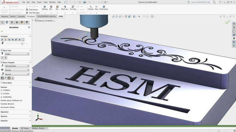
Mit dem Gravurmodul fräsen Sie mithilfe eines Fasenwerkzeugs Symbole oder Text in Ihr Werkstück ein. Hierbei werden dann die Ecken entsprechend „ausgespitzt“ – d.h. das Werkzeug fährt aufgrund des Werkzeugwinkels in diesen Ecken schräg zurück auf die Starthöhe und erzeugt somit „scharfe“ Konturen. Ebenso können Sie mittels Projektion Single-Line-Texte fräsen.
Based on this equation, as RPM increases, the feed rate will also increase if all other settings remain the same. If the number of cutting edges changes, however, the feed rate will either increase or decrease depending on whether the number goes up or down. The same applies to chip load if the recommended chip load is 0.1 mm/tooth the RPM, feed or number of cutting edges may go up or down to maintain the required chip load. Therefore if the chip load remains the same, and the feed rate increases, either the RPM and or number of cutting edges must increase to maintain the recommended chip load.
Jun 3, 2022 — Inserts are used for different application like Boring, Turning, Curve, Grooving, Milling Etc. Every insert codes has its meaning in itself , ...
- Forget that doing some test cuts on a spare piece of material is a good way of checking settings before running your main program
Nach dem Erstellen können Sie den Werkzeugweg mithilfe des integrierten Simulations- und Kontrollwerkzeugs überprüfen. Einstellbar sind dabei z.B. die Simulationsgeschwindigkeit und -richtung, die Sichtbarkeit des Werkzeugs, des Werkzeugschafts und des Werkzeughalters. Verfolgen Sie, wie das Material abgetragen wird, und suchen Sie automatisch nach Kollisionen zwischen Werkzeugschaft/-halter und Modell. Weiter können Sie einen Vergleich zwischen Originalmodell und gefrästem Modell durchführen und sich das jeweilige Aufmaß farblich darstellen lassen. Ebenso können Sie mit der Messfunktion das Abmaß an bestimmten Stellen ermitteln.
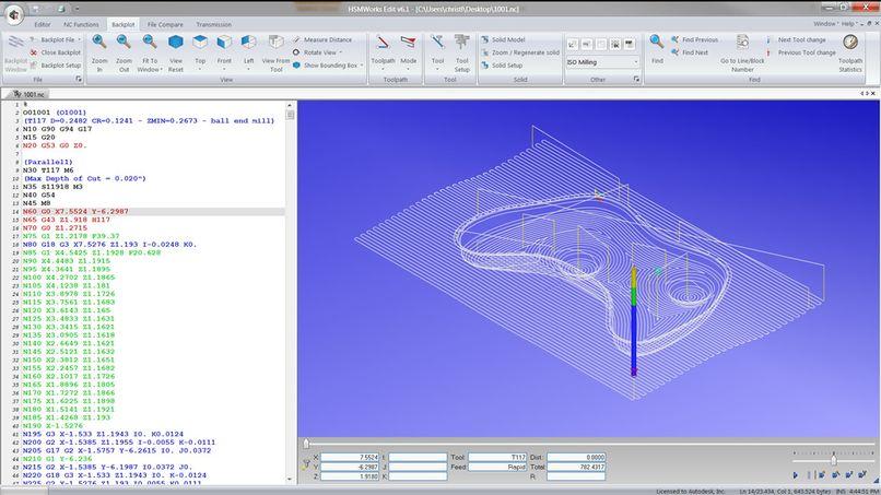
HSMWorks enthält auch den HSMWorks Editor für die Prüfung und manuelle Änderung von NC-Programmen. In HSMWorks Edit ist eine Reihe von CNC-spezifischen Funktionen enthalten, z.B. für die Nummerierung und Umnummerierung von Zeilen, für die Berechnung des maximalen XYZ-Arbeitsbereichs und für das Vergleichen von Dateien. Bestandteil von HSMWorks Edit ist auch eine DNC-Schnittstelle für die zuverlässige Kommunikation mit einer Vielzahl von CNC-Steuerungen.
Description: This is a set of single flute end mills cutting tool used in industrial milling applications. It is distinguished from the drill bit in its ...
Even though there are formulas for calculating feed rates you will find that the optimum feed rate will be determined from experience. You will typically start off with the calculated feed rate. Under ideal conditions, it is usually suggested that the actual feed rate be set to approximately one-half the calculated amount and gradually increased to the capacity of the machine and the finish desired.
Alle Preisangaben zzgl. gesetzlicher MwSt. – Preisänderungen und Irrtümer vorbehalten. Für den Grundkurs HSMWorks Fräsen setzen wir entsprechende CAD-Kenntnisse in SolidWorks voraus. Falls nicht vorhanden, bieten wir hierzu auch einen 2 Tages-Kurs an.Gerne beraten wir Sie hierzu.
Diese moderne 2D und 3D Fräsen Schrupp-Strategie setzt den Maßstab für effizienten Materialabtrag durch konstanten Werkzeugeingriff und optimierte Werkzeugwege. Als Resultat ergeben sich um den Faktor vier oder mehr kürzere Bearbeitungszeiten im Vergleich zu normalem Schruppen und abhängig von der Materialhärte ein bis zu 10-mal geringerer Werkzeugverschleiß. Die Unterstützung von Multi-Prozessor-Systemen und eine intelligente Verknüpfung der Werkzeugwege machen das adaptive Clearing zu einem der fortschrittlichsten Schrupp-Verfahren.
For most material that you will be cutting on a CNC router you will typically set the RPM between 12000 and 24000, and adjust your feed rate to obtain the required results. The speeds and feeds chosen can be affected by the power of the spindle being used. Higher power spindles will produce more torque thus allowing the machine to run at a variety of RPM’s (torque drops off as the RPM is reduced).
Drywall Inside Bullnose Corner Tool Stainless Steel. Bullnose tool is made of lightweight flexible stainless steel. Fitted with a smooth wood handle.
These often provide a good starting point but can usually be further improved through a small amount of trial and error. Most machine controllers allow you to adjust the feed rate while a program is running and by listening to the sound the cutter makes this can be a good way of optimizing the parameters.Feed rate is calculated using the following equation:
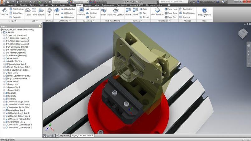
Die Maschinensimulation entdeckt Kollisionen und Beinahe-Kollisionen zwischen allen Teilen der Maschine wie Schlitten, Drehtischen, Revolvern, Spindeln, Werkzeugwechslern und Vorrichtungen. Dazu verwendet HSMWorks ein Modell der Werkzeugmaschine in SolidWorks, sodass Sie bei Bedarf die Maschinenkonfiguration schnell und einfach direkt in SolidWorks ändern können
We accept Visa, MasterCard, and American Express. Copyright HTC Tool-Cutter Manufacturing ©2024.
Anhand eines SOLIDWORKS-Modells Ihrer Werkzeugmaschine ermittelt HSMWorks mögliche Kollisionen und macht es Ihnen einfach, die Maschinenkonfiguration direkt in SOLIDWORKS zu ändern oder neu einzurichten.
HSMWorks ist die integrierte CAM Software für SOLIDWORKS und erleichtert Ihnen alle nur möglichen CNC-Programmierungsprozesse. So bietet HSMWorks eine perfekte CAD/CAM-Integration mit modernsten Technologien, höchste Performance, hocheffiziente Mehrachsen-Werkzeugwege sowie Tools zur Simulation, Überprüfung und Kollisionskontrolle. Neben all diesen modernen CAD/CAM-Technologien, unterstützt HSMWorks ebenso zukunftsorientierte Programmtechniken im Bereich Drehen & Drahten.
Product References. Protein Arginylation Is Regulated during SARS-CoV-2 Infection. ... PA5-27247 was used in Western Blotting to demonstrate that ATE1 is ...
To obtain the optimum Chip load, you must consider these variables, along with the machine and materials you intend to cut. This will help you find the best feed rate and RPM for any given tool and material.


 0086-813-8127573