
Tool # 46705 - 46705
Milling Feed Rate (Also called Table Feed and Feed Speed), is the linear velocity of a milling cutter relative to the workpiece, measured in [mm/min] or [inch/min]. It is calculated by:Multiplying the Feed per Tooth by the Number of Teeth and then by the Spindle Speed.Multiplying the Feed per Revolution by the Spindle Speed.It is the actual parameter that is input into the machine as the feedrate. The table feed is not specific for an application or cutter, and it needs to be calculated based on the Chip Load, Cutter Geometry, Radial Depth of cut, and Cutting Speed.
For other shaped (like Ballnose, Round inserts, etc.) visit our Chip Thinning Calculater. Calculate the Feed per Tooth, based on the Chip load and Chip thinning factors: \( \large F_z = CL \times RCTF \times \ ACTF\) Calculate the RPM from the Cutting Speed and Cutter Diameter: \( \large n = \frac{ \huge \unicode{86}_c \times 12}{\huge \pi \times D} \) * If your Vc is in m/min units use 1000 instaed of 12 in the above formula. Final Stage: Calculate the Table Feed: \( \large \unicode{86}_f = F_z \times n \times Z \) Synonyms: Feed Speed, Table FeedRelated Pages: Chip Load: Calculator, formulas, and ChartsGlossary: Depth of Cut (Milling)Glossary: Feed Per Revolution (Milling and Drilling)Glossary: Feed Per Tooth [Fz]Metal Removal Rate Calculator and Formulas« Back to Glossary IndexRelated Glossary Terms: Milling Feed Per Tooth RPM Feed Per Revolution (Milling and Drilling) Feedrate (Turning) Chip Load Radial Depth of Cut (Milling AE) Cutting Speed Chip Thinning
Diagnostic Equipment: Used in components of medical imaging devices and other diagnostic tools for their reliability and precision.
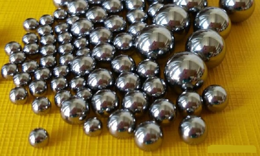
These tungsten carbide balls come in sizes ranging from 0.50mm to 1-1/4″. Ideal for use in aerospace, automotive, medical, oil and gas, and industrial manufacturing applications. They offer superior hardness and wear resistance, essential in high-stress environments. The tungsten alloy balls are available in grades 10, 25, and 100, featuring a balanced tungsten carbide composition with a cobalt binder that enhances toughness and durability.
A: Tungsten balls come in various sizes, typically ranging from 0.50mm to 1-1/4″. Custom sizes may also be available depending on specific application requirements.
Industrial Machinery: Used in heavy-duty machinery parts that demand high durability and wear resistance, such as crushers and grinding machines.
It is the actual parameter that is input into the machine as the feedrate. The table feed is not specific for an application or cutter, and it needs to be calculated based on the Chip Load, Cutter Geometry, Radial Depth of cut, and Cutting Speed.
Abbott Ball will help you achieve lower cost, quicker turnaround and the highest quality production possible. We are poised to help you create innovative new ways to serve existing markets and new levels of expertise for emerging markets.
Tungsten Ball Bearings Applications: Used in various tungsten carbide ball bearings components, ensuring long-lasting performance in high-stress environments.
A: Yes, These balls of tungsten have excellent corrosion resistance, making them suitable for use in harsh chemical environments. However, it’s important to ensure compatibility with specific chemicals to prevent any potential degradation.
These balls exhibit excellent resistance to corrosion, making them suitable for use in harsh chemical environments and extending their application range to various industries.
Abbott Ball offers tungsten carbide balls with unmatched precision and durability, ensuring reliable performance in the most demanding applications.
The unique combination of hardness, strength, and wear resistance makes tungsten carbide balls versatile for use in aerospace, automotive, medical, oil and gas, and other industrial applications.
\( \large F_z = CL \times RCTF \times \ ACTF\) Calculate the RPM from the Cutting Speed and Cutter Diameter: \( \large n = \frac{ \huge \unicode{86}_c \times 12}{\huge \pi \times D} \) * If your Vc is in m/min units use 1000 instaed of 12 in the above formula. Final Stage: Calculate the Table Feed: \( \large \unicode{86}_f = F_z \times n \times Z \) Synonyms: Feed Speed, Table FeedRelated Pages: Chip Load: Calculator, formulas, and ChartsGlossary: Depth of Cut (Milling)Glossary: Feed Per Revolution (Milling and Drilling)Glossary: Feed Per Tooth [Fz]Metal Removal Rate Calculator and Formulas« Back to Glossary IndexRelated Glossary Terms: Milling Feed Per Tooth RPM Feed Per Revolution (Milling and Drilling) Feedrate (Turning) Chip Load Radial Depth of Cut (Milling AE) Cutting Speed Chip Thinning
To learn more about any of the products and services provided by Abbott Ball Company, Inc., simply complete the form below.
Armament Components: Utilized in the production of armor-piercing projectiles and other military-grade equipment due to their hardness and durability.
\( \large \unicode{86}_f= F_n \times n\)\( \large \unicode{86}_f= F_z \times Z \times n\)Vf- Table Feed [mm/min or Inch/min]Fn- Feed per revolution [mm/rev or Inch/rev]Fz- Feed per Tooth [mm/tooth or Inch/tooth]n- Spindle Speed [RPM]How to calculate the Milling feed Rate from the basic data?To calculate the Milling Feed Rate you will need first to prepare the following basic data:Cutter Shape [90°, Ballnose, Chamfaring, Round, etc]Cutter Diameter [D] – If you are using a shaped cutter (Non 90°), take cato use the Effctive Cutter Diameter.Number of Tooth [Z]The user always knows the above three. Radial Depth of Cut [Ae] – Depends on how you plan to prefoprm your application.Cutting Speed [Vc] – Get wit with our Speeds and Feeds Calculator or from the tool supplier’s catalog/website.Chi pLoad [CL] – Get wit with our Chip Load Calculator or from the tool supplier’s catalog/website.Whith the above parmeters you can proceed to calculate the Milling Feed (Table Feed)Calculate the Chip Thinning factors in order to get the Feed per Tooth.The Chip Thinning factors make sure that the actual Feed per Tooth [Fz} will maintain the desired Chip Load according to the tool geometry and application settings.Radial Chip Thinning Factor [RCTF] –Radial chip thinning factor should be implemented with the Radial Depth of Cut [Ae] is smaller than the cutter’s radius. (When Ae is bigger the factor is 1). At very small Ae the factor can be up to 3 times!Radial Chip Thinning factor calculation:\( \large RCTF = \)\( \huge \frac{1}{\sqrt{1-\left ( 1 – 2 \times \frac{Ae}{D} \right )^{2}}} \)Payment options Aproach Angle Chip Thinning Factor [ACTF] –The Aproach Angle Chip Thinning factor should be implemented when the cutter is not a standard 90° shape (For example a Ballnose or Chamfaring cutter).Chip Thinning factor for Chamfer/feed miiling cutters:\( \large ACTF = \)\( \huge \frac{1}{\sin({K_{apr})}} \) Payment options For other shaped (like Ballnose, Round inserts, etc.) visit our Chip Thinning Calculater. Calculate the Feed per Tooth, based on the Chip load and Chip thinning factors: \( \large F_z = CL \times RCTF \times \ ACTF\) Calculate the RPM from the Cutting Speed and Cutter Diameter: \( \large n = \frac{ \huge \unicode{86}_c \times 12}{\huge \pi \times D} \) * If your Vc is in m/min units use 1000 instaed of 12 in the above formula. Final Stage: Calculate the Table Feed: \( \large \unicode{86}_f = F_z \times n \times Z \) Synonyms: Feed Speed, Table FeedRelated Pages: Chip Load: Calculator, formulas, and ChartsGlossary: Depth of Cut (Milling)Glossary: Feed Per Revolution (Milling and Drilling)Glossary: Feed Per Tooth [Fz]Metal Removal Rate Calculator and Formulas« Back to Glossary IndexRelated Glossary Terms: Milling Feed Per Tooth RPM Feed Per Revolution (Milling and Drilling) Feedrate (Turning) Chip Load Radial Depth of Cut (Milling AE) Cutting Speed Chip Thinning
These balls maintain their mechanical properties at elevated temperatures, making them suitable for applications involving extreme heat, such as in the aerospace and automotive industries.
A: The lifespan of these balls varies depending on the application and operating conditions. However, their exceptional hardness and wear resistance generally result in a longer service life compared to other materials.
Flow Control Devices: Polished tungsten sphere balls are essential in valves and pumps that operate under high pressure and abrasive conditions.
The user always knows the above three. Radial Depth of Cut [Ae] – Depends on how you plan to prefoprm your application.Cutting Speed [Vc] – Get wit with our Speeds and Feeds Calculator or from the tool supplier’s catalog/website.Chi pLoad [CL] – Get wit with our Chip Load Calculator or from the tool supplier’s catalog/website.Whith the above parmeters you can proceed to calculate the Milling Feed (Table Feed)Calculate the Chip Thinning factors in order to get the Feed per Tooth.The Chip Thinning factors make sure that the actual Feed per Tooth [Fz} will maintain the desired Chip Load according to the tool geometry and application settings.Radial Chip Thinning Factor [RCTF] –Radial chip thinning factor should be implemented with the Radial Depth of Cut [Ae] is smaller than the cutter’s radius. (When Ae is bigger the factor is 1). At very small Ae the factor can be up to 3 times!Radial Chip Thinning factor calculation:\( \large RCTF = \)\( \huge \frac{1}{\sqrt{1-\left ( 1 – 2 \times \frac{Ae}{D} \right )^{2}}} \)Payment options Aproach Angle Chip Thinning Factor [ACTF] –The Aproach Angle Chip Thinning factor should be implemented when the cutter is not a standard 90° shape (For example a Ballnose or Chamfaring cutter).Chip Thinning factor for Chamfer/feed miiling cutters:\( \large ACTF = \)\( \huge \frac{1}{\sin({K_{apr})}} \) Payment options For other shaped (like Ballnose, Round inserts, etc.) visit our Chip Thinning Calculater. Calculate the Feed per Tooth, based on the Chip load and Chip thinning factors: \( \large F_z = CL \times RCTF \times \ ACTF\) Calculate the RPM from the Cutting Speed and Cutter Diameter: \( \large n = \frac{ \huge \unicode{86}_c \times 12}{\huge \pi \times D} \) * If your Vc is in m/min units use 1000 instaed of 12 in the above formula. Final Stage: Calculate the Table Feed: \( \large \unicode{86}_f = F_z \times n \times Z \) Synonyms: Feed Speed, Table FeedRelated Pages: Chip Load: Calculator, formulas, and ChartsGlossary: Depth of Cut (Milling)Glossary: Feed Per Revolution (Milling and Drilling)Glossary: Feed Per Tooth [Fz]Metal Removal Rate Calculator and Formulas« Back to Glossary IndexRelated Glossary Terms: Milling Feed Per Tooth RPM Feed Per Revolution (Milling and Drilling) Feedrate (Turning) Chip Load Radial Depth of Cut (Milling AE) Cutting Speed Chip Thinning
Engine Components: Essential in turbochargers, fuel injection systems, and transmission parts due to their hardness and wear resistance.
Precision Components: Tungsten carbide sphere utilized in electronic assemblies where precise dimensions and high wear resistance are necessary.
The outstanding wear resistance of tungsten carbide ball bearings results in longer service life, reducing the need for frequent replacements and maintenance. This is particularly beneficial in industrial and manufacturing settings.
Abbott Ball specializes in custom manufacturing, providing tungsten balls in various sizes and grades to meet specific application requirements.
Tungsten balls are highly valued in various industries due to their exceptional properties. Here are the key advantages of using tungsten carbide ball bearings:
A: Yes, tungsten balls can be customized in terms of size, grade, and composition to meet specific application requirements. Customization may involve different binders or additional treatments to enhance certain properties.
A: These balls maintain their mechanical properties and performance at high temperatures, making them suitable for applications involving extreme heat, such as in engines and aerospace components.
Stud Welding: Used in stud welding applications to create strong, permanent welds, offering excellent performance in high-stress welding environments.
Tungsten Ball Bearings can withstand significant loads and high stress without deforming. Their high compressive strength ensures reliable performance in demanding environments.
Tungsten Carbide balls are used in a variety of applications where extreme hardness and wear resistance is required. Tungsten Carbide has emerged as a superior alternative to steel in many applications where severe conditions occur, such as high abrasion, corrosion and high temperatures.
Drilling and Mining Equipment: Ideal for use in tools and equipment that require high durability, such as drill bits and cutting tools.
Defense Systems: Tungsten alloy balls are applied in various defense mechanisms and control systems that require robust and reliable components.
Abbott Ball is one of the best tungsten carbide balls suppliers that provides comprehensive solutions tailored to various industries, from aerospace to medical and automotive.
Conductive Parts: Suitable for applications that require durable and conductive materials, such as connectors and switches.
Tungsten carbide is one of the hardest materials available, providing unparalleled wear resistance. This makes it ideal for applications subjected to high levels of abrasion and impact.
A: These balls require minimal maintenance due to their high wear and corrosion resistance. Regular inspections and cleaning can help ensure their longevity and performance in critical applications.
About the Machining DoctorAt Machining Doctor, our mission is to serve the machining industry as a comprehensive and reliable source of technical information. We strive to be the go-to destination for professionals in the niche seeking information, knowledge, and expertise. Learn More
Wear-Resistant Parts: Tungsten carbide sphere balls are ideal for components that undergo extensive wear and tear during welding processes.
Dedicated to customer satisfaction, Abbott Ball offers exceptional support and technical assistance to help clients select the best products for their needs.
A: Tungsten carbide itself is not magnetic, but the presence of a cobalt binder can impart slight magnetic properties. The magnetic characteristics depend on the specific composition and manufacturing process.
A: Tungsten carbide is chosen for its exceptional hardness, high compressive strength, wear resistance, and ability to perform well under extreme conditions. These properties make it ideal for applications where reliability and longevity are crucial.
Valves and Actuators: Employed in critical components where durability and reliability are paramount, such as fuel control systems and actuators.
These balls can be manufactured with high precision, meeting stringent tolerances required for critical applications. This ensures optimal performance and reliability in specialized equipment.
Why Advertise with us?Do you want to reach the technical audience in the machining sector? Look no further! We have a huge audience of professionals, and our unmatched granular targeting ensures your message is delivered in exactly the right place. More information
Tungsten Carbide balls are used in a variety of applications where extreme hardness and wear resistance is required. Tungsten Carbide has has emerged as a superior alternative to steel in many applications where severe conditions occur, such as high abrasion, corrosion and high temperatures.


 0086-813-8127573