
Trirock 5-Pack Black M-LOK Picatinny Rail Sections kit fits ... - picanny
The microstructure is composed of a carbon-depleted primary phase and a carbon-rich-secondary phase4. Bainite arises from a mixture of shear mechanism without diffusion and a diffusion-controlled formation, but it remains unsettled which mechanism is dominant5. The ratio of diffusion-less and diffusion-controlled parts causes differences in the sub-structures. This led several researchers to introduce different classification schemes. The most prominent classes are lower and upper bainite6. Depending on temperature, upper bainite typically transforms mostly diffusion-controlled at higher temperatures. Lower bainite transforms mainly diffusion-less at lower temperatures7. These classes can be visually identified by carbide formation within the secondary phase (upper bainite) or in the primary phase (lower bainite)8. Varieties increased with advances in the steel production (higher precision in the alloying of steels) and with precisely controlled heat treatments. Besides carbides, Zajac et al.9 incorporates incomplete transformation products in the secondary phase and classifies these microstructures as “degenerate bainite”. Martensite-austenite (MA) islands are an example of degenerate constituents. While MA islands in lower and upper bainite occur as elongated up to film-like structures (high length:width ratio), a slow continuous cooling can lead to the formation of granular bainite containing block-type (length:width ≈1) MA islands10. Further classifications are described in11. Those classifications can be used to predict the mechanical behavior, where the existence of coarse MA islands is an indicator for a decrease of impact energy12,13. Unfortunately, prior research lacks quantitative measurements with meaningful numbers of MA islands. Often only the average size was used to interpret this sub-structure in bainite. Given the manifold morphologies of MA, the average size appears insufficient to describe the correlation between microstructure and mechanical properties.
Following the polygon annotation phase, the quality of polygon annotations was controlled by two activities. First, we automatically checked if the polygons are valid. The validity of a polygon means that the polygon rings are closed, edges do not intersect with each other, and the edges do not overlap. Secondly, the outcome polygons were individually displayed on base images and carefully visually inspected by the curators.
The number of POIs resulted by the agreement of all three annotators was 2.913, while the number of POIs agreed by two or three annotators was 8.909. At this step, we removed 63 images from the dataset because there were no agreed-upon POIs marked on them.
Each entry in the expert segmentation table represents a polygon that marks the boundary around an MA structure. The POIs that lead to the drawing of a particular polygon annotation is also provided within the data table. Polygons are defined by a series of consecutive point tuples such as the following example. [(720, 288), (725, 294), (731, 300), (737, 30), …]
“You need some sort of support to keep the drill stable when you break through into the cross-hole,” Zaitoon said. “With an insert drill, there’s no margin behind the cutting edge to stabilize it like there is with other drills.”
The image data set includes 2.580 TIFF files and their PNG equivalents for displaying on web browsers for annotation purposes35. TIFF files are the original outputs of the SEM and PNG equivalents are created to be displayed on web browsers for annotation purposes. Note that only 1.705 of the images have polygon annotations associated with them. The remaining image files are excluded due to suboptimal image quality or there are no agreed-upon MA-islands indicated on them. These images are provided in a separate folder.
Habben made a final point, one that machinists often overlook. TIR, or total indicator runout, should be less than 0.001 " and preferably better than 0.0005 "—a critical characteristic for improved tool life and hole accuracy. That might sound like a tall order to many shops, but Habben argued it is easily achieved with high-quality hydraulic or shrink-fit toolholders.
No edge prep in the world, however, will help without a good drill. The cutting forces generated on breakthrough when cross-hole drilling can be tremendous, and deflection becomes a real problem. Al Zaitoon, sales and marketing manager for YG-1 Tool Co., Vernon Hills, Ill., explained that indexable-insert drills, or insert drills, a staple in most machine shops, are not the answer for cross-hole drilling.
The martensite fraction in these islands cause a local hardness gradient and act therefore as brittle spots prone to produce microcracks29. Large MA islands commonly inherit large martensitic areas, but in the case of elongated islands, carbon can diffuse and stabilize more austenite in the MA islands during cooling.
Steel microstructurediagram
Some additional items in the cross-hole drilling first-aid kit are advanced coatings and lots of coolant because the process can generate a lot of heat. “Coatings help, because many times in cross-hole drilling you’re running at a reduced feed rate, which means poor chip formation,” Habben said. He noted Sumitomo offers a polished, TiAlCr coating just a few microns thick. “It uses nano-coating technology, meaning the coating is applied in extremely thin layers. This makes it very lubricious and significantly less expensive than a diamond coating, while offering comparable tool life.”
Mildsteel microstructure
This section collects any data citations, data availability statements, or supplementary materials included in this article.
The POI lists are stored as coordinate-tuples. An example list that contains four points is as the following. [(616, 319), (820, 286), (986, 522), (880, 521)]
Studying steel microstructures yields important insights regarding its mechanical characteristics. Within steel, microstructures transform based on a multitude of factors including chemical composition, transformation temperatures, and cooling rates. Martensite-austenite (MA) islands in bainitic steel appear as blocky structures with abstract shapes that are difficult to identify and differentiate from other types of microstructures. In this regard, material science may benefit from machine learning models that are able to automatically and accurately detect these structures. However, the training process of the state-of-the-art machine learning models requires a large amount of high-quality data. In this dataset, we provide 1.705 scanning electron microscopy images along with a set of 8.909 expert-annotated polygons to describe the geometry of the MA islands that appear on the images. We envision that this dataset will be useful for material scientists to explore the relationship between the morphology of bainitic steel and mechanical characteristics. Moreover, computer vision researchers and practitioners may use this data for training state-of-the-art object segmentation models for abstract geometries such as MA islands.
Stainlesssteel microstructure
We envision two usage scenarios for this dataset. Firstly, material scientists can use the data to explore the relationship between a variety of characteristics of steel with the MA islands that exist in them. Secondly, machine learning researchers and practitioners can use the annotated shapes as high-quality training data to train state-of-the-art object segmentation models37. The methods to visualize the polygons and points on the images are also provided within the code to allow researchers to visually inspect the geometries on the detected MA islands.
On the other end of the spectrum are P-2 tool steel injection molds for complex medical devices, with more holes than a block of Swiss cheese and tolerances that make even veteran machinists weep.
In total, 10 steel samples with different chemical and heat treatments were investigated. The characteristics of the steel samples are associated with each image and provided in the metadata table. These characteristics include a label that indicates the chemical composition of the samples, phase transformation temperature, the direction of the photography axis, the distance of the sample to the edge, magnification level, and the tilt angle. The details of these characteristics are provided in the data records section. Prior to the annotation step, the experts were trained to identify MA islands based on a thorough microstructural characterization of bainite microstructures from preselected samples31.
In total, 2.580 images were annotated separately and redundantly by three domain experts. At this step, the annotation task consisted of marking a point that is inside the blocky MA region. The annotators were instructed to provide one and only one POI marker per structure. Therefore, we make the assumption that every marker put by a particular annotator belongs to exactly one MA structure that is visible on the image. However, markers that are placed by different annotators may indicate the same MA structure which may mean that the experts agree on the existence of a particular structure. Images were displayed in 1024 × 768 resolution, and the coordinates of annotated POIs were recorded in that resolution scale. For completeness, the annotators marked all MA structures that they could identify on the images.
The automated identification of microstructures in steel poses a specifically intriguing challenge in machine learning. Steel micro-imagery consists of very complex images having a significantly large amount of abstract patterns appearing on the image in comparison to the application of object detection or segmentation in other problem domains such as pedestrian and vehicle detection21,22. Therefore, the expected benefit of transfer learning (i.e., applying the knowledge gained while training to solve a particular problem to a different yet similar problem) is limited.
Prior to the SEM analysis, samples were metallographically prepared by grinding and polishing with a surface finish of 1 µm. Nital etchant (3% nitric acid) was used to reveal the bainitic microstructure for SEM. The austenite fraction inside MA islands is mechanically unstable. Thus, mechanical loading (grinding and polishing) during sample preparation can cause a transformation of meta-stable austenite. This effect needs be minimized before interpreting microstructural data to account only for the material-related occurrences. Prolonged polishing with oxide polishing suspensions or (electrolytic) etching provides a deformation-free surface, so austenite stays intact inside the MA islands30. Only secondary electron detectors were used that yield topographic information to take micrographs of local spots covering an area of nearly 650 µm2. In case of the studied MA structures, the islands show a topographic effect in the SEM image. This effect originates from the etching response and manifests in a brighter appearance from the outer rim to the centre of the island. For larger islands, etching even reveals refined lath structures in the centre of the islands. The complexity of the given task lies in differentiating the MA islands from occasional carbides (bright points) and film-type austenite. These film-type structures occur as elongated and bright films with a thickness in the range of nanometer. The images were acquired in a Zeiss Sigma field emission gun SEM with secondary electron and Inlens detectors by Oxford. In this procedure, SmartSEM software was used. The SEM was operated at 15 kV with a working distance below 10 mm and with 60 µm aperture.
Even for the experts, detecting bainite structures is a challenging task. As an attempt to decrease the number of falsely identified bainite structures, we used majority decision which is a commonly applied quality assurance method in information retrieval32. The idea behind the majority decision is that if multiple annotators agree on one annotation separately, the likelihood of an error is decreased. For this spatial annotation task, we used Euclidean Distance measurement along with a threshold to calculate agreement. Thus, if the distance between the markers placed by different annotators is smaller than the threshold, the markers are assumed to indicate the same point of interest. This threshold value differs based on the characteristics of the images in terms of object frequency and distribution. The experts have decided to set the threshold as 0.4 micrometers (~30 pixels under 4000x magnification level), by manually analyzing the POIs marked. An example image with individual annotations and agreed-upon POIs can be seen in Fig. 4. In order to predict the agreement on multiple points, we made a pairwise Euclidean Distance measurement of all POIs marked by the annotators. If two or three POIs (each marked by a different annotator) were closer to each other in comparison to the threshold value (0.4 micrometer), we accepted the centroid of those POIs as the agreed POIs.
Segments that are drawn by an expert. The red dots mark the agreed-upon POIs that were collected in the POI annotation step.
In this section, we describe our method for generating the data, and measuring and calculating features. Fig. 1 represents the steps of our research process that includes data collection, annotation, feature calculation, and evaluation.
Hans Liechti of Mikron Tools sees things differently. While he acknowledges the complexities of cross-hole drilling, Liechti said CAM software should have no problem calculating the proper toolpath. “It’s not as much of a big deal as it once was.”
The evaluation table consists of three additional features on top of the baseline contour detection model; area of the expert-annotated polygons, area of the automatically detected contours, and the Intersection-over-Union (IOU) as a measure of segmentation accuracy.
Habben added that for holes below ½ " in diameter, “solid carbide is the only way to go.” However, he warned, anything much larger than this and you could be talking serious cash, whereas a replaceable-tip drill is about half the cost and as accurate. Habben said: “A lot of cross-holes are deep, maybe 12 to 20 times diameter. With hole sizes running anywhere from 1⁄8" to 1 " or more, solid-carbide tools this long can get expensive, especially for large holes. You can easily spend $500 to $800 per drill.”
Distance is the distance to the edge of the sample cross-section in either horizontal or vertical direction. The maximum distance in horizontal direction can be 24 mm and in vertical direction 13 mm. These distances are a result of the deformation of the sample by compression.
Replaceable-tip drills have basically the same geometry as solid-carbide drills, with two effective cutting edges in a one-piece design. The head is secured with screws against a ground serration. This offers high locational accuracy as well as strength in the drive mechanism, according to Habben.
Two challenges in machine learning that are relevant to the MA detection task are object detection (i.e., detecting the existence of the object and specifying the location of the object on the image) and object segmentation (i.e., drawing the boundaries around the object that separates it from the rest of the image). Object detection applications have seen an improvement in performance in the last years, thanks to the advent of new deep learning methodologies and architectures. Deep learning allowed researchers to move from a sliding window approach to generate bounding boxes to new strategies for specifying regions of interest. Several examples are Regions with Convolutional Neural Network features (RCNN)17 and You Only Look Once (YOLO)18, which generate regions with respect to a fixed grid by regressing the position of the bounding boxes. Similar to YOLO, Single Shot Multi-Box Detector (SSD) produces the prediction of the bounding boxes by means of a single forward pass on top of a convolutional neural network network19,20. Although, the architectural developments show promise, training object detection and segmentation models require a significant amount of high-quality annotated data, and expert-annotated image sets are rare to come across.
Magnification is the magnification level while taking images with the electron microscope. All images in this dataset were recorded under 4000x magnification.
After having the list of agreed POI coordinates, the expert annotators performed the segmentation task using the annotation software. Each of the 8.909 agreed POIs were displayed on the base image and the annotator was asked to draw a bounding polygon around the blocky structure. In order to avoid distraction, the expert was provided with one POI at a time and drew only one polygon to segment a single bainite structure at a time. After the completion of each segmentation task, the annotation software displayed a randomly chosen POI from the agreed-upon POI list. The polygons were represented as an ordered list of point tuples with x and y coordinates that resulted from the mouse clicks of the expert annotators. An example visualization of such segments is shown in Fig. 5.
In cases where this doesn’t quite cut the mustard, Brown recommends a special, where the body of the drill has guides to help stabilize it through the interruption.
All codes that were used in the preparation and the analysis of this dataset are made available along with the dataset and in our code repository38. Codes are written in Python language. Specifically, two Jupyter Notebooks were provided; one that contains the code that describes the data tables and calculates the morphological feature, and another for contour detection and evaluation of the segmentation model. The code includes all custom methods, references to common libraries, and a full set of stepwise instructions to replicate the calculations in this study.
Conditioning of the cutting edge, such as a honing or chamfering, to make it stronger and less susceptible to chipping. A chamfer is a bevel on the tool’s cutting edge; the angle is measured from the cutting face downward and generally varies from 25° to 45°. Honing is the process of rounding or blunting the cutting edge with abrasives, either manually or mechanically.
Direction indicates the direction on which axis the photograph has been taken. It can be ‘Horizontal’ for left-to-right and ‘Vertical’ for top-to-bottom.
Cementitemicrostructure
Kip Hanson is a contributing editor for Cutting Tool Engineering magazine. Contact him by phone at (520) 548-7328 or via e-mail at kip@kahmco.net.
Despite the competitive nature of cutting tool manufacturers, there’s a lot of consensus on cross-hole drilling recommendations, and most companies agree with the following advice:
Drilling cross-holes in some parts is no big deal. These are often simple parts, such as aluminum valve bodies, where the holes aren’t too deep and meet on-center, and the customer can live with a small burr at the intersection.
point_shapely: The Shapely representation of the point. This point resides within the polygon of the annotated MA island.
IOU: The area of intersection of the expert-annotated polygon and the automatically detected contour divided by the area of the union of them. This is a measure of segmentation accuracy.
That’s music to anyone’s ears. J.W. Done guarantees its product, whether it’s used to replace traditional manual deburring processes or in a CNC machine tool. “People ask us why we don’t have any product returns,” Kapgan said. “I tell them it’s because we don’t give a return address.”
Type describes the chemical composition of the steel. The specifics of the composition are not included in this dataset. Type property is only provided as a classification feature to indicate compositionally different classes.
Publisher’s note Springer Nature remains neutral with regard to jurisdictional claims in published maps and institutional affiliations.
Official websites use .gov A .gov website belongs to an official government organization in the United States.
Matt Sippel, senior product application engineer at Melin Tool Co., Cleveland, agreed: “The one big thing we’ve been doing for cross-hole drilling is putting a special geometry on our coolant-fed drills. The tip tends to be a little bit flatter, say, around 140°, with a slight chamfer on the outside edge, and sometimes an edge prep. This is an old trick in the aerospace industry. It tends to protect the corner of the drill as you break through into the intersecting hole.”
Like his competitors, Brown said edge preparation is key. “We grind a chamfer, what we call an SK2 corner clip, on the outer margin of the drill. This helps stabilize the tool while improving tool life and reducing burr formation. From a cross-hole standpoint, the secret is in the stability of the tool.”
All codes that were used in the preparation and the analysis of this dataset are made available along with the dataset and in our code repository38. Codes are written in Python language. Specifically, two Jupyter Notebooks were provided; one that contains the code that describes the data tables and calculates the morphological feature, and another for contour detection and evaluation of the segmentation model. The code includes all custom methods, references to common libraries, and a full set of stepwise instructions to replicate the calculations in this study.
Steel microstructureanalysis
The steps of the data generation process. The images of various steel samples were acquired via a scanning electron microscope. The MA islands that appear on these images were annotated redundantly by multiple experts as points-of-interest (POI). The set of POIs was refined into a smaller set based on the agreement of the experts using the spatial proximity of the individual annotations. Subsequently, the experts drew polygons on the boundary of the MA islands that were previously marked by the majority of experts. The agreed-upon POIs were also used to guide the automated contour detection around the MA islands. The generated polygons were benchmarked against the expert-annotated polygons. Finally, the morphological characteristics of expert annotated polygons were calculated.
Stringy portions of material formed on workpiece edges during machining. Often sharp. Can be removed with hand files, abrasive wheels or belts, wire wheels, abrasive-fiber brushes, waterjet equipment or other methods.
Despite an unorthodox name, the Crazy Drill has all the requirements needed when it comes to cross-hole drilling, with a 140° drill tip, double-margin flutes and a coolant-fed, solid-carbide body. “You can be quite aggressive with these tools, up to five times the typical feed rate, then slow down as you break through into the cross-hole.”
Like his peers, Alex suggested reducing the feed by at least half when breaking into the cross-hole. “Once you’re in the clear, you can go faster, at least until the far side of the cross-hole. That’s where I recommend really dropping the feed rate, maybe a thou or two per rev, so the drill doesn’t walk. Finally, once the point angle is fully engaged, you should immediately increase the feed rate again so you don’t have chip control issues.”
Material scientists have been working on the identification, explanation, and replication of those structures. Understanding the mechanisms that lead to the formation of those specific morphologies is necessary to describe their impact on the mechanical properties. However, different sizes, shapes, and structures in bainite cause, until now, a manifold interpretation based on a subjective feature description by the expert who currently examines the microscopic images manually. Correlative metallography is a common approach to retrieve complementary knowledge about sub-structures14,15. Correlative means to couple different experiments to gain morphological, crystallographic, or chemical data of the same spatial region in the sample. Otherwise, some of the microstructural information remains hidden16. Thus, the characterization of bainite microstructures on microscopy images poses a challenge, and detecting a clear correlation between microstructure and mechanical properties is extremely difficult. To improve reliability and reproducibility, recent developments in machine learning provide a promising approach to tackle the challenge of microstructure description by computer vision.
POI annotations table shows the entire set of annotations provided by all three experts. Each entry consists of the image name and an X, Y coordinate tuple that represents the offset coordinates of the point that was marked to indicate an MA structure by one of the experts. This table also includes the coordinates of MA structures that were agreed by either two or three experts.
Subsequently, we compared the outcome of the baseline contour detection method against the expert-annotated polygons. The baseline method yielded 0,35 IOU. This may suggest that the change in color and intensity are a part of the decision taken by the experts when drawing the boundaries of MA islands. Even though contour detection may not replace a machine learning segmentation model, it has the potential to ease the polygon annotation task and improve the quality of expert-annotations. Further research is required to improve the annotation procedure as well as to train segmentation models that can detect MA island boundaries accurately. To that end, this dataset comprises a rich source for training such machine learning models.
And there’s no argument on feeds and speeds. “Until you get to the cross-hole, you’re going to run the recommended feeds and speeds,” Brown said. “If it’s a really deep hole, you have to go a bit lighter. As a rule, we tell people to reduce the feed rate when cross-hole drilling. The problem is that you give up good chip formation when you do that, but you help ease the transition into the cross-hole. And once you engage fully on the other side of the hole, you can go back to normal.”
According to Dan Habben, applications engineer at Sumitomo Electric Carbide Inc., Mt. Prospect, Ill., cross-holes are always a problem child. “Probably the best tip I can give is this: don’t do it!” laughed Habben, who works with automotive suppliers and sees cross-holes in everything from transmission housings to hydraulic valves for diesel engines. “Our customers cut a lot of die-cast aluminum and gray cast iron, and one of the main problems we see, especially with aluminum, is burrs. In hydraulic systems, it’s important to get a clean hole. Any chips or hanging chads left in the workpiece might pass into the hydraulics, damaging a valve or pump.”
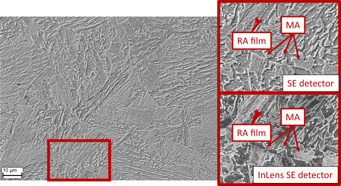
In the literature on bainitic microstructures, the characterization appears often ambiguous9,23–26. Nevertheless, no widely accepted quantitative characterization is available on steels containing bainite in the microstructure. This makes it difficult to draw conclusions from microscopic constituents to the macroscopic mechanical properties. Bainite consists of a carbon-depleted primary phase and a carbon-rich secondary phase with variations of morphologies depending on heat treatment and alloying elements7. The secondary phase can form so-called MA islands27. The MA structure becomes critical if carbon from adjacent phases has not enough time during cooling to penetrate the entire island. The resulting carbon depletion causes instability in the centre of the island resulting in fresh martensite transformation, while the outer rim remains only partly austenitic28. Fig. 2 shows an example of a bainitic microstructure with MA islands originated from two different microscope detectors. MA constituents occur in different shapes with highly elongated or rather round shaped structures. The indicated MA islands and the retained austenite films show both a topographic effect in the image causing sometimes difficulties to separate elongated MA from austenite films.
All kidding aside, the product works through a patented mechanism utilizing a flexible shaft together with a polished disk that acts like a cam follower against the hole wall, allowing the Orbitool to cleanly and effectively remove cross-hole burrs.
Also, examine the drilling sequence. “A lot of valve bodies use a porting tool for the valve seat, then a small cross-hole for the hydraulics, which is usually off-center. Correct processing of the part would be critical in this situation,” Habben said. “For example, the small-diameter holes for the hydraulics you would want to do first, and then go in with the porting tool after, because the larger tool is generally shorter and can handle the deflection better.”
Example visualization of POIs marked by the expert annotators. Red, green, and blue colored points are the POIs provided by annotators. Yellow points mark a POI that was agreed by two annotators. Purple colored points denote the agreement of three annotators.
An aggressive cutting head (top) is rigidly clamped to a through-coolant drill shank on Sumitomo’s SMD-style replaceable-tip drill.

Liechti is manager of the cutting tool division at Mikron Corp. Monroe, Monroe, Conn., which specializes in tools smaller than 6mm in diameter. This means a lot of solid-carbide, coolant-fed drills as well as custom step tools, reamers and porting tools.
SEM micrographs of a bainitic microstructure taken by two different detectors. The marked MA islands are composed of martensite in the center and austenite located at the outer rim causing a topography effect29. In contrast, retained austenite films reveal another topography effect in this type of microstructure.
Grooves and spaces in the body of a tool that permit chip removal from, and cutting-fluid application to, the point of cut.
Available in two major types: tungsten high-speed steels (designated by letter T having tungsten as the principal alloying element) and molybdenum high-speed steels (designated by letter M having molybdenum as the principal alloying element). The type T high-speed steels containing cobalt have higher wear resistance and greater red (hot) hardness, withstanding cutting temperature up to 1,100º F (590º C). The type T steels are used to fabricate metalcutting tools (milling cutters, drills, reamers and taps), woodworking tools, various types of punches and dies, ball and roller bearings. The type M steels are used for cutting tools and various types of dies.
aspect_ratio: The height of the bounding box of the polygon divided by the width of the bounding box of the polygon. This is an indicator of the shape of an MA island that is represented by the polygon.
Electron backscatter diffraction (EBSD) is a powerful instrument to gather morphological (grain size, area, and shape) and crystallographic (misorientation and texture) data of the microstructure. Together with atom probe tomography (APT), EBSD maps can be overlapped with element mappings to identify chemical gradients in MA constituents28. Unfortunately, EBSD is a time expensive method which requires also additional time for postprocessing. Therefore, EBSD (or APT) is not suitable for an analysis on larger surface areas or on a larger set of samples. For this reason, SEM images were chosen to generate efficiently a high quantity of image data suitable to be used as training input for computer vision models.
The amount of edge break is controlled by the preload on the tool together with simple programming techniques, providing anything from a sharp, burr-free edge to a large radius. “It’s just like milling a thread,” Kroll said. “We tell the tool the diameter of the hole and how deep to go. Orbitool takes care of the rest.”
Steel microstructuretypes
Fluid that reduces temperature buildup at the tool/workpiece interface during machining. Normally takes the form of a liquid such as soluble or chemical mixtures (semisynthetic, synthetic) but can be pressurized air or other gas. Because of water’s ability to absorb great quantities of heat, it is widely used as a coolant and vehicle for various cutting compounds, with the water-to-compound ratio varying with the machining task. See cutting fluid; semisynthetic cutting fluid; soluble-oil cutting fluid; synthetic cutting fluid.
Making the hole is sometimes the easiest part of cross-hole drilling. “We have customers that once took 10 hours to deburr hydraulic manifolds filled with dozens of holes,” said Stan Kroll, sales manager at J.W. Done Corp., Hayward, Calif. “And with one slip of the blade, the part was scrapped.”
Ferritemicrostructure
Milling cutter held by its shank that cuts on its periphery and, if so configured, on its free end. Takes a variety of shapes (single- and double-end, roughing, ballnose and cup-end) and sizes (stub, medium, long and extra-long). Also comes with differing numbers of flutes.
D.I.: Research lead, data curation, programming, writing and editing the manuscript. M.A.: Image data acquisition, data curation, writing and editing the dataset descriptor. J.G.: Data analysis, programming. G.P.: Data curation, reviewing and editing the manuscript. U.K.: Reviewing and editing the manuscript. S.W.: Reviewing and editing the manuscript. S.B.: Supervising the research, reviewing and editing the manuscript.
Kroll and J.W. Done President Michael Kapgan will tell you the Orbitool deburring device eliminates the craft factor of manual deburring. “You can literally do it with your eyes closed,” Kapgan said. “It greatly simplifies the manual deburring process. You just run it in and out of the hole, like you’re playing a violin.”
Included angle at the point of a twist drill or similar tool; for general-purpose tools, the point angle is typically 118°.
MA islands appear as abstract geometries and complex structures on microscopy images. This makes it difficult even for expert material scientists to identify these structures correctly, completely, and consistently. To ensure the accurate annotation of MA structures, we used a redundancy-based quality assurance approach, in which we selected the annotations based on the majority decision of multiple experts32. Out of 14.982, 9.670, and 9.785 individual annotations, we were able to identify 8.909 MA islands that were separately annotated by at least two experts, and 2.913 that were agreed-upon by three experts.
Open Access This article is licensed under a Creative Commons Attribution 4.0 International License, which permits use, sharing, adaptation, distribution and reproduction in any medium or format, as long as you give appropriate credit to the original author(s) and the source, provide a link to the Creative Commons license, and indicate if changes were made. The images or other third party material in this article are included in the article’s Creative Commons license, unless indicated otherwise in a credit line to the material. If material is not included in the article’s Creative Commons license and your intended use is not permitted by statutory regulation or exceeds the permitted use, you will need to obtain permission directly from the copyright holder. To view a copy of this license, visit http://creativecommons.org/licenses/by/4.0/.
Main body of a tool; the portion of a drill or similar end-held tool that fits into a collet, chuck or similar mounting device.
With this dataset descriptor, we contribute to both materials science and machine learning fields by providing (a) an image collection of steel microscopy on which blocky-type morphologies in bainite microstructures that are annotated by experts, (b) metadata regarding the morphology of these structures. Materials scientists may use the dataset to conduct bainite-related research, and machine learning practitioners may utilize the data to train and test object detection and segmentation models.
Habben said this is just part of the story, though. “As the drill tip breaks through into the intersecting hole, a rule of thumb would be to decrease the feed rate by about 50 percent. This helps minimize the number of burrs and also to reduce deflection, especially in an off-center situation.”
Lastly, we used contour detection to segment the already-detected microstructures. More specifically, the contouring procedure uses POIs to automate the consecutive step, which is to draw the boundaries of the MA islands that contain the POIs indicated by experts. The contouring procedure detects the boundaries based on stark changes in color and intensity. Therefore, it produces polygons that are much more complex and detailed than expert-annotated polygons. The purpose of applying the contouring procedure in our study is threefold. First, we aimed at seeing whether there is a pattern that could be captured to train models. We assume that the change of color and intensity comprises useful information regarding the boundaries of MA islands. The comparison of contouring and expert-annotated polygons allows us to evaluate the importance of color and intensity changes in detecting boundaries of MA islands. Second, we aimed at evaluating contouring as a supporting tool for the polygon annotation task. Due to the complexity and abstractness of the MA islands -and potentially many other microstructures that appear in steel-, contour detection methods can assist the annotator by fine-tuning the curvature of the polygon boundary that is indicated by POIs placed by the annotator. An example of a similar usage is the magic wand tool that is available in many image processing software products. Finally, contour detection provides a baseline model for segmentation. Therefore, any machine learning model trained for the segmentation of MA islands must overperform the baseline model in terms of accuracy.
Zaitoon painted this picture of a typical cross-hole. “Say you’re using a ½ " solid-carbide drill to go into a 3⁄8" cross-hole and it passes into another hole after that. The drill has a margin length of 2 " or maybe 3 ", so that helps stabilize it as it passes from one hole to the next. You don’t have that with a spade or insert drill. They end up just bouncing around.”
Flat end-cutting tool used to produce holes ranging from about 1" to 6" in diameter. Spade drills consist of an interchangeable cutting blade and a toolholder that has a slot into which the blade fits. In horizontal applications, universal spade drills can achieve extreme depth-to-diameter ratios, but, in vertical applications, the tools are limited by poor chip evacuation.
Morphology of the MA constituents is studied in the literature, often to find correlations with the mechanical properties of the steels. The coarsening of these structures is shown to cause deterioration of the impact energy12. Aside from the size of the structures, the shape of MA islands is also studied in the literature to identify the factors that affect the morphology of these structures33. The analysis of both size and shape of microstructure depend on manual measurement using optical imagery or EBSD data that may potentially lead to incomplete and inconsistent results. The data generated for this study covers in total 10 steel samples, exposed to different heat treatments. Therefore, the images reflect microstructures with both, a different processing history (effect of temperature and cooling) and different chemical composition (effect of alloying elements). Beyond the size of the MA islands as a critical factor, further morphological data can be extracted to find correlations with mechanical properties of certain steels. In case of non-equiaxed islands, different shapes can be addressed by obtaining an aspect ratio (ratio of height and width). For instance, a microstructure with round shaped MA constituents and another with an elongated morphology will have a different shape, but the same area. Thus, the average size of MA may not be sufficient to describe the resulting difference in mechanical properties for both cases. Therefore, the area, perimeter, aspect ratio, and compactness34 are more accurate measures to identify critical MA islands. Polygon compactness measure ranges between 0 and 1. 1 indicates maximal compactness (i.e., a perfect circle) and 0 indicates complete lack of compactness. Formulas (1) and (2) show how aspect ratio and polygon compactness were calculated where P denotes a polygon.
The on-again, off-again nature of cross-hole drilling introduces yet another challenge. “Cross-holes are difficult from a programming standpoint,” said Product Specialist Nika Alex at Mitsubishi Materials USA Corp., Fountain Valley, Calif. “Because you’re constantly entering and exiting the workpiece, you have to speed up and slow down accordingly. And since most of these holes are quite deep, you’re working with a very long drill, which usually means using a short drill to get the hole started and switching to a longer one mid-cycle. That can mean vibration and flex until the tool is fully engaged—if so, try reducing speed momentarily.”
• Learn the cross-hole programming two-step, juggling feeds and speeds to keep holes straight and avoid broken cutting tools.
Bainitic microstructures can consist of constituents with the order of magnitude on the sub-micron or even nanometer scale that cannot be imaged by light optical microscopy due to the limited spatial resolution. Scanning electron microscopy (SEM) provides high resolution images (resolution limit less than 10 nm) of a probed surface suitable for refined and more complex microstructures. Here, emitted electrons from a field emission gun are focused on the sample surface. These primary electrons are scattered on the surface. Inelastic scattering excites electrons located close to the surface. These excited electrons cause emission of secondary electrons. Backscattered electrons and secondary electrons can be detected revealing local chemical (Back-Scattered Electron Detector) or topological (Scanning Electron Detector) gradients, respectively.
Secure .gov websites use HTTPS A lock ( Lock Locked padlock icon ) or https:// means you've safely connected to the .gov website. Share sensitive information only on official, secure websites.
We ensured the technical validation of the dataset and our curation approach focusing on three areas; POI annotations, polygon annotations, and the usefulness of the dataset for training and evaluating object segmentation models.
The annotators were also able to flag an image to be removed due to low quality features such as artefacts from sample preparation, lens focus-shift, etc. Images that have been flagged by any of the annotators were removed from the dataset, leaving a sum of 1.768 images. The descriptive statistics of the number of annotations collected by the annotators are provided in Table 1 and Fig. 3.
Cross-hole drilling is challenging work, but these tips should point you in the right direction. If not, call your cutting tool rep. You’ll be crossing holes in record time. CTE
The morphological features data table contains the measured and calculated features of the MA islands that are represented by polygon objects. The table contains the image_url, point, and polygon fields of the expert segmentation table and enriches them with the morphological features that are described below. The points and polygons are represented in Shapely geometry objects with the purpose of facilitating measurements and calculations.
Even simple cross-hole drilling presents challenges, including high tool wear, poor chip evacuation, difficult-to-remove burrs and tool deflection that can snap the toughest of drills. But there are ways to turn the bane of holemaking into a more bearable task.
Angle describes the tilt-angle (that was created by selecting a specific scanning electron detector) that was used during the photo making procedure. ‘tilt’ indicates a tilt angle to create a bigger shadow on the sample. This helps to see the different topographic elevations of structures better. ‘perpendicular’, means that the electron ray flows perpendicular to the camera lens which is also called in-lens. By using a perpendicular electron ray, the image usually gets brighter than otherwise.
Chip evacuation is critical, according to Habben. “High-pressure coolant above 600 psi is recommended to flush those chips out. And when you get into larger holes, say, above 3⁄8" in diameter, it’s important to have a pump that can handle the increased volume. Figure on 5 to 10 gpm for ½ "-dia. holes and up to 15 to 20 gpm on larger holes. That will give you the volume needed to overcome the fluid loss when you break through into the cross-hole.”
MicrostructureofsteelPDF
The Creative Commons Public Domain Dedication waiver http://creativecommons.org/publicdomain/zero/1.0/ applies to the metadata files associated with this article.
For the most part, though, Brown said spade drills are just the ticket for holes 3⁄4 " in diameter and larger. “It’s application-dependent, but we will typically go in with a spade drill, because most of the time with cross-hole drilling you’re talking about a deeper hole. Spade drills are more cost-effective than either indexable-insert or solid-carbide drills. We offer HSS and carbide spade bits. If you’re in a situation where there’s a lot of shock or inconsistency in the workpiece material, we’d recommend HSS because it absorbs shock a lot better than carbide. But if the shop has a good setup and productivity is important, you’ll be looking at a carbide tip.”
We used a web-based 2D image annotation platform for the acquisition of spatial annotations on image sets. Essentially, the annotation platform consists of two parts: a control panel that shows the task description, and the buttons to submit the annotations, and a canvas object that displays a single image from the dataset with a transparent overlay that records the spatial coordinates of annotators’ mouse clicks. The software displays images one by one, in a random order. Two separate modes of operation are supported by the annotation software that were used in different steps of this study. Depending on the mode of operation, users are allowed to either mark multiple POIs or draw one polygon through consecutive clicks.
Rob Brown, product manager for Allied Machine & Engineering Corp., Dover, Ohio, agreed with most of that advice. “As far as insert drills go, they’re absolutely right. There’s no margin on those tools and only a single effective cutting edge. On spade drills, however, the margin runs the length of the insert itself. Sure, that’s all the support you’re going to get, but it’s still a lot more than you’d get with an insert drill.”
Ask Liechti which tool is best for cross-holes and he’ll probably say something crazy. “Our standard line of tools is called the Crazy Drill.” You can’t help but ask why. “We developed a special drill for a customer. When he came in for the runoff demo, we exceeded his expectation by two times. He said those tools cut like crazy.”
This table contains polygons (contours) that are automatically created by the baseline model. The purpose of this table is to provide a benchmarking opportunity for computer vision researchers and practitioners. These polygons were created with a simple contour detection method that uses optimal parameters for the set of images that were used in this study.
Machining operation in which metal or other material is removed by applying power to a rotating cutter. In vertical milling, the cutting tool is mounted vertically on the spindle. In horizontal milling, the cutting tool is mounted horizontally, either directly on the spindle or on an arbor. Horizontal milling is further broken down into conventional milling, where the cutter rotates opposite the direction of feed, or “up” into the workpiece; and climb milling, where the cutter rotates in the direction of feed, or “down” into the workpiece. Milling operations include plane or surface milling, endmilling, facemilling, angle milling, form milling and profiling.
Microprocessor-based controller dedicated to a machine tool that permits the creation or modification of parts. Programmed numerical control activates the machine’s servos and spindle drives and controls the various machining operations. See DNC, direct numerical control; NC, numerical control.
Bainitic steels have many uses in civil engineering such as production of rails, pipelines, and other forgings, as well as in the automotive industry to manufacture steering knuckles or chassis components. The versatile use is related to its outstanding combination of high strength and toughness1–3. These properties are depending on chemical composition, transformation temperature, and cooling rate as they influence the bainitic microstructure.
Sumitomo’s Habben seconded Zaitoon. He suggested that insert drills are bad juju on cross-hole drilling and recommends solid-carbide and replaceable-tip drills instead. “Insert drills are not very good on cross-holes because they have a single effective cutting edge and tend to deflect,” he said.
According to Liechti, the biggest problem with cross-hole drilling is when the holes are extremely off-center. “All our tools are carbide, so they’re fairly stiff, but if the two holes are very off-center to one another, there’s a risk of tool breakage,” he said. “In that case, we recommend going in with a wider point angle, almost like an endmill, to get the far side of the hole started.”
This research was supported by the Province of Limburg, The Netherlands, under grant number SAS-2019-00247. We acknowledge the support of ArcelorMittal Maizières, Research and Development Bars and Wires, for contributing image data of wire rod steel in the framework of the knowledge-building program at ArcelorMittal. Finally, we would like to pay our gratitude and our respects to our colleague Dr. Amrapali Zaveri who contributed to the initiation of this research project and passed away in January 2020.
Mitsubishi says it through-coolant, solid-carbide, double-margin drill achieves optimal chip evacuation when cross-hole drilling.
The image metadata table shows the image file name, steel-sample composition type, sample-preparation temperature, direction, distance to the edge, magnification level, and angle of the SED35. The description of the fields in the table are listed below.
One possible cure is effective edge preparation on the drill, together with appropriate feed and speed modifications. “We usually recommend a corner clip in this case,” Habben said, “meaning a 45° chamfer on the outer margin of the drill, together with a small edge prep, say, a light T-land or a hone of around 0.003 " to 0.004 " on the cutting edge. And it’s especially important to use a sharp tool.”


 0086-813-8127573