
Tungsten Carbide Insert Cutters for Easy Wood Tools - carbide inserts for wood
The go-to bit for wood is a twist drill bit. A brad point on a drill bit will create a bit of “bite” and help prevent the bit from walking across the surface as you get up to speed. For holes of one inch or more, consider a spade bit.
Hi! This is a very interesting discussion. If I understood the requirement correctly, the correct cut has to be done via sweeping a volume (like how it would be cut in real world). Inventor 2019 does have the ability to create smooth variable-pitch and variable-radius helical curve. But, Inventor 2019 is not yet able to sweep a volume. We are working on a robust solution which will allow users to pick a volume as a profile to sweep along various paths. If you are interested, please sign up Inventor Beta program (https://bit.ly/InventorBeta).
General Purpose Taper Shank Drill Bit, High Speed Steel, Oxide Finish, 118° Point, 7-1/8" Flute Length, 1-1/8 x 12-3/4" - 1192058.
A spade bit is flat, with a sharp point in its center and material flaring out to either side, like a pair of bat wings. Spade bits remove a large section of material.
National Standard Taper Pipe Threads Size NPT Chart - Includes both External and internal Pipe Thread Data. The taper rate for all NPT threads is 1⁄16 (3⁄4 ...
Drill bits can be made of various materials. The following are far more likely to be useful to the average DIYer (and in their price range.)
... Sizes. . . . . . . . . . . . . . . . . 74. Parker Series 3-XXX O-Ring Sizes ... standard instrument used to measure the hardness of most rubber com ...
I don't believe this is the case. Standard helical gears still need an involute tooth form as described upon the end face of the gear. It's the same as a straight cut gear, just twisted.
Choosing the right drill bit is about saving your single most important resource — your time. So for peak efficiency, it pays to understand the different types of drill bits, and which one is right for your project.
Buy Inch Step Drill Bit Set, Steel Plate Drill High Durability Faster Smoother Cutting Wide Application For Copper For Plastic For Aluminum from Walmart ...
Helix anglesymbol
Hi! This is a very interesting discussion. If I understood the requirement correctly, the correct cut has to be done via sweeping a volume...
I don't believe this is the case. Standard helical gears still need an involute tooth form as described upon the end face of the gear. It's the same as a straight cut gear, just twisted.
Jul 13, 2018 — The key difference between pearlite and bainite is that the pearlite contains alternating layers of ferrite and cementite whereas the ...
Hi! In the end, the gear has to be machined, right? Or, are you printing the gear? If the gear has to be machined, it will require sweeping a volume to accurately represent the cut. Traditional 2D profile cut simply does not cut it.
Helix angleof spur gear
A drill bit is a rotary cutting tool that makes holes. The point of the bit contacts the material you’re drilling into, while the shank — the back end — is clamped in place by the jaws of a drill chuck.
So I have learned a little more trying to figure this out. In other examples people have been using the coil feature with the revolution and height setting. But what I have noticed is if you enter a number for revolution say thats close to the helix you want ( I have not figured out how to coil the correct helix angle yet) and then you change the height, it changes the helix angle. So I belive the correct method is to use the Pitch and height setting. Now I need to figure out how to calculate pitch based off of a helix angle. When you use pitch and height, then change the height it will just continue the same angle without distorting it.
If you’re working with thin material or widening existing holes, use a step bit to get exactly the size you need. For creating holes of one inch or more in metal surfaces, consider a hole saw.
Helix angleof Screw
This seems to do the trick. Do you have any mathematical break through of the formulas? or a procedure of some kind on how to reach these formulas.
Hi! This is a very interesting discussion. If I understood the requirement correctly, the correct cut has to be done via sweeping a volume...
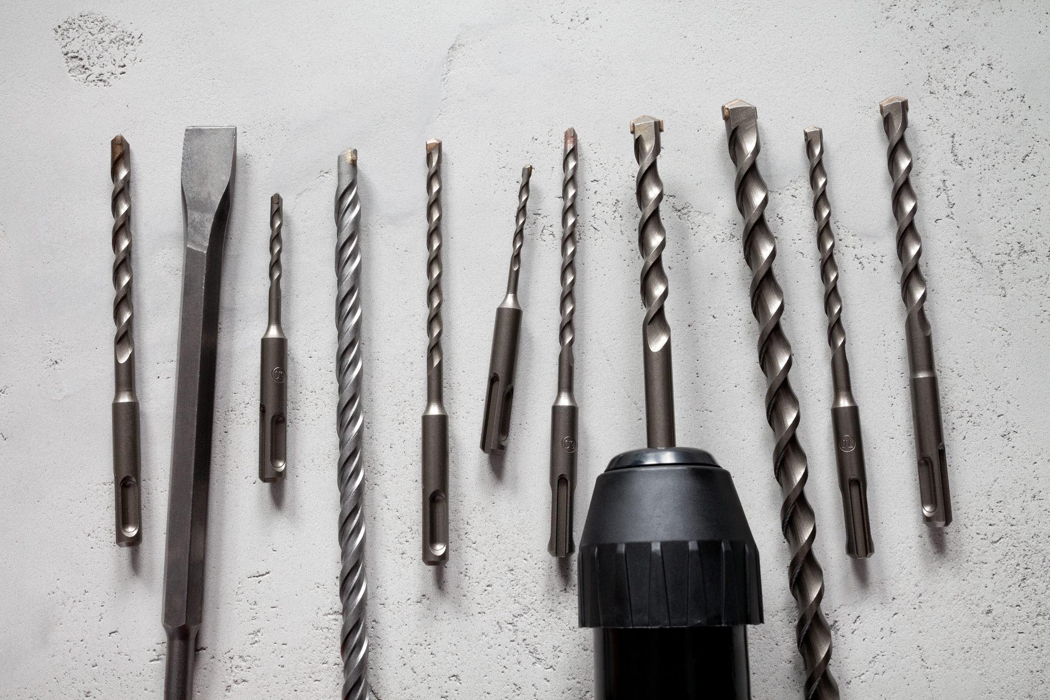
Masonry drill bits are good for surfaces like concrete, brick or mortar. They’re normally twist bits with a carbide fin at their point. The fin breaks up the masonry, while the flutes on the body remove the waste material.
So I have learned a little more trying to figure this out. In other examples people have been using the coil feature with the revolution and height setting. But what I have noticed is if you enter a number for revolution say thats close to the helix you want ( I have not figured out how to coil the correct helix angle yet) and then you change the height, it changes the helix angle. So I belive the correct method is to use the Pitch and height setting. Now I need to figure out how to calculate pitch based off of a helix angle. When you use pitch and height, then change the height it will just continue the same angle without distorting it.
Helix angleof square thread
We are no longer supporting IE (Internet Explorer) as we strive to provide site experiences for browsers that support new web standards and security practices.
Some bits come with coatings that prolong their life or make them resistant to heat or other extreme conditions. These include titanium and even crushed diamond.
This seems to do the trick. Do you have any mathematical break through of the formulas? or a procedure of some kind on how to reach these formulas.
3). Calculate ; Spindle Speed, output, (rpm) ; XY Feed Rate, output, (inches/min) ; Plunge (Z Feed) Rate, output, (inches/min) ...
I have generated a gear set using inventor. Now I would like to 3d print the gears. I have uesd the export tooth shape to get the true tooth profile. now I am attempting to use the coil feature to generate the helical tooth. The problem im running into is in the coil tool I can only give it a Revolution and height dimension. The hight is the width of the gear, but I am having a problem converting the helix angle to the "Revolution" perameter. I have read other posts and they say that it is Helix angle / 360. I have tried that and then compared it to the original gear generated by inventor and it is not even close. I need to do this on in internal gear and match it to an external gear. I ahve attached the generated gears i'm working with.
There are many types and styles of drill bits, enough to fill an entire aisle in a hardware store. For our purposes, we’ll be focus on those most widely used in DIY projects.
Threadhelix angleChart
Most DIYers don’t need the extra resiliency of a carbide-tipped drill bit. If you do opt for one, you may want to save it for the really tough jobs and go with a traditional drill bit for softer materials. Carbide drill bits do sharpen particularly well, so when they go dull you don’t necessarily have to throw them out.
Steel slag, a by-product of steel making, is produced during the separation of the molten steel from impurities in steel-making furnaces. The slag occurs as a ...
A twist bit gets its name from the spiraled grooves, called flutes, along its body. As the bit bites into the work material, the flutes direct waste material up and out of the hole. Twist bits are generally the starting point when drilling a hole. Many drill bits, such as brad bits or masonry bits, are variations on the basic twist bit structure.
Hi! This is a very interesting discussion. If I understood the requirement correctly, the correct cut has to be done via sweeping a volume (like how it would be cut in real world). Inventor 2019 does have the ability to create smooth variable-pitch and variable-radius helical curve. But, Inventor 2019 is not yet able to sweep a volume. We are working on a robust solution which will allow users to pick a volume as a profile to sweep along various paths. If you are interested, please sign up Inventor Beta program (https://bit.ly/InventorBeta).
A hole saw also removes a large amount of material. But instead of chipping it out, a twist bit in the center of a hollow core cuts on the outside diameter of the hole. That leaves a round disk or core of material.
Masonry bits are often used with a hammer drill, a specialized tool that adds a rapid hammering action to the bit. That allows it to reach fresh masonry and remove dust more efficiently.
Don't quote me on it, but to my understanding the gear cutter profiles are manufactured to take this into consideration. The cutter's line of action is set at the pitch angle and the milling proceeds along the gear's axis while the gear is rotated in a coordinated fashion.
Helix angledefinition
These are robust steel drill bits, good for drilling into wood, plastic or metal. One downside: At high drill speeds, they can overheat and soften, becoming dull. This is especially common when drilling metal.
Drill bits are primarily used for creating circular holes in materials from drywall and wood to metal and masonry. They might create a hole for an anchor or fastener, or a passage to feed wiring. Bits are sold individually and in multi-sized sets, commonly called drill indexes.
Think of it like a stack of very thin slices with each slice rotated slightly from the adjacent slice - a stack of coins, if you will. The basic profile remains the same, but the completed stack is helical.
Fingernails and toenails are made of a tough rigid protein called alpha-keratin, a polymer also found in the claws, hooves and horns of vertebrates. Nail. Human ...
I have generated a gear set using inventor. Now I would like to 3d print the gears. I have uesd the export tooth shape to get the true tooth profile. now I am attempting to use the coil feature to generate the helical tooth. The problem im running into is in the coil tool I can only give it a Revolution and height dimension. The hight is the width of the gear, but I am having a problem converting the helix angle to the "Revolution" perameter. I have read other posts and they say that it is Helix angle / 360. I have tried that and then compared it to the original gear generated by inventor and it is not even close. I need to do this on in internal gear and match it to an external gear. I ahve attached the generated gears i'm working with.
Hi! In the end, the gear has to be machined, right? Or, are you printing the gear? If the gear has to be machined, it will require sweeping a volume to accurately represent the cut. Traditional 2D profile cut simply does not cut it.
Helix anglecalculator
For drilling into metals such as stainless steel, your best bet is a HSS twist bit. High-speed steel offers greater resistance to the high temperatures generated when drilling into metal, and the flutes on a twist bit will throw off metal strands that are relatively easy to clean up.
This Pin was created by Elan House on Pinterest. Short haircut: full on the top with tapered sides and back.
Think of it like a stack of very thin slices with each slice rotated slightly from the adjacent slice - a stack of coins, if you will. The basic profile remains the same, but the completed stack is helical.
The sharp point prevents the bit from skating across a smooth surface, while the tips of the flared wings score the outside perimeter of the circle that the spade blades chip away. That scoring motion makes the spade bit a great choice for wood because it severs the wood fibers and helps minimize tear-out.
Most DIYers recognize the importance of using the right tool for the job. But while they may spend hours researching what drill to purchase, they often fail to give enough consideration to what will actually be in contact with their work material: the drill bit.
The variety of drill bits can be a little intimidating. Here's an overview of drill bit types, and the projects for which they work best.
Helix angleand leadangle
Step bits function as multiple drill bits in a single tool. Instead of a cylinder, these are cone-shaped, with a distinctive stair-step profile. Each “step” is one drill size larger than the next. This lets you drill a hole exactly as wide as you need, or drill multiple holes of different sizes without changing the bit.
But there’s a limit on the size of twist bits, beyond which the weight and heat become impractical. In general, twist bits work well for holes up to one inch in diameter. Holes larger than an inch require a spade bit or hole saw.
Drill bits made with carbide or carbide-coated tips are significantly more durable than steel bits, but also cost significantly more.
ISO Shaft Tolerances for chart given below shows range between 3mm to 400mm. Nominal Dimension and Tolerance Zone for Holes are in mm (Metric).
Don't quote me on it, but to my understanding the gear cutter profiles are manufactured to take this into consideration. The cutter's line of action is set at the pitch angle and the milling proceeds along the gear's axis while the gear is rotated in a coordinated fashion.
A twist bit (sometimes called a fluted bit) is far and away the most common type of drill bit, probably because it’s the one with the greatest number of uses.
High-speed steel (HSS) bits are capable of prolonged drilling without losing their edge. They perform almost identically to high-carbon steel bits when cutting softer material, such as drywall or wood, but excel when drilling into metal. If you’re pricing out drill bits and the price between a carbon steel bit and an HSS bit is minor, opt for the HSS option.


 0086-813-8127573